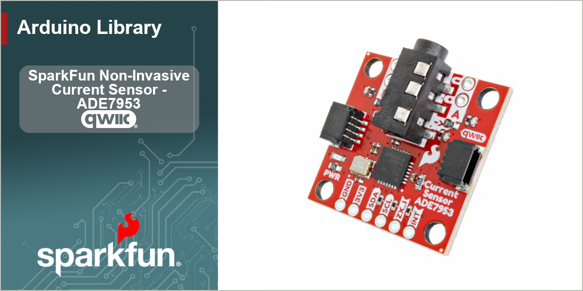
SparkFun Qwiic Current Sensor - ADE7953
Arduino Library for the SparkFun Qwiic Current Sensor (ADE7953)






The SparkFun Qwiic Current Sensor puts the Analog Devices ADE7953 single-phase energy metering IC on a Qwiic-enabled breakout, making clamp-on AC current measurement as simple as plugging in a cable. Paired with a current transformer (CT) clamp, the board measures RMS current without any electrical contact with the conductor being measured.
This library provides an easy-to-use interface to the ADE7953 over I2C, built on the SparkFun Toolkit. It handles the device setup for you and returns real-world current readings in amps, while still exposing the lower-level registers for advanced use.
Functionality
The library focuses on current measurement and the features most useful for it:
- RMS current measurement on Channel A (primary CT input) and the optional Channel B
- Real-world readings in amps, with built-in presets for common current clamps
- Programmable gain (PGA) and fine digital-gain control
- Software no-load calibration to remove the sensor's noise floor
- Peak / inrush current detection
- Zero-crossing detection and line-period (frequency) measurement
- A full interrupt system (overcurrent, zero-crossing, sag, cycle-end, and more)
- Sag detection and line-cycle accumulation configuration
- Diagnostics for the device's last-operation registers
[!NOTE] This library targets current measurement via CT clamp. The ADE7953 is a full energy-metering IC (active/reactive/apparent power and energy), and the register map for those features is present in the driver, but the convenience API is centered on current. The lower-level register helpers can be used to access the additional features.
Hardware Connections
The sensor connects over I2C using the Qwiic connector — no soldering required. The ADE7953 uses a single fixed 7-bit I2C address of 0x38.
| Pin / Header | Use | Notes |
|---|---|---|
| Qwiic / I2C | Power + communication | Standard 3.3V Qwiic connection |
| IAP / IAN | Current Channel A input | Connect your CT clamp here (primary channel) |
| IBP / IBN | Current Channel B input | Optional second CT clamp via the header pins |
| IRQ | Interrupt request (active low) | Optional — used for the interrupt examples |
| ZX | Zero-crossing output | Optional — pulses on each current zero crossing |
A burden resistor (5.6 Ω on the board) converts the CT's secondary current to a voltage the ADE7953 measures. The library's amps conversion accounts for this burden resistor and the CT turns ratio.
Using the Library
Installation
Install through the Arduino Library Manager by searching for SparkFun ADE7953, or download this repository as a ZIP and add it via Sketch > Include Library > Add .ZIP Library. This library depends on the SparkFun Toolkit, which the Library Manager will offer to install alongside it.
Getting Started
The I2C interface to the sensor is provided by the SfeADE7953ArdI2C class. Declare a sensor object:
In setup(), start I2C and call begin(). begin() confirms the device is present, applies the datasheet-recommended performance configuration, and sets sensible defaults (4x PGA gain and the high-pass filter enabled) so a basic sketch works with no further setup:
At this point the sensor is ready for normal operation.
Reading Current
The simplest way to read current is getCurrentA(), which returns the RMS current on Channel A in amps:
Channel B (the optional second input) is read with getCurrentB(). If you only need the raw register value, getIRMSA() / getIRMSB() return the unscaled RMS reading.
A Note on Return Values and Error Handling
Most library methods return a SparkFun Toolkit error code (ksfTkErrOk on success, a negative value on failure) and pass the value back through a reference parameter. This lets you tell the difference between a real reading of zero and a communication failure. For simple sketches you can ignore the return value:
For robust applications, check it:
Selecting a Current Clamp
To get accurate amps, the library needs the CT's turns ratio. Two common clamps are built in — pass one to setCurrentClamp() and it applies both the turns ratio and a suitable PGA gain for the board's 5.6 Ω burden resistor:
Using a different clamp? Enter the turns ratio directly:
Per-Channel Clamps
The methods above apply to both channels. To use a different clamp on each channel, use the A / B variants. For example, a 2000:1 clamp on Channel A and a direct (no transformer) measurement on Channel B:
setCurrentClampA() / setCurrentClampB() set the turns ratio and PGA gain for that channel only. setCurrentTransformerRatioA() / setCurrentTransformerRatioB() set just the ratio (leaving gain untouched) — pass 1.0 to measure that channel directly with no current transformer.
Calibration
Even with no current flowing, the ADC reports a small nonzero reading due to noise. autoCalibrateA() measures that no-load baseline by averaging a number of samples (taken with no current flowing) and removes it from future getCurrentA() readings:
The baseline is removed in the squared domain (sqrt(reading² − baseline²)), which is the correct way to subtract an RMS noise floor. Call clearCalibration() to reset it.
[!NOTE] The ADE7953 also has a hardware IRMS offset register (AIRMSOS), accessible via
setIRMSOffsetA()/getIRMSOffsetA(). That register operates in the squared domain with a scaling factor that depends on the datasheet, so the library'sautoCalibrateuses a software baseline instead, which is exact and portable.
Gain Configuration
The PGA gain is set per channel and is normally chosen for you by setCurrentClamp() or begin(). You can set it explicitly:
A digital (fine) gain can be applied on top of the PGA. Use a floating-point multiplier (1.0 = unity) and the library converts it to the nearest valid register value:
Peak / Inrush Detection
The ADE7953 continuously tracks the highest instantaneous current since the last reset — useful for catching motor startup surges and inrush:
Interrupts
Channel A and Channel B each have interrupt enable and status registers, exposed as a bitfield so you can set or test individual events by name:
Zero-Crossing and Line Frequency
Examples
The library ships with a set of examples that build from the basics to more advanced features:
- Example 01 - Basic Current Reading — the minimal sketch to read current in amps
- Example 02 - Dual Channel Current — read both channels and select a clamp
- Example 03 - Gain Configuration — PGA and digital gain
- Example 04 - Peak Detection — track peak / inrush current
- Example 05 - Zero Crossing — zero-crossing detection and line frequency
- Example 06 - Interrupt Pin — overcurrent interrupt on the IRQ pin
- Example 07 - Auto Calibration & Error Handling — no-load calibration and error checking
- Example 08 - Diagnostic Tool — an interactive serial diagnostic sketch
Documentation
API documentation is generated with Doxygen and published to GitHub Pages from the main branch.
Products That Use This Library
Contributing
If you would like to contribute to this library, please report issues and submit pull requests against the GitHub repository.
License Information
This product is open source!
This product is licensed using the MIT Open Source License
Please see LICENSE.md for more information.
- Your friends at SparkFun