Hardware Overview
Introduction
-
SparkFun GNSS Flex Breakout
SKU: GPS-28137

-
The SparkFun GNSS Flex Breakout board is a carrier board for our SparkPNT GNSS Flex modules. With pre-soldered headers, the GNSS Flex Breakout board provides access to all of the interfaces from a GNSS Flex module. We have also included two 6-pin JST connectors, same as the ones used on Pixhawk flight controllers. The JST connectors allow you to: connect the GNSS to a Pixhawk; or connect a radio to transfer RTCM correction data. Power can be provided by any or all of: the USB connectors or the
VINbreakout pin.The GNSS Flex Breakout comes populated with two sets of 2x10 pin, 2mm pitch male headers for attaching a GNSS Flex module. With these headers, the GNSS Flex system is designed to be modular so that boards are pin-compatible for upgrades and can be easily swapped for repairs. Depending on the capabilities of the GNSS Flex module that is connected, these pins will breakout the USB, UART (x4), I2C, and SD card interfaces for the GNSS receiver along with any PPS (x2) or event (x2) signals, using a standardized pin out. There board also has four LEDs indicators for power and the
PPS1,PVT, andRTKsignals from the GNSS Flex module.Note
By default, the CH342 USB-to-Serial converter chip is connected to both the GNSS
UART1andUART2interfaces. When you connect theUARTUSB port to your computer and install the driver, those two UART interfaces will appear as COM ports. If you need dedicated access to theUART1orUART2breakout pins, or want to use either of the JST connectors, you will need to disable the CH342. On this board, we have made this simple; just pull theCH342 ENbreakout pinLOWor connect it toGND. Otherwise, there is also aCH342 ENjumper you can solder instead.By default, Pin 1 of the JST connectors provides 5V output. But jumpers on the board allow the voltage to be changed to 3.3V. Or you can isolate the other power sources and connect an external 5V power input on Pin 1 instead. It is up to you.

Design Files
-
Design Files
-
Manipulate 3D Model
Controls Mouse Touchscreen Zoom Scroll Wheel 2-Finger Pinch Rotate Left-Click & Drag 1-Finger Drag Move/Translate Right-Click & Drag 2-Finger Drag 
Dimensions of the GNSS Flex Breakout board. Need more measurements?
For more information about the board's dimensions, users can download the KiCad files for this board. These files can be opened in KiCad and additional measurements can be made with the measuring tool.
KiCad - Free Download!
KiCad is free, open-source CAD program for electronics. Click on the button below to download their software. (*Users can find out more information about KiCad from their website.)
 Measuring Tool
This video demonstrates how to utilize the dimensions tool in KiCad, to include additional measurements:

Board Layout
The GNSS Flex system is designed around two 2x10-pin, 2mm pitch headers used mate the two types of boards. A standardized pin layout, keeps the ecosystem pin-compatible for upgrades and allows board to be easily swapped for repairs. Depending on the capabilities of the GNSS receiver, these pins will breakout the USB, UART (x4), I2C, and SD card interfaces along with any PPS or event signals of the GNSS receiver.

Layout of the major components of the GNSS Flex Breakout board.
The GNSS Flex Breakout has the following features:
-
- GNSS Flex Headers
- Two sets of 2x10 pin, 2mm pitch female headers for connecting a GNSS Flex module.
-
- Alignment Indicator
- Used to indicate the board alignment of a GNSS Flex module.
-
- Signal Bridges
- Two U.FL-to-SMA signal bridges, provide on-board adapters for connecting an external GNSS antenna(s) or another input/output signal(s).
-
- Status LEDs
- Four status indication LEDs for the attached GNSS Flex module.
-
- USB-C Connectors
- Used to access the USB and
UART1/UART2interfaces of a GNSS Flex Module.
-
- JST Connectors
- Breaks out the
UART1,UART2, and I2C, and interfaces of a GNSS Flex Module to connect a PixHawk controller or telemetry radio.
-
- SD Card Slot
- Depending on the capabilities of the GNSS Flex module, a µSD card slot is available for data logging.
-
- Qwiic Connector
- Depending on the capabilities of the GNSS Flex module, a Qwiic connector is available for connecting to a controller.
USB Connectors
Depending on the capabilities of the GNSS receiver, the USB connectors will break out the USB interface and/or UART interfaces from the GNSS Flex module.

The USB connectors on the GNSS Flex Breakout board.
USBUSB-C connector- If available, connects directly w/ GNSS Flex Module's USB interface
- 5V power input
-
UARTUSB-C connector- Interfaces to
UART1andUART2on the GNSS Flex Module via a CH342 USB-to-Serial converter - 5V power input
Info
To utilize the PTH pins or JST connections of the
UART1andUART2interfaces, the CH342 USB-to-Serial converter must be disabled with either theCH342 ENjumper or theCH342 ENPTH pin. - Interfaces to
SMA Connectors
The SMA connectors, provide users with a more robust connection for interfacing with signals to/from the GNSS Flex module. Each pair of U.FL and SMA connectors are bridged together and their ground plane isolated from the rest of the board, this allows users to pass signals between the GNSS Flex module and the GNSS Flex Breakout board. On the GNSS Flex Breakout board, we provide two sets of signal bridges. These signal bridges will primarily be used to attach an external GNSS antenna for their GNSS Flex module.

The RF signal bridges on the GNSS Flex Breakout, which provides a more robust SMA connection.
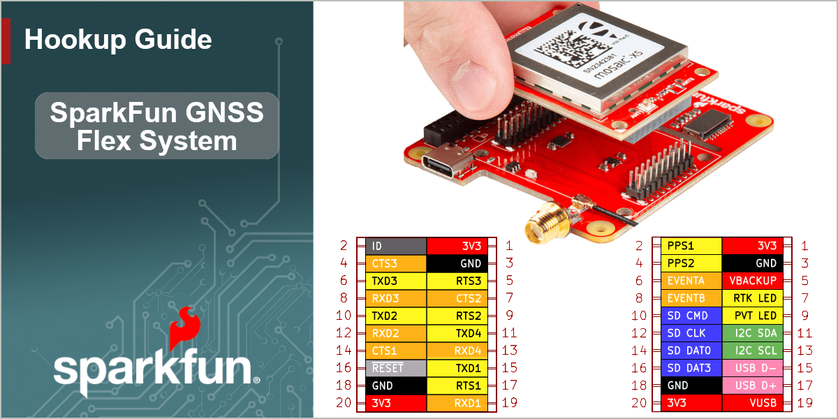
Breakout Pins
The primary function of the SparkFun GNSS Flex Breakout board is to expose the interfaces of the GNSS Flex modules. Most of which, are provided through the PTH pins.

The breakout pins on the board connected to the Flex header system.
Breakout Pins and Exposed Interfaces:
- Power Pins
- VIN
- 5V
- 3.3V
- 3.3V Enable
- Backup power
- Reset
- USB data
- UART (x4)
- SD card (see SD Card Slot)
- I2C bus
- PPS signals (x2)
- Status indicators (x2)
- Event triggers (x2)
- ID pin
Power
The simplest method to power the GNSS Flex breakout board is through the USB-C connectors. However, only 3.3V is required to power an attached GNSS Flex module; the 5V is only utilized for the USB interface and to power the JST connectors.

The GNSS Flex breakout board's power connections.
Below, is a general summary of the power circuitry on the board; most are broken out as PTH pins:
- Power Supplies - Power sources for the entire board
VIN- The general input voltage5V- The voltage from the USB-C connector, usually 5V.- Input Voltage Range: 2.2 - 5.5V (1)
- Powers the 3.3V voltage regulators
- They also power the JST connectors
3V3- Provides a regulated 3.3V from the AP7361C, using the power supplied from theVIN,5V, and/or USB-C connectors- Used to power the GNSSS Flex module, LEDs, and Qwiic connectors
- Controlled by the
3V3 ENpin, which is enabled by default
3V3 EN- Enables the voltage output from the AP7361C, 3.3V voltage regulator- Enabled by default (active
HIGH)
- Enabled by default (active
VBACKUP- Provides a regulated 3.3V from the RT9080, using the power supplied from theVIN,5V, and/or USB-C connectors- Provides backup power to the GNSS Flex module to maintain ephemeris data for warm starts
RESET- Used to reset the GNSS Flex moduleGND- The common ground or the 0V reference for the voltage supplies.
Backup Battery
When connecting an external battery or power source to the VBACKUP pin, users should disconnect the VBACKUP jumper.
JST Connector
The VOUT pins for the JST connectors are designed to operate as a voltage output. However, an input voltage can be supplied through the pin, but users should be mindful of any voltage contention issues.
Additionally, the jumper for the VOUT pin can be modified to change to output voltage level.
Info
For more details, users can reference the schematic and the datasheets of the individual components on the board.
Interfaces
The following interfaces and signals of the GNSS Flex system are connected to the 40-pin female GPIO header of the GNSS Flex Breakout board. Below, are tables detailing the pin connections for each interface.
If available, the USB interface of the GNSS Flex module can be accessed through the USB USB-C connector.

UART Numbering
Please note that the UART numbers (UART1 - UART4) listed below follows the GNSS Flex Module UART numbering scheme.

UART1- The
UART1interface can be accessed through either theUARTUSB-C connector,COM1 + I2CJST connector, orRX1/TX1/CTS1/RTS1set of PTH pins. However, in order to utilize theCOM1 + I2CJST connector orRX1/TX1/CTS1/RTS1PTH pins, the CH342 must be disabled using either theCH342 ENjumper or theCH342 ENPTH pin. UART2- The
UART2interface can be accessed through either theUARTUSB-C connector,COM2JST connector, orRX2/TX2/CTS2/RTS2set of PTH pins. However, in order to utilize theCOM2JST connector orRX2/TX2/CTS2/RTS2PTH pins, the CH342 must be disabled using either theCH342 ENjumper or theCH342 ENPTH pin. UART3- The
UART3interface can be accessed through theRX3/TX3/CTS3/RTS3set of PTH pins. UART4- The
UART4interface can be accessed through theRX4/TX4PTH pins.
The I2C interface can be accessed through either the Qwiic connector, COM1 + I2C JST connector, or SCL/SDA PTH pins. Depending on how the I2C bus is configured, users may need to use pull-up resistors, which can be enabled with the I^2^C jumper.

The two PPS signals can be accessed through the PPS1 and PPS2 PTH pins. The PPS1 pin is also connected to the PPS LED, which can be disabled with a jumper for low power applications.

The two event triggers can be accessed through the EVENTA and EVENTB PTH pins.

There are two status indicators, which can be accessed through the PVT and RTK PTH pins. These pins are also connected to the PVT and RTK LEDs, which can be disabled with their respective jumpers for low power applications.

The ID pin can be utilized to identify the GNSS receiver of a connected GNSS Flex module.

ID pin from the GNSS Flex system, used to identify a connected GNSS Flex module.
| GNSS Flex Module | ID Resistors | ID Value |
|---|---|---|
| mosaic-X5 | 1.0kΩ + 47.0kΩ | 0.06875V |
| LG290P | 3.3kΩ + 10.0kΩ | 0.81880V |
| DAN-F10 | 5.62kΩ + 6.8kΩ | 1.49324V |
| ZED-X20P | 15.0kΩ + 12.1kΩ | 1.82657V |
LEDs
There are four status LEDs on the GNSS Flex Breakout:

The status LED indicators on the GNSS Flex Breakout board.
PWR- Power (Red)- Turns on once power is supplied to the board
PPS- Pulse-Per-Second (Yellow)- Indicates when there is a pulse-per-second signal from the GNSS Flex module
RTK- RTK (White)- Usually indicates when an RTK fix has been established or when the correct RTCM data is being received by the GNSS Flex module
PVT- PVT (Blue)- Usually indicates when an GNSS lock or a position fix has been established by the GNSS Flex module
Info
For low power applications, the LEDs can be disabled to conserve energy. See the Jumpers section.
JST Connectors
There are two locking JST-GH connectors to easily access the UART and I2C interfaces of the GNSS Flex headers. Depending on the capabilities of the GNSS Flex module, the UART and I2C interfaces could be used to configure and communicate with the GNSS receiver.

The JST connectors on the GNSS Flex Breakout board.
COM1 + I2C- Breaks out the
UART1and I2C interfaces for a connection to a Pixhawk flight controller - 5V power output
- Breaks out the
COM2- Breaks out the
UART2interface (w/ flow control) for connection to a telemetry radio - 5V power output
- Breaks out the
Power Options
By default, the locking JST connectors provide a 5V power output. However, an optional 3.3V power output can be configured by modifying the jumpers underneath the connectors, on the opposite side of the board.
These connector can also function as an optional 5V power input, when all other power sources have been disconnected from the GNSS Flex Breakout board.
Pin Connections
Below, are tables of the pin connections of each JST connector:
COM1 + I2C
|
||||||
|---|---|---|---|---|---|---|
| Pin Number |
1 (Left Side) |
2 | 3 | 4 | 5 |
6 (Right) |
| Label | 5V |
TXD1 |
RXD1 |
SCL |
SDA |
GND |
| Function | Power: 5V | UART - Transmit | UART - Receive | I2C - Clock | I2C - Data | Ground |
COM2
|
||||||
|---|---|---|---|---|---|---|
| Pin Number |
1 (Left Side) |
2 | 3 | 4 | 5 |
6 (Right) |
| Label | 5V |
TXD2 |
RXD2 |
CTS2 |
RTS2 |
GND |
| Function | Power: 5V | Transmit | Receive | Clear-to-Send | Ready-to-Send | Ground |
SD Card Slot
Depending on the capabilities of the GNSS receiver, the µSD card slot can be used for data logging.

The SD card slot on the GNSS Flex Breakout board.
Qwiic Connector
The Qwiic connector is attached to the I2C interface of the GNSS Flex headers. Depending on the capabilities of the GNSS Flex module, the I2C interface could be used to configure and communicate with the GNSS receiver.

The Qwiic connector on the GNSS Flex Breakout board.
What is Qwiic?
![]()
![]()
The Qwiic connect system is a solderless, polarized connection system that allows users to seamlessly daisy chain I2C boards together. Play the video, to learn more about the Qwiic connect system or click on the banner above to learn more about Qwiic products.

Features of the Qwiic System


Qwiic cables (4-pin JST) plug easily from development boards to sensors, shields, accessory boards and more, making easy work of setting up a new prototype.


There's no need to worry about accidentally swapping the SDA and SCL wires on your breadboard. The Qwiic connector is polarized so you know you’ll have it wired correctly every time.
The part numbers for the PCB connector is SM04B-SRSS (Datasheet) and the mating connector on the cables is SHR04V-S-B; or an equivalent 1mm pitch, 4-pin JST connection.


It’s time to leverage the power of the I2C bus! Most Qwiic boards will have two or more connectors on them, allowing multiple devices to be connected.
Jumpers
There are twelve jumpers on the GNSS Flex Breakout:
Never modified a jumper before?
Check out our Jumper Pads and PCB Traces tutorial for a quick introduction!
-

How to Work with Jumper Pads and PCB Traces

Jumpers on the bottom of the GNSS Flex Breakout board.
The jumpers for the status LEDs, can be cut to disable the associated LED.
PWR- Power (Red)PPS- Pulse-Per-Second (Yellow)RTK- RTK (White)PVT- PVT (Blue)
SHLD- These jumpers can be cut to isolate the shielding of the associated USB-C connector from the ground plane of the board.
VOUT- These jumpers can be modified to configure the I/O voltage of the JST connectors between 3.3V or 5V.
I2C- This jumper, next to the Qwiic connector, can be bridged to attach 2.2kΩ pull-up resistors to the I2C bus.
VBACKUP- This jumper can be disconnected to allow for an external battery to be connected
VBACKUPPTH pin. CH342 EN- This jumper can be shorted, to disable the CH342 USB-to serial converter. This allows the UART interfaces to be accessed from the PTH or JST connections, instead of their USB connection.
MEAS- This jumper can be utilized to measure the current coming into the
5Vpower rail from either of the USB and/orVINpower sources.