Hardware Assembly
GNSS Flex Headers
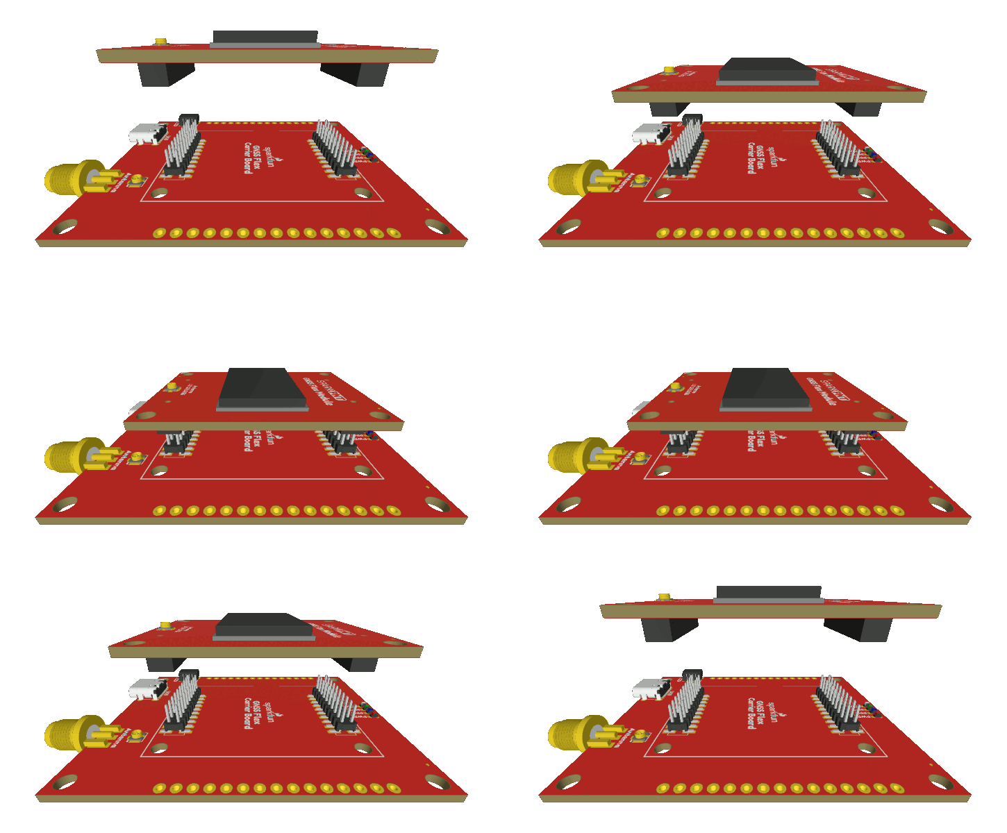
SparkPNT GNSS Flex modules are plug-in boards featuring different GNSS receivers. They are designed to be easily swapped for repairs and pin-compatible for upgrades. The boards come populated with two 2x10 pin, 2mm pitch female headers for connecting to carrier boards.
Stacking a GNSS Flex module onto a carrier board.
External GNSS Antenna
In order to receive GNSS signals, a compatible antenna is required. Users have the option of utilizing the integrated L1/L5 dual-band patch antenna or attaching an external GNSS antenna.
U.FL Connector
An external antenna can be connected to the U.FL connector on the GNSS Flex board with an U.FL to SMA adapter cable. For a sturdier connection, users also have the option to bridging the connection to the SMA connector on a Flex carrier board.
Attaching an U.FL cable to the GNSS Flex board.
Tip
For the best performance, we recommend users choose a compatible L1/L5 GNSS antenna and utilize a low-loss cable. Also, don't forget that GNSS signals are fairly weak and can't penetrate buildings or dense vegetation. The GNSS antenna should have an unobstructed view of the sky.
RF Switch
In order to trigger the RF switch inside the DAN-F10N GNSS module to utilize the U.FL connector as its signal source, the EXT_ANT jumper must be modified.
Soldering the EXT_ANT jumper on the DAN-F10N GNSS Flex module to utilize the GNSS antenna attached to the U.FL connector.
Never modified a jumper before?
Check out our Jumper Pads and PCB Traces tutorial for a quick introduction!


