Hardware Assembly
Danger
ESD Sensitivity
The mosaic-X5 GNSS receiver is sensitive to ESD. Use a proper grounding system to make sure that the working surface and the components are at the same electric potential.
ESD Precaution
As recommended by the manufacturer, we highly recommend that users take the necessary precautions to avoid damaging their module. For example, users can utilize the iFixit Anti-Static Wrist Strap.

Active Antenna
Never inject an external DC voltage into the SMA connector for the GNSS antenna, as it may damage the mosaic-X5 GNSS receiver. For instance, when using a splitter to distribute the antenna signal to several GNSS receivers, make sure that no more than one output of the splitter passes DC. Use DC-blocks otherwise.
Info
A 3 - 5.5V DC voltage can be applied to the main antenna from the VANT pin, obviating the need for an external antenna supply or bias-tee.
GNSS Antenna
In order to receive GNSS signals, users will need to connect a compatible antenna. For the best performance, we recommend users choose an active, L1/L2/L5/L6 GNSS antenna and utilize a low-loss cable.
U.FL Connector
GNSS antennas are connected to the U.FL connector on the GNSS Flex board. For sturdier connections, users have the option to bridging the connection to the SMA connector on a Flex carrier board.
Attaching an U.FL cable to the GNSS Flex board.
Tip
For the best performance, we recommend users choose a compatible L1/L2/L5/L6 GNSS antenna and utilize a low-loss cable. Also, don't forget that GNSS signals are fairly weak and can't penetrate buildings or dense vegetation. The GNSS antenna should have an unobstructed view of the sky.
GNSS Flex Headers
SparkPNT GNSS Flex modules are plug-in boards featuring different GNSS receivers. They are designed to be easily swapped for repairs and pin-compatible for upgrades. The boards come populated with two 2x10 pin, 2mm pitch female headers for connecting to carrier boards.
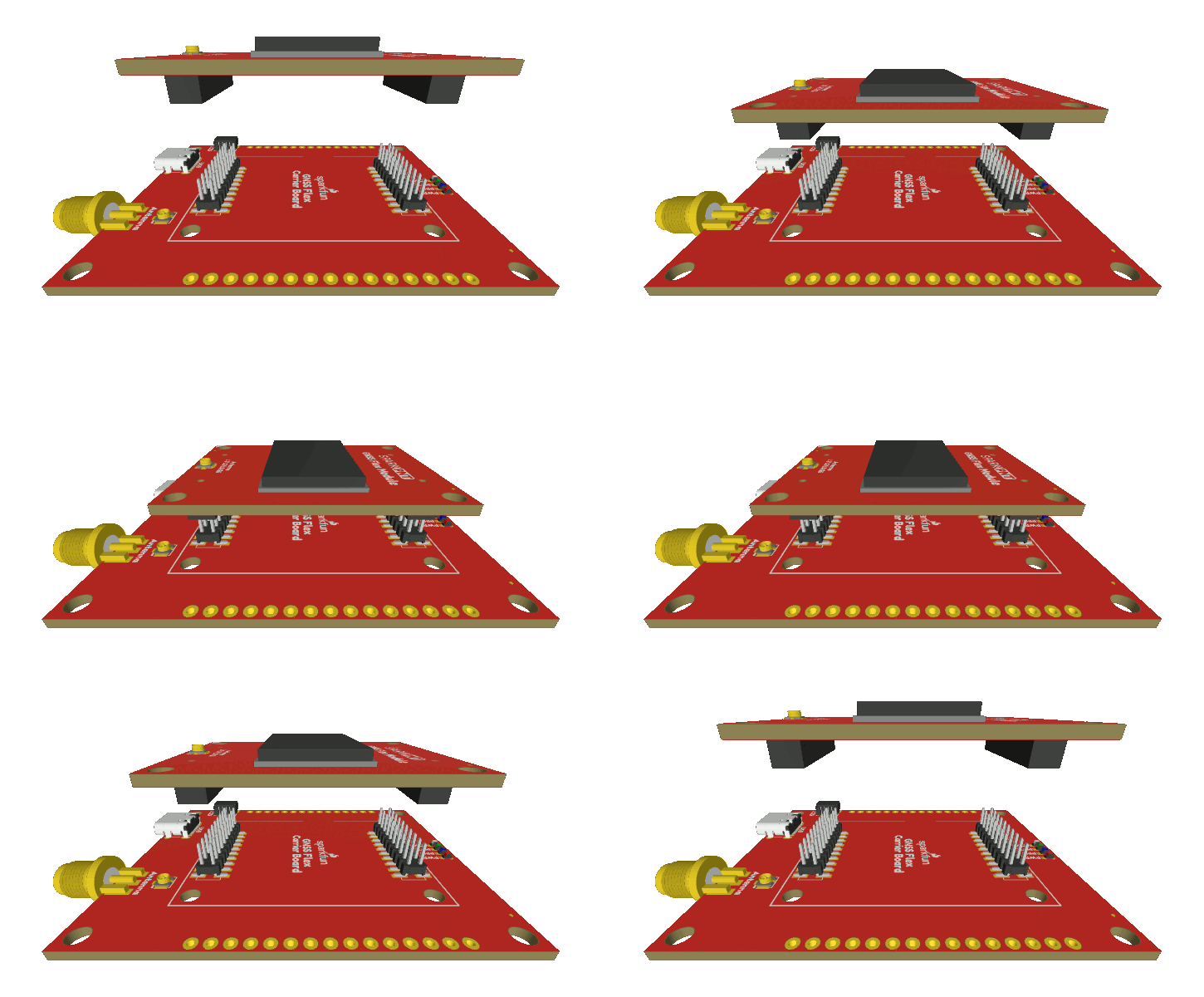
Stacking a GNSS Flex module onto a carrier board.

