Hardware Overview
Design Files
The SparkFun LG580P Quad-band GNSS RTK breakout board's dimensions, pin layout, and connectors are similar to our very popular SparkFun GPS-RTK-SMA Breakout - ZED-F9P (Qwiic) and SparkFun Quadband GNSS RTK Breakout - LG290P (Qwiic) boards, featuring a compact design and convenient Qwiic connectors.
Drop-in Replacement
Depending on your appication, this board could potentially function as a drop-in replacement. However, we advise users to verify the pin compatibility of this board with their current installation.
-
Design Files
- Schematic
- KiCad Files
- STEP File
- Board Dimensions:
- 1.70" x 1.80" (43.2mm x 45.7mm)
- Four mounting holes:
- 4-40 screw compatible
-
Manipulate 3D Model
Controls Mouse Touchscreen Zoom Scroll Wheel 2-Finger Pinch Rotate Left-Click & Drag 1-Finger Drag Move/Translate Right-Click & Drag 2-Finger Drag 
Dimensions of the LG580P GNSS breakout board. Need more measurements?
For more information about the board's dimensions, users can download the KiCad files for this board. These files can be opened in KiCad and additional measurements can be made with the measuring tool.
KiCad - Free Download!
KiCad is free, open-source CAD program for electronics. Click on the button below to download their software. (*Users can find out more information about KiCad from their website.)
 Measuring Tool
This video demonstrates how to utilize the dimensions tool in KiCad, to include additional measurements:

Board Layout
The SparkFun LG580P Quad-band GNSS RTK breakout board features the following:

Layout of the major components on the breakout board.
-
- USB-C Connector
- The primary inteface for powering and interacting with the board
-
- LG580P GNSS Module
- The Quectel LG580P GNSS module
-
- Header Pins
- Exposes pins to power the board and breaks out the interfaces of the LG580P GNSS module
-
- BlueSMiRF Header Pins
- Exposes the
UART2port of the LG580P GNSS module
-
- JST Connector
- Exposes the
UART3port of the LG580P GNSS module
-
- Qwiic Connectors
- Exposes the I2C interface of the LG580P GNSS module
-
- Status LEDs
- LED status indicators for the LG580P GNSS module
-
Antenna L1/2/5/6RF Connectors- SMA connectors for an external GNSS antennas
-
- Backup Battery
- Backup power to maintain ephemeris data on the LG580P GNSS module for warm starts
USB-C Connector
The USB connector is provided to power and communicate with the LG580P GNSS receiver. For most users, it will be the primary method for interfacing with the LG580P.

USB-C connector on the Quad-band GNSS RTK breakout board.
CH342 Converter
The CH342 serial-to-USB converter allows users to interface with the UART1 port of the LG580P GNSS module through the USB-C connector. Although the CH342 provides a dual-channel UART interface, only a single channel is utilized to communicate with the LG580P GNSS module. To utilize the CH342, users may need to install a USB driver, which can be downloaded from the manufacturer website.
Once the USB driver is installed:
- Two virtual
COMports will be emulated, which can be used as standardCOMports to access the receiver. - Users should select UART port with the enumeration labeled as
Channel A.
USB Drivers
Linux
A USB driver is not required for Linux based operating systems.
Power
The Quad-band GNSS RTK breakout board only requires 3.3V to power the board's primary components. The simplest method to power the board is through the USB-C connector. Alternatively, the board can also be powered through the other connectors and PTH pins.

Quad-band GNSS RTK breakout board's power connections.
Below, is a general summary of the power circuitry for the board:
5V- The voltage from the USB-C connector, usually 5V.- Can be utilized as the primary power source for the entire board.
3V3- 3.3V power rail, which powers the LG580P GNSS module, backup battery, and the power LED.- Power can also be distributed to/from any of the
3V3PTH pins or JST connectors (Qwiic orUART3).- For power that is supplied through these connections, the LG580P requires a supply voltage of 3.0–3.6V.
- A regulated 3.3V is supplied by the RT9080, when powered from the
5VPTH pin or USB connector- Input Voltage Range: 1.2 to 5.5V (1)
- The RT9080 LDO regulator can source up to 600mA.
- Power can also be distributed to/from any of the
3V3_EN- Controls the power output from the RT9080 voltage regulator.- By default, the pin is pulled-up to 5V and to enable the RT9080 output voltage.
RST- Used to reset the LG580P GNSS module- Connected to the
RESET_Npin of the LG580P module, a system pin with an internal pull-up resistor. - Driving the pin
LOWfor at least 100ms and releasing it, triggers a hard reset.
- Connected to the
GND- The common ground or the 0V reference for the voltage supplies.- Backup Battery - Provides backup power to the GNSS module to maintain ephemeris data
- While the RT9080 LDO regulator has an input voltage range of 1.2 - 5.5V, a minimum supply voltage of 3.5V is recommended for a 3.3V output.
JST Connector
The VCC pin of the JST connector is designed to operate as a voltage output. However, an input voltage can be supplied through the pin, but users should be mindful of any voltage contention issues.
Additionally, the VSEL jumper can be modified to change to output voltage level of the VCC pin.
BlueSMiRF Header
The 3V3 pin of the BlueSMiRF header is designed to operate as a voltage output. However, an input voltage can be supplied through the pin, but users should be mindful of any voltage contention issues.
Additionally, the BT-VCC jumper can be modified to change to output voltage level of the 3V3 pin.
Info
For more details, users can reference the schematic and the datasheets of the individual components on the board.
Power Modes
- Acquisition:
- Module searches for satellites and to determine visible satellites, coarse frequency, and the code phase of satellite signals
- Tracking:
- Once acquisition is completed, the module tracks satellites and demodulates the navigation data from specific satellites
- Backup Mode:
- Reduces power consumption. Only backup domain is active and keeps track of time.
Power Consumption
The power consumption of the LG580P GNSS module depends on the GNSS signals enabled and the positioning mode.
Current Consumption:
- Acquisition: 98mA (323.4mW)
- Tracking: 116mA (382.8mW)
- Backup Mode: 18μA (59.4μW)
Backup Battery
While charged, the backup battery allows the GNSS module to maintain valid ephemeris data (time and GNSS orbital trajectories) that was stored. Otherwise, the GNSS module must restart acquiring and tracking satellites.
Time to First Fix:
- Cold Start: 28s
- Warm Start: 28s
- Hot Start: 1.8s
LG580P GNSS
The centerpiece of the Quad-band GNSS RTK breakout board, is the LG580P GNSS module from Quectel. The LG580P is a low-power, multi-band, multi-constellation GNSS receiver capable of delivering centimeter-level precision at high update rates. The built-in professional-grade interference signal detection and elimination algorithms, effectively mitigate multiple narrow-band interference sources and significantly improve signal reception performance in complex electromagnetic environments. In addition, the RTK and heading algorithms ensure reliable positioning in challenging scenarios such as urban environments and deep tree cover. With its performance advantages of high-precision and power consumption, this board is an ideal choice for high-precision navigation applications, such as intelligent robots, UAVs, precision agriculture, mining, surveying, and autonomous navigation.

The LG580P module on the Quad-band GNSS RTK breakout board.

General Features
- Supply Voltage: 3.0–3.6V
- Tracking Channels: 1040
- Concurrent signal reception: 5 + QZSS
L1,L2,L5,E6frequency bands
- Sensitivity:
- Acquisition: -145dBm
- Tracking: -160dBm
- Reacquisition: -155dBm
- Antenna Power: External
- GNSS Constellations and SBAS Systems:
- USA: GPS + WASS
- Russia: GLONASS + SDCM
- EU: Galileo + EGNOS
- China: BDS + BDSDAS
- Japan: QZSS + MSAS
- India: NavIC + GAGAN
- Korea: KASS
- Africa: ASECNA
- Auz/NZ: SouthPAN
- Accuracy of 1PPS Signal: 5ns
- Update Rate:
- Default: 10Hz
- Max: 20Hz
- Time to First Fix (without AGNSS):
- Cold Start: 28s
- Warm Start: 28s
- Hot Start: 1.8s
- RTK Convergence Time: 5s
- Dynamic Performance:
- Maximum Altitude: 10000m
- Maximum Velocity: 490m/s
- Maximum Acceleration: 4g
- Interfaces
- Operating temperature: -40°C to +85°C
- Footprint: 21mm × 16mm × 2.7mm
- Weight: 1.4g
Frequency Bands
The LG580P modules are multi-band, multi-constellation GNSS receivers. Below, is a chart illustrating the frequency bands utilized by all the global navigation satellite systems; along with a list of the frequency bands and GNSS systems supported by the LG580P GNSS module.
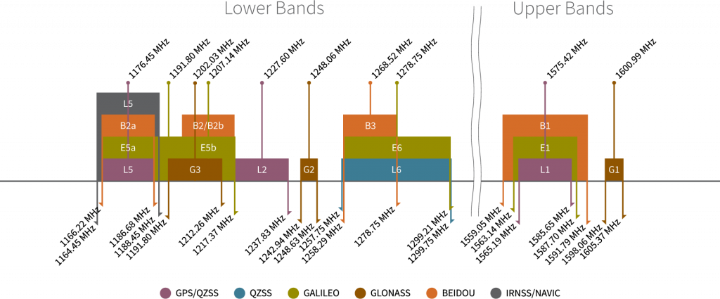
Frequency bands of the global navigation satellite systems. (Source: Tallysman)
Supported Frequency Bands:
- GPS:
L1 C/A,L5,L2C - GLONASS:
L1,L2 - Galileo:
E1,E5a,E5b,E6 - BDS:
B1I,B1C,B2a,B2b,B2I,B3I - QZSS:
L1 C/A,L5,L2C,L6 - NavIC:
L5 - SBAS:
L1 - L-band PPP2:
- PPP:
B2b - QZSS:
L6 - Galileo HAS:
E6
- PPP:
Supported GNSS Constellations:
- GPS (USA)
- GLONASS (Russia)
- Galileo (EU)
- BDS (China)
- QZSS (Japan)
- NavIC (India)
Supported SBAS Systems:
- WASS (USA)
- SDCM (Russia)
- EGNOS (EU)
- BDSBAS (China)
- MSAS (Japan)
- GAGAN (India)
- KASS (Korea)
- ASECNA (Africa)
- SouthPAN (Aus/NZ)
Info
For a comparison of the frequency bands supported by the LG580P GNSS modules, refer to sections 1.2, 1.5, and 1.6 of the hardware design manual.
What are Frequency Bands?
A frequency band is a section of the electromagnetic spectrum, usually denoted by the range of its upper and lower limits. In the radio spectrum, these frequency bands are usually regulated by region, often through a government entity. This regulation prevents the interference of RF communication; and often includes major penalties for any interference with critical infrastructure systems and emergency services.

However, if the various GNSS constellations share similar frequency bands, then how do they avoid interfering with one another? Without going too far into detail, the image above helps illustrate some of the characteristics, specific to the frequency bands of each system. With these characteristics in mind, along with other factors, the chart can help users to visualize how multiple GNSS constellations might co-exist with each other.
For more information, users may find these articles of interest:
GNSS Accuracy
The accuracy of the position reported from the LG580P GNSS module, can be improved based upon the correction method being employed. Currently, RTK corrections provide the highest level of accuracy; however, users should be aware of certain limitations of the system:
- RTK technique requires real-time correction data from a reference station or network of base stations.
- RTK corrections usually come from RTCM messages that are signal specific (i.e. an RTK network may only provide corrections for specific signals; only
E5band notE5a).
- RTK corrections usually come from RTCM messages that are signal specific (i.e. an RTK network may only provide corrections for specific signals; only
- The range of the base stations will vary based upon the method used to transmit the correction data.
- The reliability of RTK corrections are inherently reduced in multipath environments.
| Correction Method | Horizontal | Vertical | Heading | Velocity |
|---|---|---|---|---|
| Standalone | 1.0m ~3.3' |
1.5m ~4.9' |
3cm/s (0.108kph) ~1.2in/s (0.067mph) |
|
| RTK | 0.8cm (+1ppm) ~0.3" |
1.5cm (+1ppm) ~0.6" |
0.1° |
RTK Corrections
To understand how RTK works, users will need a more fundamental understanding of the signal error sources.
-

Real-Time Kinematics Explained
-

What is Correction Data?
Peripherals and I/O Pins
The LG580P GNSS features several peripheral interfaces and I/O pins. Some of these are broken out as pins on the Quad-band GNSS RTK breakout board; whereas, others are broken out to their specific interface (i.e. USB connector, JST connector, etc.). Additionally, some of their connections are tied to other components on the board.

The I/O pins on the Quad-band GNSS RTK breakout board.
The LG580P GNSS has three UART ports, which can be operated and configured separately.

Pin Connections
When connecting to the UART pins to another device, the signals should be connected based upon the flow of their data.
| Board | RX | TX | GND |
|---|---|---|---|
| UART Device | TX | RX | GND |
UART Settings
The UART ports have the following configuration settings:
- Logic Level: 3.3V
- Baudrate: 9600bps, 115200bps, 230400bps, 460800bps, 921600bps, and 3000000bps
- Data Bits: 8
- Parity: No
- Stop Bits: 1
- Flow Control: N/A
- Supported Protocols:
NMEA 0183(PQTM)RTCM 3.xQGC
Additional Support
All of the UART ports support firmware updates through their interface. In addition, the UART1 port also supports debugging data and the UART3 interface can be multiplexed for the CAN bus interface1.
UART1 can only be accessed from the USB-C connector, through the CH342 serial-to-USB converter. For Windows and MacOS computers, a USB driver must be installed in order to communicate with the LG580P module through the CH342 converter; however for Linux operating systems, the standard Linux CDC-ACM driver is suitable. Once the USB driver has been installed:
- Two virtual
COMports are emulated, which can be used as standardCOMports to access the receiver. - Users should select
COMport with the lower enumeration or listed asChannel A.
UART2 is available through the breakout PTH pins or the BlueSMiRF header pins. The pin layout of the BlueSMiRF header is pin compatible with many of our serial devices (i.e. UART adapters, serial data loggers, BlueSMiRF transceivers).
UART3 is available through the JST connector. The pin layout of the 4-pin locking JST-GH connector is compatible with many of our serial radios and adapter cables.
UART Protocols
UART Protocols
By default, these UART ports are configured to transmit and receive NMEA 0183, RTCM 3.x, and/or QGC messages. These messages are generally used for transmitting PNT data; providing or receiving RTK corrections; and receiving PPP data, respectively. Quectel also implements a system of proprietary messages (PQTM) for users to configure the LG580P that follows a data format similar to the NMEA protocol. The expected structure of these proprietary messages is shown below:

NMEA and PQTM protocols.

QGC protocol.
A full list of compatible NMEA 0183 v4.11 messages, is provided in section 2.2. Standard Messages of the GNSS Protocol Specification manual. This protocol is used for outputting GNSS data, as detailed by the National Marine Electronics Association organization.
List of Standard NMEA Messages
| Message | Type Mode | Message Description |
|---|---|---|
| RMC | Output | Recommended Minimum Specific GNSS Data |
| GGA | Output | Global Positioning System Fix Data |
| GSV | Output | GNSS Satellites in View |
| GSA | Output | GNSS DOP and Active Satellites |
| VTG | Output | Course Over Ground & Ground Speed |
| GLL | Output | Geographic Position – Latitude/Longitude |
| GBS | Output | GNSS Satellite Fault Detection |
| GNS | Output | GNSS Fix Data |
| GST | Output | GNSS Pseudorange Error Statistics |
| ZDA | Output | UTC Time & Date |
| HDT | Output | True Vessel Heading |
| THS | Output | True, Heading, and Status |
A full list of PQTM messages (proprietary NMEA messages defined by Quectel) supported by LG580P, is provided in section 2.3. PQTM Messages of the GNSS Protocol Specification manual. This protocol is used to configure or read the settings for the LG580P GNSS module.
List of Proprietary Quectel Messages
| Message | Type Mode | Message Description |
|---|---|---|
| PQTMVER | Output | Outputs the firmware version |
| PQTMCOLD | Command | Performs a cold start |
| PQTMWARM | Command | Performs a warm start |
| PQTMHOT | Command | Performs a hot start |
| PQTMSRR | Command | Performs a system reset and reboots the receiver |
| PQTMUNIQID | Command | Queries the module unique ID |
| PQTMSAVEPAR | Command | Saves the configurations into NVM |
| PQTMRESTOREPAR | Command | Restores the parameters configured by all commands to their default values |
| PQTMVERNO | Command | Queries the firmware version |
| PQTMCFGUART | Set/Get | Sets/gets the UART interface |
| PQTMCFGPPS | Set/Get | Sets/gets the PPS feature |
| PQTMCFGPROT | Set/Get | Sets/gets the input and output protocol for a specified port |
| PQTMCFGNMEADP | Set/Get | Sets/gets the decimal places of standard NMEA messages |
| PQTMEPE | Output | Outputs the estimated position error |
| PQTMCFGMSGRATE | Set/Get | Sets/gets the message output rate on the current interface |
| PQTMVEL | Output | Outputs the velocity information |
| PQTMCFGGEOFENCE | Set/Get | Sets/gets geofence feature |
| PQTMGEOFENCESTATUS | Output | Outputs the geofence status |
| PQTMGNSSSTART | Command | Starts GNSS engine |
| PQTMGNSSSTOP | Command | Stops GNSS engine |
| PQTMTXT | Output | Outputs short text messages |
| PQTMCFGSVIN | Set/Get | Sets/gets the Survey-in feature |
| PQTMSVINSTATUS | Output | Outputs the Survey-in status |
| PQTMPVT | Output | Outputs the PVT (GNSS only) result |
| PQTMCFGRCVRMODE | Set/Get | Sets/gets the receiver working mode |
| PQTMDEBUGON | Command | Enables debug log output |
| PQTMDEBUGOFF | Command | Disables debug log output |
| PQTMCFGFIXRATE | Set/Get | Sets/gets the fix interval |
| PQTMCFGRTK | Set/Get | Sets/gets the RTK mode |
| PQTMCFGCNST | Set/Get | Sets/gets the constellation configuration |
| PQTMDOP | Output | Outputs dilution of precision |
| PQTMPL | Output | Outputs protection level information |
| PQTMCFGODO | Set/Get | Sets/gets the odometer feature |
| PQTMRESETODO | Command | Resets the accumulated distance recorded by the odometer |
| PQTMODO | Output | Outputs the odometer information |
| PQTMCFGSIGNAL | Set/Get | Sets/gets GNSS signal mask |
| PQTMCFGSAT | Set/Get | Sets/gets GNSS satellite mask |
| PQTMCFGRSID | Set/Get | Sets/gets the reference station ID |
| PQTMCFGRTCM | Set/Get | Sets/gets RTCM |
| PQTMCFGSBAS | Set/Get | Configures SBAS |
| PQTMCFGNMEATID | Set/Get | Configures the NMEA Talker ID |
| PQTMTAR | Output | Outputs the time and attitude |
| PQTMCFGBLD | Set/Get | Configures the baseline distance |
| PQTMCFGRTKSRCTYPE | Set/Get | Configures RTK differential source type |
| PQTMSN | Command | Reads the SN of module |
| PQTMCFGANTINF | Set/Get | Configures the antenna information |
| PQTMCFGANTDELTA | Set/Get | Configures the delta between antennas |
| PQTMCFGSIGGRP | Set/Get | Configures the GNSS signal group |
| PQTMCFGSIGNAL2 | Set/Get | Configures GNSS signal mask for second antenna |
| PQTMCFGGEOSEP | Set/Get | Configures geoidal separation |
| PQTMCFGCNRTHD | Set/Get | Configures the CNR threshold for position engine |
| PQTMCFGELETHD | Set/Get | Configures the elevation threshold for position engine |
| PQTMNAV | Output | Outputs the navigation information |
| PQTMEOE | Output | Outputs the end of epoch information |
| PQTMCFGWN | Set/Get | Configures the reference start week number |
| PQTMANTENNASTATUS | Output | Reports the antenna status |
A full list of QGC messages (proprietary protocol defined by Quectel) supported by LG580P, is provided in section 3. QGC Protocol of the GNSS Protocol Specification manual. This protocol is used to output the PPP raw data.
List of Proprietary Quectel Messages
| GQC Message Name | Message Group | Message Number | Type | Description |
|---|---|---|---|---|
| RAW-PPPB2B | 0x0A | 0xB2 | Output | BDS PPPB2B binary raw messages |
| RAW-QZSSL6 | 0x0A | 0xB6 | Output | QZSSL6 binary raw messages |
| RAW-HASE6 | 0x0A | 0xE6 | Output | Galileo HASE6 binary raw messages |
A full list of compatible RTCM v3 messages, is provided in section 4. RTCM Protocol of the GNSS Protocol Specification manual. This protocol is used for transferring GNSS raw measurement data, as detailed by the Radio Technical Commission for Maritime Services organization.
List of Supported RTCMv3 (MSM) Messages
| Message | Type Mode | Message Description |
|---|---|---|
| 1005 | Input/Output | Stationary RTK Reference Station ARP |
| 1006 | Input/Output | Stationary RTK Reference Station ARP with height |
| 1019 | Input/Output | GPS Ephemerides |
| 1020 | Input/Output | GLONASS Ephemerides |
| 1041 | Input/Output | NavIC/IRNSS Ephemerides |
| 1042 | Input/Output | BDS Satellite Ephemeris Data |
| 1044 | Input/Output | QZSS Ephemerides |
| 1046 | Input/Output | Galileo I/NAV Satellite Ephemeris Data |
| 1073 | Input/Output | GPS MSM3 |
| 1074 | Input/Output | GPS MSM4 |
| 1075 | Input/Output | GPS MSM5 |
| 1076 | Input/Output | GPS MSM6 |
| 1077 | Input/Output | GPS MSM7 |
| 1083 | Input/Output | GLONASS MSM3 |
| 1084 | Input/Output | GLONASS MSM4 |
| 1085 | Input/Output | GLONASS MSM5 |
| 1086 | Input/Output | GLONASS MSM6 |
| 1087 | Input/Output | GLONASS MSM7 |
| 1093 | Input/Output | Galileo MSM3 |
| 1094 | Input/Output | Galileo MSM4 |
| 1095 | Input/Output | Galileo MSM5 |
| 1096 | Input/Output | Galileo MSM6 |
| 1097 | Input/Output | Galileo MSM7 |
| 1113 | Input/Output | QZSS MSM3 |
| 1114 | Input/Output | QZSS MSM4 |
| 1115 | Input/Output | QZSS MSM5 |
| 1116 | Input/Output | QZSS MSM6 |
| 1117 | Input/Output | QZSS MSM7 |
| 1123 | Input/Output | BDS MSM3 |
| 1124 | Input/Output | BDS MSM4 |
| 1125 | Input/Output | BDS MSM5 |
| 1126 | Input/Output | BDS MSM6 |
| 1127 | Input/Output | BDS MSM7 |
| 1133 | Input/Output | NavIC/IRNSS MSM3 |
| 1134 | Input/Output | NavIC/IRNSS MSM4 |
| 1135 | Input/Output | NavIC/IRNSS MSM5 |
| 1136 | Input/Output | NavIC/IRNSS MSM6 |
| 1137 | Input/Output | NavIC/IRNSS MSM7 |
While not implemented yet, the I2C interface is available through the breakout PTH pins or the Qwiic connectors.

I2C Settings
By default, the UART ports are configured with the following settings:
- Logic Level: 3.3V
- I2C Address: N/A
- Bitrate: up to 400kbps
- Protocols:
NMEAPQTMRTCM
- Built-in 2.2kΩ pull-up resistors
While not implemented yet, the SPI interface is available through the breakout PTH pins.

SPI Settings
By default, the UART ports are configured with the following settings:
- Logic Level: 3.3V
- Baudrate: 1Mbps – 3Mbps
- Protocols:
NMEAPQTM- Firmware updates
SRDY Pin
The SDRY pin functions as the interrupt output for the SPI interface. By default, the pin is LOW.
From the module, the PPS output signal is a 3.3V signal output that can be accessed from the PPS PTH pin. The signal is also connected to the PPS LED, which can be used as a visual indicator for its operation.

Jumpers
See the Jumpers section for more details.
- There is a jumper attached to the
PPSLED. For low power applications, the jumper can be cut to disable thePPSLED.
Use Case
- Users could use this signal in conjunction with the event pins to synchronize two modules with each other.
- Users could use this signal to create their own Stratum 0 source for the NTP on a primary time server.
The RTK PTH pin operates as the RTK_STAT status indicator for the RTK positioning. The pin is also connected to the RTK LED, which can be used as a visual indicator for its operation.

Info
The RTK_STAT pin is used to indicate RTK status. The pin is at high level during startup.
- If the pin output is high, it indicates the module has entered the RTK fixed mode.
- If the pin output is low, it indicates that the module exited the RTK fixed mode or is in Backup mode.
- If the pin outputs an alternating pin level, it indicates that the module received the correct RTCM data and did not enter the RTK fixed mode. The default frequency is 10Hz.
Jumpers
See the Jumpers section for more details.
- There is a jumper attached to the
RTKLED. For low power applications, the jumper can be cut to disable theRTKLED.
The EVENT pin provides event inputs with adjustable input frequentness and polarity.

EVENT pin on the Quad-band GNSS RTK breakout board.
Use Case
Users could use this pin in conjunction with the PPS signal to synchronize two modules with each other.
The RST pin can be used to reset the LG580P module if it enters an abnormal state. To reset the GNSS module, the pin must be low for more than 100ms.

RST pin on the Quad-band GNSS RTK breakout board.
SMA Connectors
There are two SMA connectors on the Quad-band GNSS RTK breakout board. The Antenna-1 connector is the primary input for a GNSS antenna for the LG580P GNSS receiver. The Antenna-2 connector operates as a secondary GNSS antenna input to provide a heading and pitch solution from the LG580P GNSS receiver.

The SMA connectors for an external GNSS antennas on the Quad-band GNSS RTK breakout board.
Antenna Specifications
- Passive antennas are not recommended for the LG580P GNSS module.
- To mitigate the impact of out-of-band signals, utilize an active antenna whose SAW filter is placed in front of the LNA in the internal framework.
- DO NOT select and antenna with the LNA placed in the front.
- There is no need to inject an external DC voltage into the SMA connector for the GNSS antenna. Power is already provided from the LG580P module for the LNA of an active antenna.
Tip
For the best performance, we recommend users choose compatible L1/L2/L5/L6/L-Band GNSS antennas and utilize a low-loss cables. Also, don't forget that GNSS signals are fairly weak and can't penetrate buildings or dense vegetation. The GNSS antennas should have an unobstructed view of the sky.
JST Connector
The Quad-band GNSS RTK breakout features a 4-pin JST GH connector, which is polarized and locking. Users can access pins of the UART3 port with our breadboard cable. Otherwise, the connector's pin layout is compatible with any of our serial radios and adapter cables.

The JST connector on the Quad-band GNSS RTK breakout board.
Pin Connections
Pin Connections
When connecting the Quad-band GNSS RTK breakout board to other products, users need to be aware of the pin connections between the devices.
| Pin Number |
1 (Left Side) |
2 | 3 | 4 |
|---|---|---|---|---|
| Label | VCC | TX3 | RX3 | GND |
| Function |
Voltage Output - Default: 3.3V - Selectable: 3.3V or 5V |
UART3 - Receive |
UART3 - Transmit |
Ground |
When connecting the Quad-band GNSS RTK breakout board to our radios, the pin connections should follow the table below. If the flow control is not enabled, the only the RX, TX, and GND pins are utilized.
| Board | RX | TX | GND |
|---|---|---|---|
| Radio | TX | RX | GND |
As documented in the LoRaSerial product manual, the pin connections between a host system (i.e. Quad-band GNSS RTK breakout board) and the LoRaSerial Kit radio is outlined in the image below.
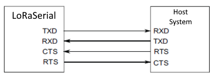
COM ports on the Quad-band GNSS RTK breakout board.
Jumpers
By default, the VSEL jumper is connected to 3V3 pad for a regulated 3.3V output on the 4-pin JST-GH connector.
BlueSMiRF Header
The Quad-band GNSS RTK breakout features a 6-pin BlueSMiRF PTH header for UART2. The pin layout of which, is compatible with many of our serial devices (i.e. UART adapters, serial data loggers, BlueSMiRF transceivers).

The 6-pin BlueSMiRF PTH header on the Quad-band GNSS RTK breakout board.
Jumpers
By default, the BT_VCC jumper provides a regulated 3.3V output to the BlueSMiRF header.
Status LEDs
There are four status LEDs on the Quad-band GNSS RTK breakout board:

The status LED indicators on the Quad-band GNSS RTK breakout board.
PWR- Power (Red)- Turns on once 3.3V power is supplied to the board
PPS- Pulse-Per-Second Signal (Yellow)- Indicates when there is a pulse-per-second signal (see the PPS Output section)
PVT- Position-Velocity-Time Solution (Blue)- On: Indicates the module has entered PVT mode
- Off: Indicates that the module has exited PVT mode or is in Backup mode.
RTK- Real-Time Kinematic Mode (White)- Indicates when an RTK fix has been established or when the correct RTCM data is being received (see the RTK section)
HEAD- Heading Solution (Green)- On: Indicates the module has entered Heading fixed mode
- Off: Indicates that the module has exited Heading fixed mode or is in Backup mode.
Jumpers
There are jumper attached to the LEDs. For low power applications, these jumpers can be cut to disable their respective LED. See the Jumpers section for more details.
Jumpers
Never modified a jumper before?
Check out our Jumper Pads and PCB Traces tutorial for a quick introduction!
-

How to Work with Jumper Pads and PCB Traces
There are seven jumpers on the back of the board that can be used to easily modify the hardware connections on the board. From which, there are three jumpers that control power to the status LEDs on the board. By default, all the jumpers are connected, to power the status LEDs. For low power applications, users can cut the jumpers to disconnect power from each of the LEDs.

The jumpers on the back of the Quad-band GNSS RTK breakout board.
VSEL- This jumper can be modified to configure/disconnect theVCCpin of the 4-pin locking JST connector to/from3V3or5Vpower.BT_VCC- This jumper can be cut to disconnect the3V3BlueSMiRF header pin from the 3.3V output of the RT9080 LDO regulator.PWR- This jumper can be cut to remove power from the red, power LED.PPS- This jumper can be cut to remove power from the yellowPPSLED, indicating when there is a PPS signal.PVT- This jumper can be cut to remove power from the bluePVTLED, indicating a PVT solution or operation in PVT mode.RTK- This jumper can be cut to remove power from the whiteRTKLED, indicating RTK fix or operation in RTK mode.HEADING- This jumper can be cut to remove power from the greenHEADLED, indicating a heading solution or operation in Heading fixed mode.SHLD- This jumper can be cut to disconnect the shielding of the USB-C connector from theGNDplane of the board
Info
- By default, the
VSELjumper is connected to3V3pad for a regulated 3.3V output on the 4-pin JST-GH connector. - By default, the
BT_VCCjumper provides a regulated 3.3V output to the BlueSMiRF header.
-
Feature Under Development
Currently, only the UART interface is supported by the module. Support for the I2C, SPI, and CAN interfaces are still under development.
-
Feature Under Development
Corrections for some of the PPP services have not been implemented.
-
Feature Under Development
The event trigger has not been implemented.