Hardware Overview
Design Files
-
Design Files
- Schematic
- KiCad Files
- STEP File
- Board Dimensions:
- 1.70" x 1.70" (43.2mm x 43.2mm)
-
Manipulate 3D Model
Controls Mouse Touchscreen Zoom Scroll Wheel 2-Finger Pinch Rotate Left-Click & Drag 1-Finger Drag Move/Translate Right-Click & Drag 2-Finger Drag 
Dimensions of the ZED-X20P GNSS breakout board. Need more measurements?
For more information about the board's dimensions, users can download the KiCad files for this board. These files can be opened in KiCad and additional measurements can be made with the measuring tool.
KiCad - Free Download!
KiCad is free, open-source CAD program for electronics. Click on the button below to download their software. (*Users can find out more information about KiCad from their website.)
 Measuring Tool
This video demonstrates how to utilize the dimensions tool in KiCad, to include additional measurements:

Board Layout
The SparkFun Allband GNSS RTK Breakout - ZED-X20P (Qwiic) features the following:

Layout of the major components on the breakout board.
-
- USB-C Connector
- The primary inteface for powering and interacting with the board
-
- ZED-X20P GNSS Module
- The u-blox ZED-X20P GNSS module
-
- Header Pins
- Exposes pins to power the board and breaks out the interfaces of the ZED-X20P GNSS module
-
- BlueSMiRF Header Pins
- Exposes the
UART2interface of the ZED-X20P GNSS module
-
- JST Connector
- Exposes the
UART2interface of the ZED-X20P GNSS module
-
- Qwiic Connectors
- Exposes the I2C interface of the ZED-X20P GNSS module
-
- Status LEDs
- LED status indicators for the ZED-X20P GNSS module
-
Antenna L1/2/5/6RF Connectors- SMA and U.FL (optional) connectors for an external GNSS antenna
USB-C Connector
A USB connector is provided to power the board and interface with the ZED-X20P GNSS receiver. For most users, it will be the primary method for communicating with the ZED-X20P module.

USB-C connector on the ZED-X20P GNSS breakout board.
Power
The simplest method to power the board is through the USB-C connector. However, the ZED-X20P GNSS breakout board only requires 3.3V to power most of its components(1), which can be supplied though JST connector, Qwiic connector, or PTH pins.
- 5V is only required to utilize the USB interface; and when enabled, it can also power the JST connector.

ZED-X20P GNSS breakout board's power connections.
Below, is a general summary of the power circuitry on the board; most are broken out as PTH pins:
VIN- The voltage from the USB-C connector, usually 5V.- Input Voltage Range: 1.2 - 5.5V (1)
- Power source for the entire board
- Powers the 3.3V voltage regulator (RT9080), which can source up to 600mA
- When enabled, it can also power the BlueSMiRF header
3V3- Provides a regulated 3.3V from the RT9080, using the power supplied from theVINpin or USB-C connector.- Used to power the ZED-X20P module, LEDs, Qwiic connectors, BlueSMiRF header, and backup battery
- Controlled by the
ENpin, which is enabled by default
EN- Enables the voltage output from the RT9080, 3.3V voltage regulator- Enabled by default (active
HIGH)
- Enabled by default (active
RST- Used to reset the ZED-X20P GNSS module- Connected to the
RESET_Npin of the ZED-X20P module, an input-only pin with an internal pull-up resistor (2) - Driving the pin
LOWfor at least 100ms triggers a cold-start reset, clearing theBBRcontent (receiver configuration, real-time clock (RTC), and GNSS orbit data)
- Connected to the
GND- The common ground or the 0V reference for the voltage supplies.- Backup Battery - Provides backup power to the ZED-X20P GNSS module to maintain ephemeris data for warm starts
-
While the RT9080 LDO regulator has an input voltage range of 1.2 - 5.5V, a minimum supply voltage of 3.5V is recommended for a 3.3V output.
-
No capacitors should be placed between
RESET_Nto GND, otherwise it could trigger a reset on every startup.
JST Connector
The VSEL pin of the BlueSMiRF header is designed to operate as a voltage output. However, an input voltage can be supplied through the pin, but users should be mindful of any voltage contention issues.
Additionally, the jumper for the VSEL pin can be modified to change to output voltage level.
Info
For more details, users can reference the schematic and the datasheets of the individual components on the board.
Power Consumption
The power consumption of the ZED-X20P module depends on the GNSS signals enabled and if the module is acquiring or tacking those signals. The table below, lists the average current consumption with a supply voltage of 3.3V.
| GNSS Signals | Acquisition | Tracking |
|---|---|---|
| GPS+GAL+BDS | 68mA | 64mA |
| GPS | 55mA | 55mA |
Tip
During acquisition, the current consumption may reach up to 85mA; make sure the primary power source can sustain this.
Info
For more information, please refer to the ZED-X20P Datasheet.
ZED-X20P GNSS Receiver
The centerpiece of this GNSS breakout board is the ZED-X20P module from u-blox; it features their latest X20 GNSS engine, a successor to their popular F9 engine. The ZED-X20P module is an all-band, high precision GNSS receiver that concurrently processes signals from the GPS, Galileo, BeiDou, QZSS, and NavIC constellations across all GNSS frequency bands, including L-band. With positioning algorithms for Real-time Kinematics (RTK), PPP-RTK, and Precise Point Positioning* (PPP) technologies, the module supports standard RTCM corrections for Virtual Reference Stations (VRS) in a Network RTK setup or a local base station setup. Additionally, L-band correction services are natively supported without the need to integrate an external receiver, such as the NEO-D9S.
With its very high update rate, the ZED-X20P module is ideal for control applications, ensuring smooth and reliable operation. The module also protects system integrity with multi-layered defenses, including a Root of Trust, jamming and spoofing detection, cryptographic authentication of navigation messages through Galileo OSNMA, and more. The module also accommodates users with a diverse choice of interfaces including USB, UART, SPI, and I2C.
Note
*: Feature in development

The ZED-X20P module on the breakout board.

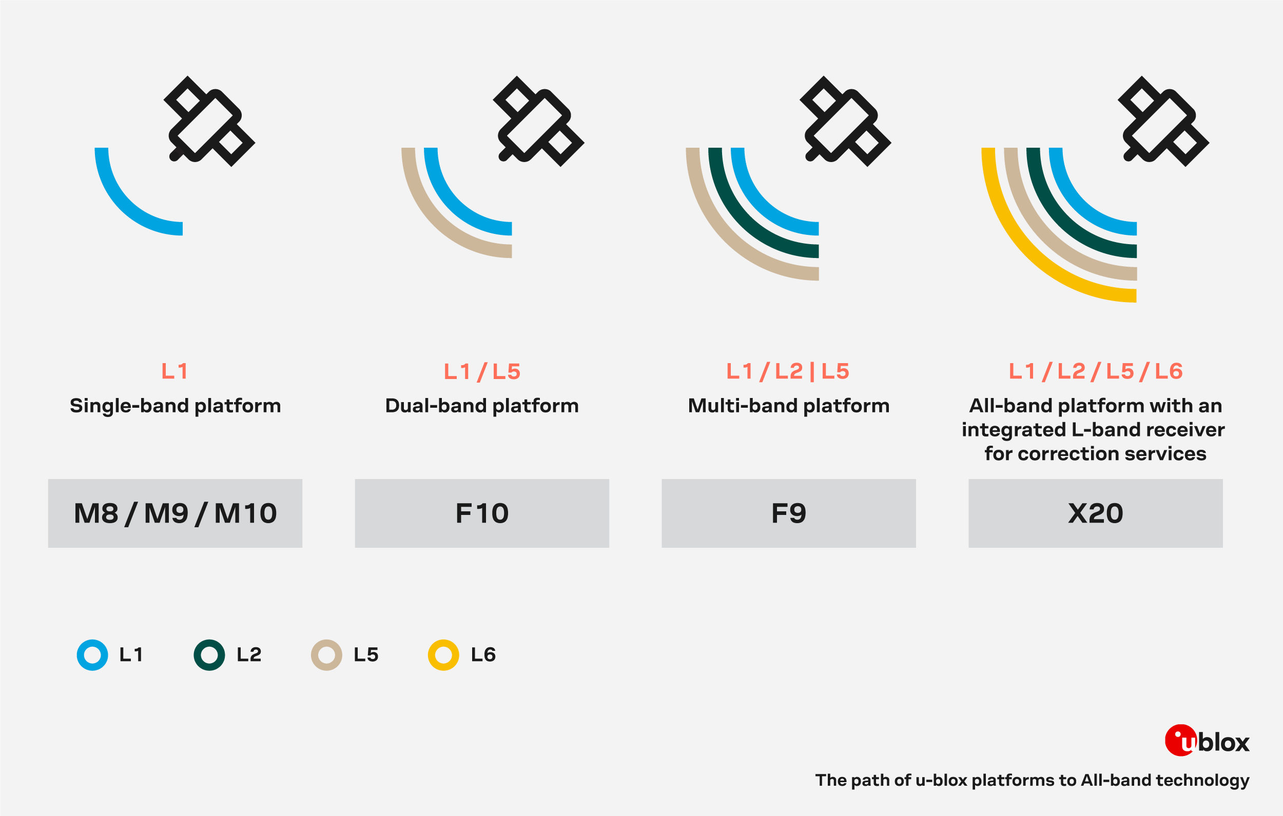
The frequency bands supported by the various u-blox GNSS engines.
Features:
- Supply voltage: 2.7V to 3.6V
- GNSS Constellations:
- GPS (USA)
- Galileo (EU)
- BDS (China)
- QZSS (Japan)
- NavIC (India)
- SBAS Systems:
- WASS (USA)
- EGNOS (EU)
- BDSBAS (China)
- MSAS (Japan)
- GAGAN (India)
- Sensitivity
- Tracking and Nav.: -167dBm
- Reacquisition: -160dBm
- Cold start: -148dBm
- Hot start: -158dBm
- Accuracy
- Dynamic
- Velocity: 0.03m/s
- Heading: 0.3°
- Time Pulse: 60ns
- Static/Position (GPS+GAL+BDS)
- Horizontal position accuracy (CEP)
- PVT: 1.2m
- SBAS: 0.6m
- RTK: 0.006m + 1ppm
- PPP-RTK: <0.06m
- PPP: <0.10m
- Horizontal position accuracy (CEP)
- Dynamic
- Operational limits
- Dynamics: <4g
- Altitude: 80,000m
- Velocity: 300m/s
- Update Rate: Up to 25Hz
- Time to Fix
- Cold Start: 25s
- Aided Start: 2s
- Hot Start: 2s
- Convergence time:
- RTK: <7s
- PPP-RTK: <40s
- PPP: <120s
- Features
- Programmable flash memory
- Carrier phase output
- Jamming detection
- Galileo OSNMA
- Secure boot
- Interfaces:
- USB
- UART x2
- SPI
- I2C
- Digital I/O
TIMEPULSEconfigurable: 0.25 - 10MHzEXTINTinput for Wakeup
- Protocols: NMEA 4.11, UBX binary, RTCM v. 3.4, SPARTN v. 2.0.2
- Services:
- AssistNow
- PointPerfect
- Operating temperature: -40°C to 85°C
- Dimensions: 17.0mm x 22.0mm x 2.4mm
Frequency Bands
The ZED-X20P module is an all-band, high precision GNSS receiver that concurrently processes signals from the GPS, Galileo, BeiDou, QZSS, and NavIC constellations across all GNSS frequency bands, including L-band. Below, are the frequency bands provided by all the global navigation satellite systems and the ones supported by the ZED-X20P module.
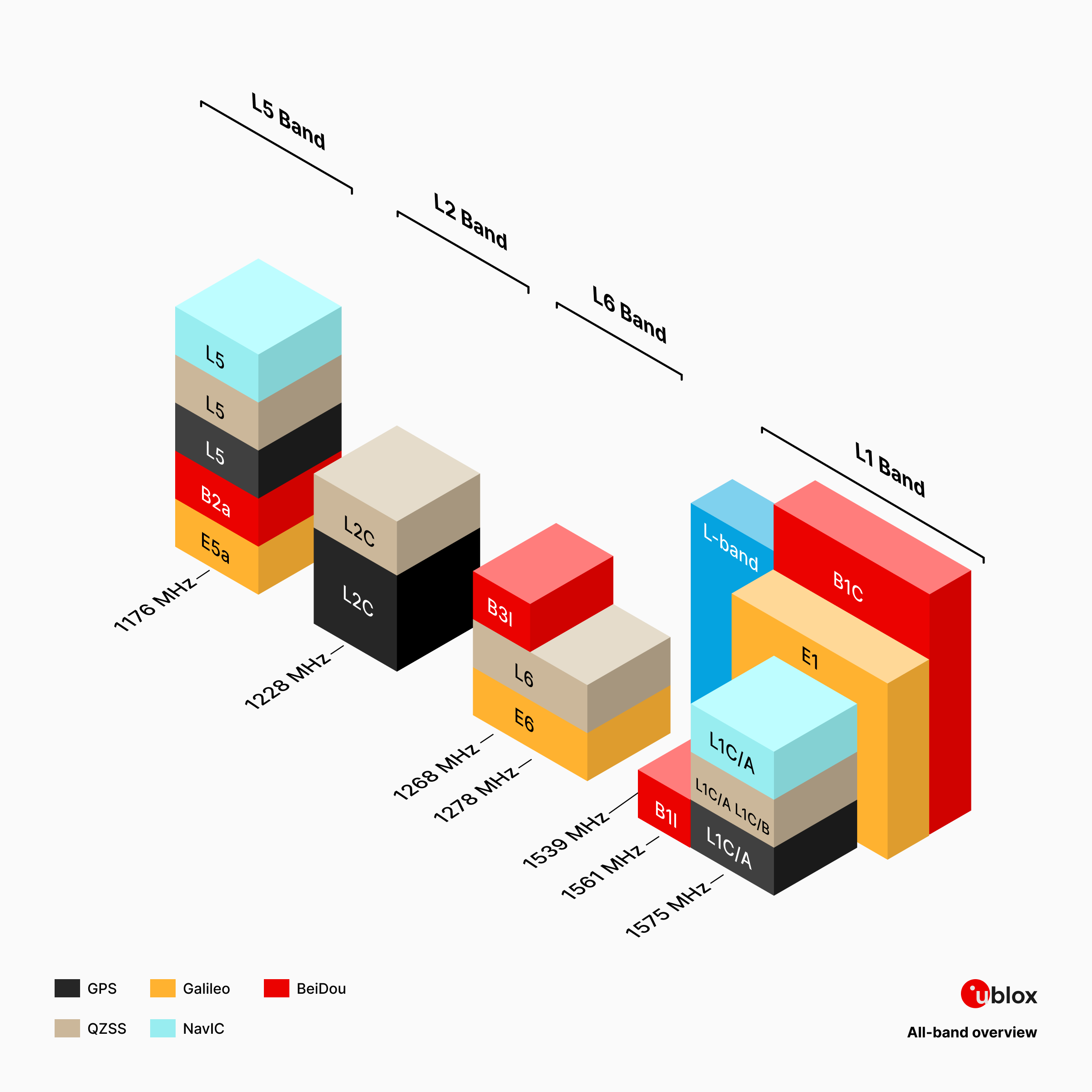
The frequency bands supported by the ZED-X20P GNSS receiver.
| Constellation | Frequency Bands |
|---|---|
| GPS | L1C/A, L2C, L5 |
| QZSS | L1C/A, L1C/B*, L2C, L5, L6 |
| GAL | E1B/C, E5a, E6 |
| BDS | B1I, B1C, B2a, B3I |
| NavIC | L1*, L5 |
| SBAS | L1C/A |
The supported frequency bands, organized by constellation.
Note
*: Feature in development
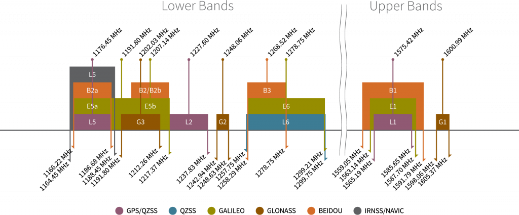
Frequency bands of the global navigation satellite systems. (Source: Tallysman)
Configuration Settings
Each GNSS constellations and their signal bands can be enabled or disabled independently, using keys from the CFG-SIGNAL-* configuration group; except for the QZSS and SBAS constellation. A GNSS constellation is considered to be enabled when the constellation enable key is set and at least one of the constellation's band keys is enabled. However, the ZED-X20P only supports certain combinations of constellations and bands. For all GNSS constellations, the L1 band is mandatory even in combination with another frequency band. Any unsupported combinations will be rejected with a UBX-ACK-NAK and the warning: inv sig cfg will be sent via UBX-INF and NMEA-TXT messages (if enabled).
Supported Combinations
Constellation keyCFG-SIGNAL-GAL_ENA |
Band keyCFG-SIGNAL-GAL_E1_ENA |
Band keyCFG-SIGNAL-GAL_E5A_ENA |
Band keyCFG-SIGNAL-GAL_E6_ENA |
Constellation enabled? |
|---|---|---|---|---|
true (1) |
true (1) |
true (1) |
true (1) |
yes |
true (1) |
true (1) |
true (1) |
false (0) |
yes |
true (1) |
true (1) |
false (0) |
true (1) |
yes |
true (1) |
true (1) |
false (0) |
false (0) |
yes |
true (1) |
false (0) |
true (1) |
true (1) |
no |
true (1) |
false (0) |
false (0) |
true (1) |
no |
true (1) |
false (0) |
true (1) |
false (0) |
no |
true (1) |
false (0) |
false (0) |
false (0) |
no |
false (0) |
true (1) |
true (1) |
true (1) |
no |
false (0) |
true (1) |
true (1) |
false (0) |
no |
false (0) |
true (1) |
false (0) |
true (1) |
no |
false (0) |
false (0) |
true (1) |
true (1) |
no |
false (0) |
false (0) |
false (0) |
true (1) |
no |
false (0) |
false (0) |
true (1) |
false (0) |
no |
false (0) |
true (1) |
false (0) |
false (0) |
no |
false (0) |
false (0) |
false (0) |
false (0) |
no |
What are Frequency Bands?
A frequency band is a section of the electromagnetic spectrum, usually denoted by the range of its upper and lower limits. In the radio spectrum, these frequency bands are usually regulated by region, often through a government entity. This regulation prevents the interference of RF communication; and often includes major penalties for any interference with critical infrastructure systems and emergency services.

However, if the various GNSS constellations share similar frequency bands, then how do they avoid interfering with one another? Without going too far into detail, the image above illustrates the frequency bands of each system with a few characteristics specific to their signals. Wit these characteristics in mind, along with other factors, the chart can help users to visualize how multiple GNSS constellations might co-exist with each other.
For more information, users may find these articles of interest:
Peripherals and I/O Pins
The ZED-X20P module has twenty-one I/O pins, of which eight are programmable. Most of these are broken out as PTH pins on the ZED-X20P GNSS breakout board; whereas, others are broken out to their specific interface (i.e. USB connector, jumper, U.FL connector, etc.). Additionally, some of the I/O connections are broken out with multiple components or interfaces.

The header pins on the ZED-X20P GNSS breakout board.
Interfaces:
- USB
- UART x2
- SPI
- I2C
- Address (7-bit): 0x42 (
1000010)
- Address (7-bit): 0x42 (
1x Antenna Detect(1)1x Antenna Short(2)1x Antenna Off(3)- 1x External interrupt
- 1x PPS output signal
- 1x TX Ready
- 1x RTK Stat
- 1x Geo Stat
- 1x D_Sel pin
- 1x Safe boot pin
- 1x Reset pin
- Not available on the ZED-X20P GNSS breakout board.
- Not available on the ZED-X20P GNSS breakout board.
- Not available on the ZED-X20P GNSS breakout board.
The ZED-X20P has two UART interfaces that can be accessed either through the PTH pins. The UART2 interface can also be accessed through the BlueSMiRF header and the JST connector.

Warning
Firmware updates can only be performed with the UART1 interface.
Tip
The UART RX interface will be disabled when more than 100 frame errors are detected during a one-second period. This can happen if the wrong baud rate is used or the UART RX pin is grounded. An error message appears when the UART RX interface is reenabled at the end of the one-second period.
Supported Protocols
The UART interface supports the following protocols:
- Input messages: NMEA (GGA, GLL, GSA, GSV, RMC, VTG, and TXT), RTCM, SPARTN, and UBX
- Output messages: NMEA, RTCM, and UBX
Configuration Settings
The UART interfaces can be configured with the CFG-UART* messages, but will initially have the following settings:
- Baudrate: 4800 to 8000000bps (Default: 38400bps)
- Data Bits: 8
- Parity: No
- Stop Bits: 1
- Flow Control: None
UART1Output- NMEA protocol with GGA, GLL, GSA, GSV, RMC, VTG, TXT messages are output by default.
- UBX and RTCM 3.4 protocols are enabled by default, but no output messages are enabled by default.
UART1Input- UBX, NMEA and RTCM 3.4 input protocols are enabled by default.
UART2Output- RTCM 3.4 protocol is enabled by default, but no output messages are enabled by default.
- NMEA protocol is disabled by default.
UART2Input- RTCM 3.4 and SPARTN protocols are enabled by default.
- NMEA protocol is disabled by default.
The ZED-X20P has a single I2C interface that can be accessed either through the PTH pins or the Qwiic connector.

Info
For users interested in the specific details about the read and write access for th I2C bus, please refer to the ZED-X20P integration manual
What is Qwiic?
![]()
![]()
The Qwiic connect system is a solderless, polarized connection system that allows users to seamlessly daisy chain I2C boards together. Play the video, to learn more about the Qwiic connect system or click on the banner above to learn more about Qwiic products.

Features of the Qwiic System


Qwiic cables (4-pin JST) plug easily from development boards to sensors, shields, accessory boards and more, making easy work of setting up a new prototype.


There's no need to worry about accidentally swapping the SDA and SCL wires on your breadboard. The Qwiic connector is polarized so you know you’ll have it wired correctly every time, right from the start.
The PCB connector is part number SM04B-SRSS (Datasheet) or equivalent. The mating connector used on cables is part number SHR04V-S-B or an equivalent (1mm pitch, 4-pin JST connector).


It’s time to leverage the power of the I2C bus! Most Qwiic boards will have two or more connectors on them, allowing multiple devices to be connected.

The ZED-X20P has a single SPI interface that can be accessed through the PTH pins. To enable the SPI interface, users must modify the SPI jumper.
| Labels | SPI Pins |
|---|---|
| TX1 | SDO |
| RX1 | SDI |
| SDA | CS |
| SCL | CLK |
The ZED-X20P module features five programmable I/O pins, but the LNA enable pin is not broken out on this board. All the inputs have internal pull-up resistors in normal operation and can be left open if unused.
LED Indicators
The PPS, RTK, and FENCE programmable I/O pins are also used as LED indicators.

Disable LEDs
There are jumper attached to the LEDs of the PPS, RTK, and FENCE pins. For low power applications, users can cut the jumper to disable the LED.
-
FENCE-
The
GEOFENCE_STATsignal indicates the current geofence status as to whether the receiver is inside any of the active areas. It is possible to configure up to four circular areas as geofence locations. Once configured, the receiver continuously compares its current position with the preset geofenced areas.The receiver toggles the assigned pin according to the combined geofence state.
- Inside - The position is inside the geofence with the configured confidence level
- Outside - The position lies outside of the geofence with the configured confidence level
- Unknown - There is no valid position solution or the position uncertainty does not allow for unambiguous state evaluation
Pin State
HIGH- TheGEOFENCE_STATpin is always set to high level when the combined geofence state is unknownLow- A low level can represent either an inside or outside state based upon theCFG-GEOFENCE-PINPOLconfiguration
-
RTK-
The
RTK_STATsignal indicates the RTK positioning status and if a stream of valid correction messages is being received.Pin State
LOW- Indicates that RTK fixed mode has been achieved- Blinking - Indicates that a valid stream of correction messages is being received and utilized, but no RTK fixed mode has been achieved
HIGH- Indicates that no carrier phase solution is available

EVENT pin on the ZED-X20P GNSS breakout board.
-
EVENT- ZED-X20P supports external interrupts through its
EXTINTpin. This is useful for waking the module up from its standby mode or for timing applications.

RST pin on the ZED-X20P GNSS breakout board.
-
RST-
The
RSTpin is connected to theRESET_Npin of the ZED-X20P module. Driving the pinLOWfor at least 100ms triggers a cold-start reset, clearing theBBRcontent (receiver configuration, real-time clock (RTC), and GNSS orbit data).Info
Capacitors should not be placed between
RSTandGND; otherwise, it could trigger a reset on startup.
-
D_SEL-
The
D_SELpin can be used to configure the functionality of the combinedUART1, I2C, and SPI interfaces. It is available as theSPIjumper on the back of the board.Info
When pulled
LOW(by closing the jumper), theD_SELenables the SPI interface on theUART1and I2C pins.
Note
The SAFEBOOT_N test point is for updates and reconfiguration. The ZED-X20P module will enter safeboot mode, if this pin is pulled LOW at startup.
The SAFEBOOT_N and TIMEPULSE (PPS) pins are internally connected in the ZED-X20P module, by a 1 kΩ series resistor. Make sure these pins have no load that could pull them low at startup; otherwise, the receiver will enter its safeboot mode.
BlueSMiRF Header
The UART2 interface of the ZED-X20P can be accessed either through the BlueSMiRF header pins or the JST connector. The BlueSMiRF header can be used to connect the ZED-X20P GNSS module to external devices, such as a microcontroller or BlueSMiRF v2, Bluetooth® serial link.

The BlueSMiRF header pins on the ZED-X20P GNSS breakout board.
Supported Protocols
The UART interface supports the following protocols:
- Input messages: NMEA and UBX
- Output messages: NMEA (GGA, GLL, GSA, GSV, RMC, VTG, and TXT)
Configuration Settings
The UART interface can be configured with the CFG-UART2-* messages, but will initially have the following settings:
- Baudrate: 9600 to 8000000bps (Default: 38400bps)
- Data Bits: 8
- Parity: No
- Stop Bits: 1
- Flow Control: None
Bus Contention
To avoid bus contention issues between the BlueSMiRF header pins or the JST connector; make sure only one devices is connected to either of these connection options.
Pin Connections
When connecting the ZED-X20P GNSS breakout board to another device, users need to be aware of the pin connections and voltage ranges of the products. Below, is a table of the pin connections for the BlueSMiRF header pins on the ZED-X20P GNSS breakout board.
| Pin Number |
1 (Left Side) |
2 | 3 | 4 | 5 |
6 (Right) |
|---|---|---|---|---|---|---|
| Label | NC |
TXD |
RXD |
3V3 |
NC |
GND |
| Function | UART - Transmit | UART - Receive | Output Voltage: 3.3V | Ground |
JST Connector
The UART2 interface of the ZED-X20P can be accessed either through the BlueSMiRF header pins or the JST connector. The JST connector can be used to connect the ZED-X20P GNSS module to external devices, such as the SiK Telemetry Radio V3 for RTK corrections.

The JST connector on the ZED-X20P GNSS breakout board.
Supported Protocols
The UART interface supports the following protocols:
- Input messages: NMEA and UBX
- Output messages: NMEA (GGA, GLL, GSA, GSV, RMC, VTG, and TXT)
Configuration Settings
The UART interface can be configured with the CFG-UART2-* messages, but will initially have the following settings:
- Baudrate: 9600 to 8000000bps (Default: 38400bps)
- Data Bits: 8
- Parity: No
- Stop Bits: 1
- Flow Control: None
Bus Contention
To avoid bus contention issues between the BlueSMiRF header pins or the JST connector; make sure only one devices is connected to either of these connection options.
Pin Connections
When connecting the ZED-X20P GNSS breakout board to another device, users need to be aware of the pin connections and voltage ranges of the products. Below, is a table of the pin connections for the JST connector on the ZED-X20P GNSS breakout board.
| Pin Number |
1 (Left Side) |
2 | 3 |
4 (Right) |
|---|---|---|---|---|
| Label | 3V3 |
TXD |
RXD |
GND |
| Function | Output Voltage: 3.3V | UART - Transmit | UART - Receive | Ground |
External Antenna
The ZED-X20P GNSS breakout board has two options for connecting an external GNSS antenna; the U.FL and SMA connectors. By default, the SMA connector is the primary interface. In order to utilize the U.FL connector, the RF jumper must be modified to redirect the signal path from the SMA connector. Then, an external antenna can be connected to the U.FL connector on the board with an U.FL to SMA adapter cable.

The RF connections to attach an external GNSS antenna to the ZED-X20P GNSS breakout board.

The RF jumper that needs to be modified to utilize the U.FL connector.
Tip
For the best performance, we recommend users choose a compatible L1/L5 GNSS antenna and utilize a low-loss cable. Also, don't forget that GNSS signals are fairly weak and can't penetrate buildings or dense vegetation. The GNSS antenna should have an unobstructed view of the sky.
Status LEDs

The status indicator LEDs on the ZED-X20P GNSS breakout board.
There are two status LEDs on the ZED-X20P GNSS breakout board:
PWR- Power (Red)- Turns on once 3.3V power is supplied to the board
PPS- Pulse-Per-Second (Yellow)- Indicates when there is a time pulse signal (see the PPS Output section)
-
RTK- RTK correction indicator (White)LED Status
- On - Indicates that no carrier phase solution is available
- Blinking - Indicates that a valid stream of correction messages is being received and utilized, but no RTK fixed mode has been achieved
- Off - Indicates that RTK fixed mode has been achieved
-
FENCE- Geofence status indicator (Blue)LED Status
- On - The
GEOFENCE_STATpin is always set to high level when the combined geofence state is unknown - Off - A low level can represent either an inside or outside state based upon the
CFG-GEOFENCE-PINPOLconfiguration
- On - The
Info
For low power applications, the LEDs can be disabled to conserve energy. See the Jumpers section.
Jumpers
Never modified a jumper before?
Check out our Jumper Pads and PCB Traces tutorial for a quick introduction!
-

How to Work with Jumper Pads and PCB Traces
There are eight jumpers on the back of the board that can be used to easily modify the hardware connections on the board.

The jumpers on the bottom of the ZED-X20P GNSS breakout board.
- LED Jumpers
-
Four of the jumpers control power to the status LEDs on the board.
Info
By default, all the jumpers are connected, to power the status LEDs. For low power applications, users can cut the jumpers to disconnect power from each of the LEDs.
PWR- This jumper can be cut to remove power from the red, power LED.PPS- This jumper can be cut to remove power from the yellow,PPSLED that is provided by thePPSsignal.RTK- This jumper can be cut to remove power from the white, RTK correction LED.FENCE- This jumper can be cut to remove power from the blue, Geofence status LED.
I2C- This jumper can be be modified to connect pull-up resistors to the
SCLandSDAconnections of the I2C interface. SPI- This jumper is connected to the
D_SELpin and can be modified to enable the SPI interface on theRX,TX,SDA, andSCLpins. VSEL- This jumper can be modified to configure/disconnect the
VCCpin of the 4-pin locking JST connector to/from3V3or5Vpower. SHLD- This jumper can be cut to disconnect the shield of the USB-C connector from the board's ground plane.