Hardware Assembly
Important: Read Before Use!
ESD Sensitivity
The mosaic-G5 P3 GNSS receiver is sensitive to ESD. Use a proper grounding system to make sure that the working surface and the components are at the same electric potential.
Info
As recommended by the manufacturer, we highly recommend that users take the necessary precautions to avoid damaging their GNSS receiver.
- The All-band GNSS RTK breakout board features ESD protection on the USB-C connector and breakout's I/O:
- USB data lines
- I/O PTH pads
- JST connector and BlueSMiRF header pins
- The mosaic-G5 P3 GNSS receiver features internal ESD protection to the
ANT_1antenna input.
Active Antenna
Never inject an external DC voltage into the SMA connector for the GNSS antenna, as it may damage the mosaic-G5 P3 GNSS receiver. For instance, when using a splitter to distribute the antenna signal to several GNSS receivers, make sure that no more than one output of the splitter passes DC. Use DC-blocks otherwise.
USB Programming
The USB connection is utilized for programming and serial communication. Users only need to plug their All-band GNSS RTK breakout board into a computer using a USB-C cable.

The All-band GNSS RTK breakout board with a USB-C cable attached.
Info
Once connected to a computer, the mosaic-G5 P3 module emulates two virtual COM ports. These can be used as standard COM ports to communicate with the GNSS receiver.
GNSS Antenna
In order to receive GNSS signals, users will need to connect a compatible antenna. For the best performance, we recommend users choose an active, L1/L2/L5/L6 GNSS antenna and utilize a low-loss cable.

Attaching a GNSS antenna to the SMA connector on the All-band GNSS RTK breakout board.
Active Antenna
Never inject an external DC voltage into the SMA connector for the GNSS antenna, as it may damage the mosaic-G5 P3 GNSS receiver. For instance, when using a splitter to distribute the antenna signal to several GNSS receivers, make sure that no more than one output of the splitter passes DC. Use DC-blocks otherwise.
Tip
Don't forget that GNSS signals are fairly weak and can't penetrate buildings or dense vegetation. The GNSS antenna should have an unobstructed view of the sky.
JST Connector
The JST connector on the All-band GNSS RTK board, breaks out the COM2 UART port of the mosaic-G5 P3 GNSS receiver. In most circumstances, users will utilize the JST connector to interface with one of our radio transceivers for RTK correction data.

Connecting a cable to the JST connector of the All-band GNSS RTK breakout board.
Pin Connections
When connecting the All-band GNSS RTK breakout board to our radios, only the RX, TX, and GND connections are required as outlined in the table below. By default, flow control is disabled on the mosaic-G5 P3 GNSS receiver and the connections are not available through the JST connector.
| Board | RX | TX | GND |
|---|---|---|---|
| Radio | TX | RX | GND |
All-band GNSS RTK Breakout Board
When connecting the All-band GNSS RTK breakout board to other products, users need to be aware of the pin connections between the devices. and voltage ranges of the products. Below, is a table of the pin connections for the JST connector on the All-band GNSS RTK breakout board.

| Pin Number |
1 (Left Side) |
2 | 3 |
4 (Right Side) |
|---|---|---|---|---|
| Label | + |
T |
R |
- |
| Function |
Voltage Output - Default: 3.3V - Selectable: 3.3V or 5V |
UART2 - Transmit |
UART2 - Receive |
Ground |
VSEL Pin
By default, the power pin (i.e. + or Pin 1) of the JST connector is connected to 3.3V and configured as a power output. An input voltage can be supplied through the pin; however, users should be mindful of any voltage contention issues.
Jumper
By default, the VSEL jumper is connected to 3V3 pad for a regulated 3.3V output. However, users can modify the jumper to utilize the voltage supplied from either the USB or VIN inputs.
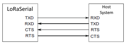
LoRa Radios
As documented in the LoRaSerial product manual, the pin connections between a host system (i.e. All-band GNSS RTK breakout board) and the LoRaSerial Kit radio is outlined in the image below.
Below, is a table of the pin connections for the JST connector on our radios.
| Pin Number |
1 (Left Side) |
2 | 3 | 4 | 5 |
6 (Right) |
|---|---|---|---|---|---|---|
| Label | 5V |
RX - SiK RXI - LoRaSerial |
TX - SiK TXO - LoRaSerial |
CTS | RTS | GND |
| Function |
Voltage Input - SiK: 5V - LoRaSerial: 3.3 to 5V |
UART - Receive | UART - Transmit |
Flow Control Clear-to-Send |
Flow Control Ready-to-Send |
Ground |
Breakout Pins
The PTH pins on the All-band GNSS RTK board are broken out into 0.1"-spaced pins on the outer edges of the board.
New to soldering?
If you have never soldered before or need a quick refresher, check out our How to Solder: Through-Hole Soldering guide.
-

How to Solder: Through-Hole Soldering


BlueSMiRF Header
To pair the All-band GNSS RTK breakout board with a mobile device, users will need to connect a BlueSMiRF v2 to the available header pins.

Soldering headers to the All-band GNSS RTK breakout board.

Connecting a BlueSMiRF v2 to female headers soldered on the All-band GNSS RTK breakout board.