Hardware Assembly
Recommended Setup
By default, the UART2 port is configured to receive the GNSS data required for the tilt-compensation. Whereas the default configuration of the UART1 and UART3 ports, the ports have the same functions. They can be connected to the main processor an/or used as a debugging, firmware upgrade, or configuration interface.
UART1- Connect to host device- Configuration, message output, and firmware upgrade
UART2- Connect GNSS boardUART3- Connect to host device- Configuration, message output, and firmware upgrade
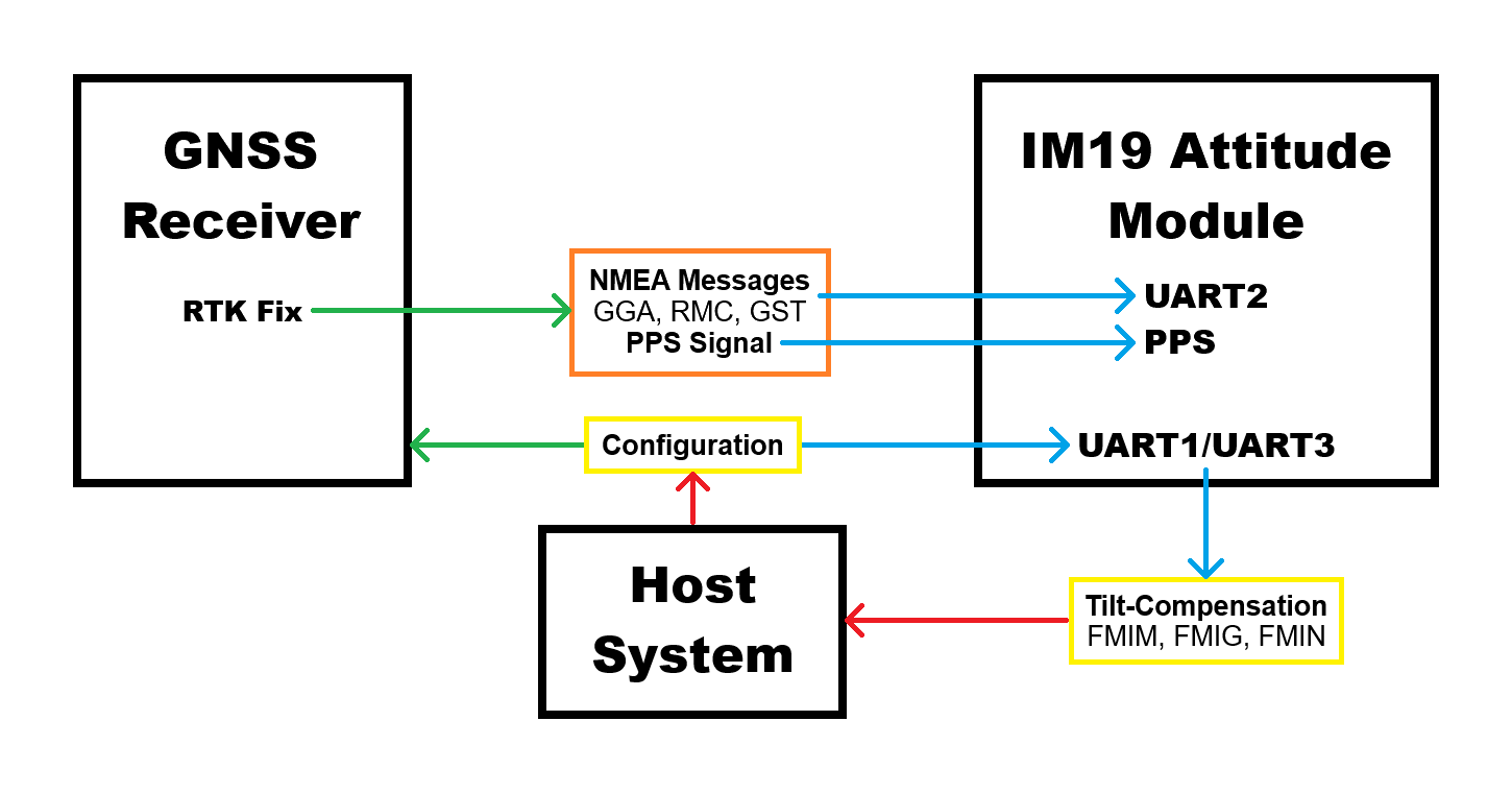
For the UART interface sending the GNSS messages to the IM19 breakout board, users will need to configure the UART port with the following settings:
- Baudrate: 115200bps
- Output NMEA Messages:
GPGGA,GPRMC, andGPGST - Solution Rate: 5Hz
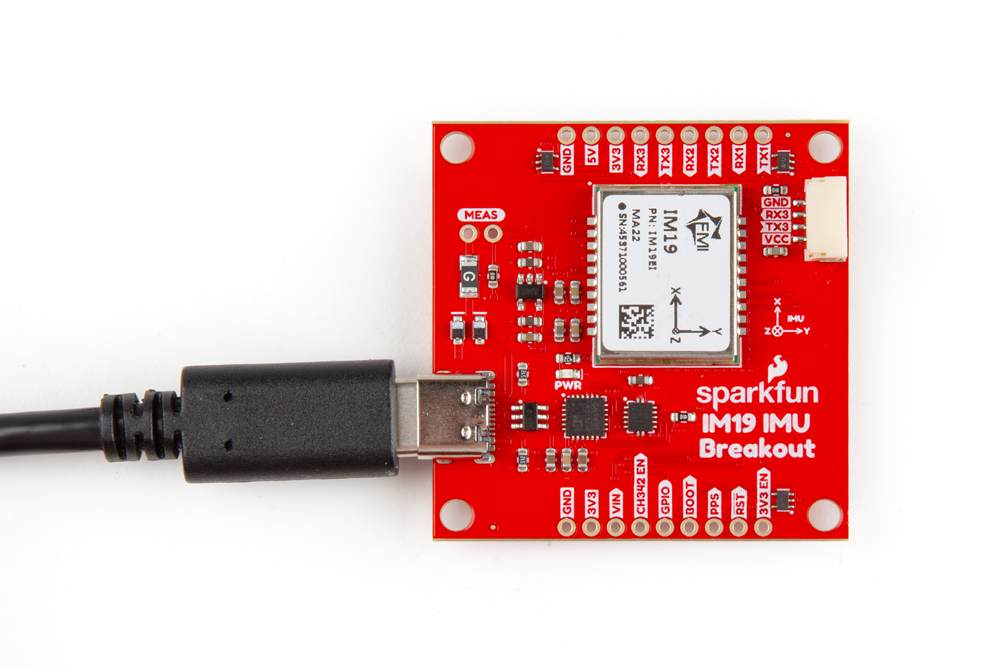
USB Connector
The USB connection can be utilized for serial communication and configuring the IM19 attitude module. Users only need to connect their IM19 breakout board to a computer, using a USB-C cable.
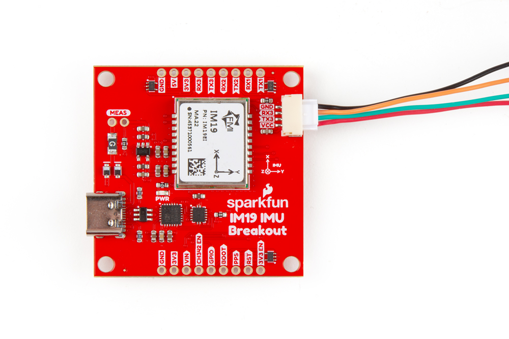
JST Connector
The JST connector on the IM19 board, breaks out the UART3 port of the IM19 attitude module. In certain circumstances, users want to utilize the JST connector to attach one of our radios or BlueSMiRF.
Radio Transceivers and Cables
- SiK Telemetry Radio V3 - 915MHz, 100mW
- SparkFun LoRaSerial Kit - 915MHz (Enclosed)
- BlueSMiRF - JST
- JST-GHR-04V to JST-GHR-06V Cable - 1.25mm pitch
- GHR-04V-S to GHR-06V-S Cable - 100mm
Users can modify the VCC jumper on the back of the board to enable a 5V output on the VCC pin.
When connecting the IM19 breakout board to other products, users should be aware of the pin connections between the devices. The table below, details the pin connections of the locking JST connector on the IM19 breakout board.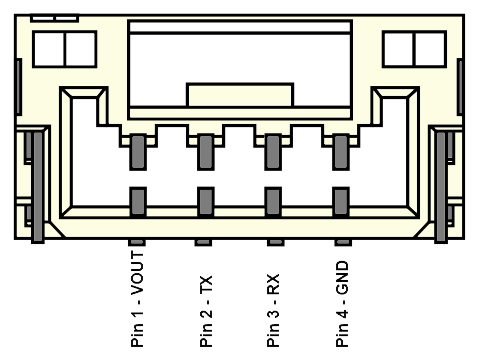
| Pin Number | 1 | 2 | 3 | 4 |
|---|---|---|---|---|
| Label | VCC | TX3 | RX3 | GND |
| Function | Voltage Output
| UART3 - Receive | UART3 - Transmit | Ground |
Users will need to configure the baud rate of the attach devices to match the UART port of the IM19 attitude module, which are set to 115200bps.
As documented in the LoRaSerial product manual, the baud rate for these radios are configured by the SERIAL_SPEED parameter. The default configuration is SERIAL_SPEED: 57600bps.
Breakout Pins
The PTH pins on the IM19 board are broken out into 0.1"-spaced pins on the outer edges of the board.
The board's pin layout is similar to some of our GNSS breakout boards and can be stacked using headers. However, users will need to configure the GNSS_PORT to the appropriate UART interface.
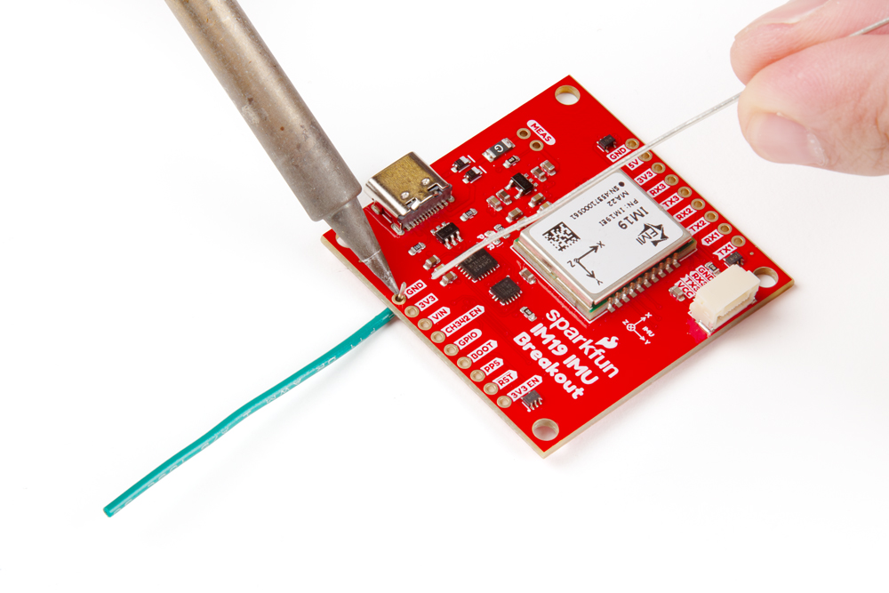
If you have never soldered before or need a quick refresher, check out our How to Solder: Through-Hole Soldering guide.
The breakout board also includes a digital switch, to isolate the CH342 and allow users to access the UART1 and UART2 ports of the IM19 attitude module through their breakout pins. To activate the digital switch and utilize the UART ports through their breakout pins, users can close the CH342 EN jumper or pull theCH342 EN pin LOW. This disables the CH342 and disconnects the CH342 from the UART1 and UART2 ports of the IM19 attitude module, avoiding any bus contention issues.
Headers
When selecting headers, be sure you are aware of the functionality you require.
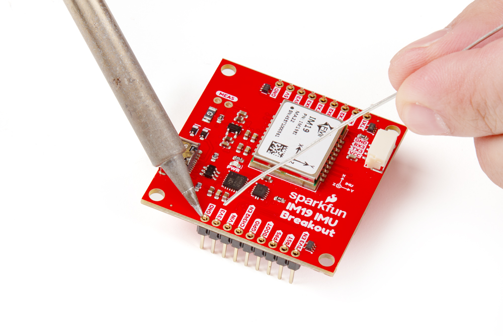
Hookup Wires
For a more permanent connection, users can solder wires directly to the board.