Hardware Overview
Board Layout
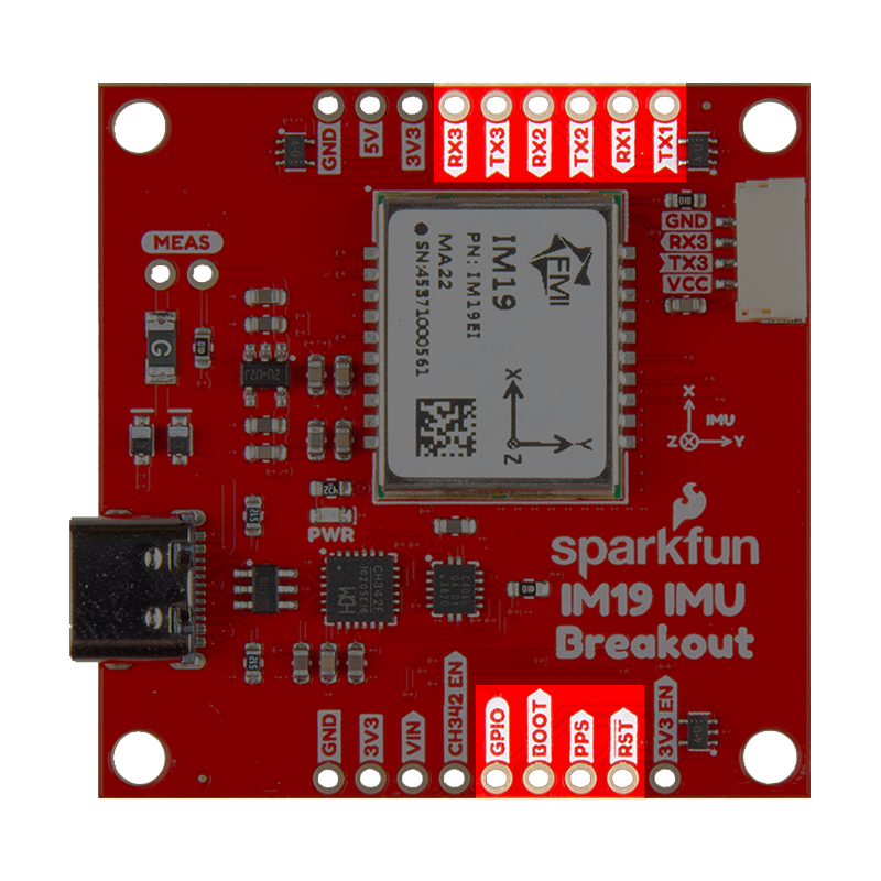
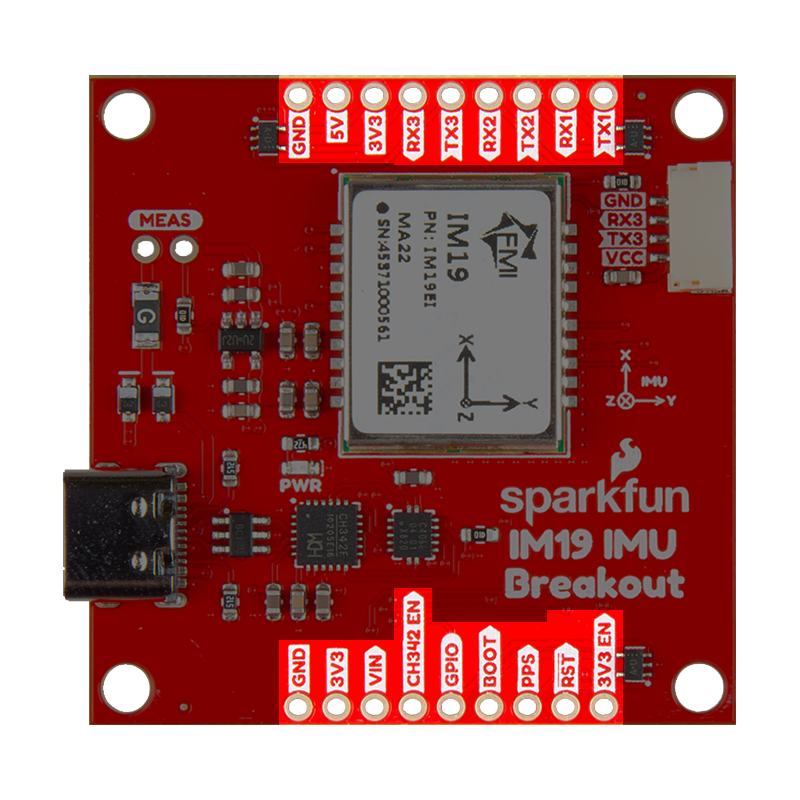
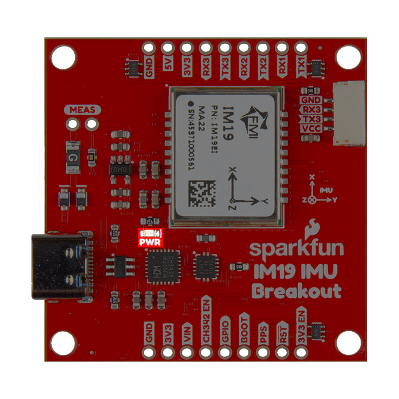
The SparkFun 9DoF IMU Breakout - IM19 features the following:
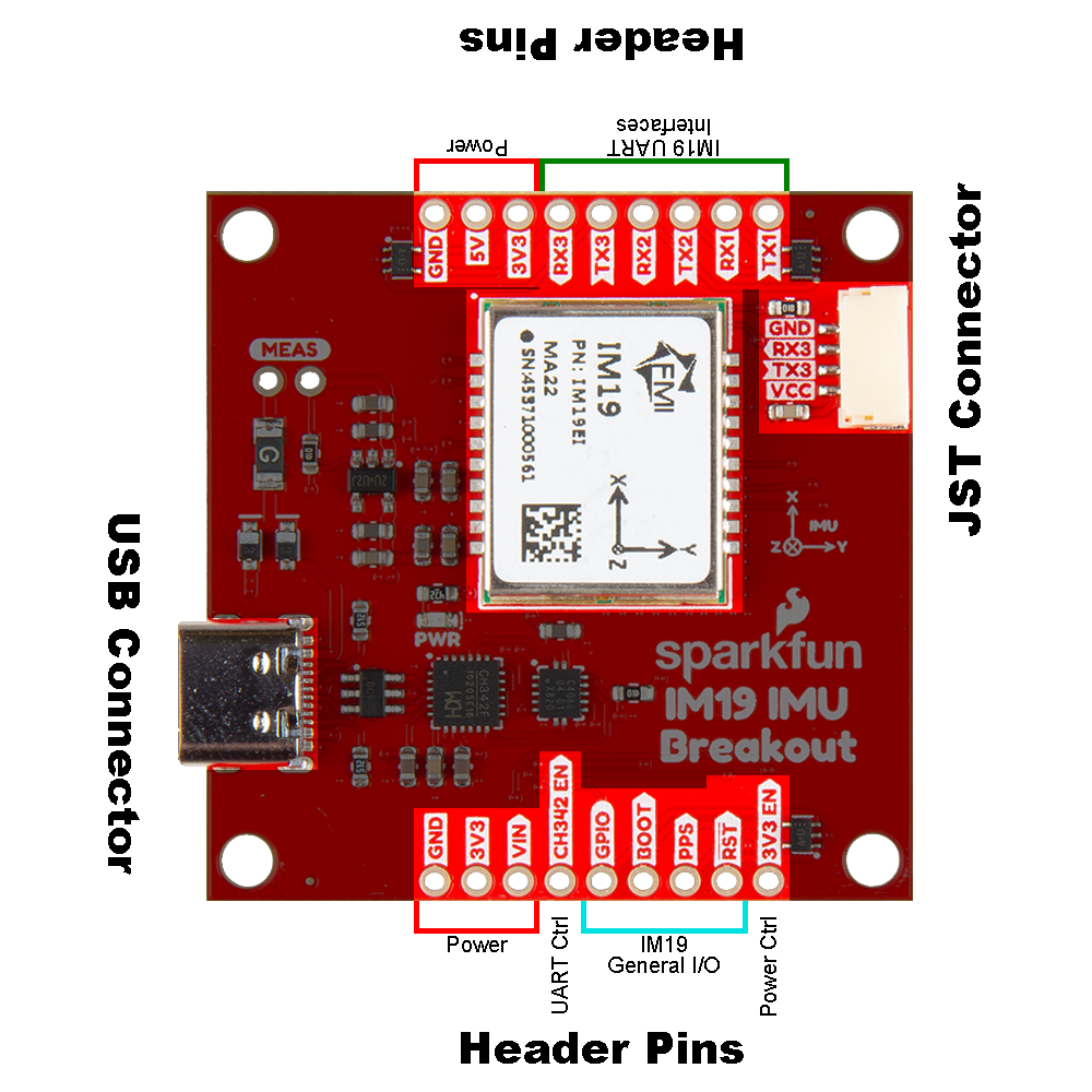
- USB-C Connector : The primary inteface for powering and interacting with the board
- IM19 Attitude Module : The Feyman IM19 Attitude Module
- Header Pins : Exposes pins to power the board and breaks out the interfaces of the IM19 attitude module
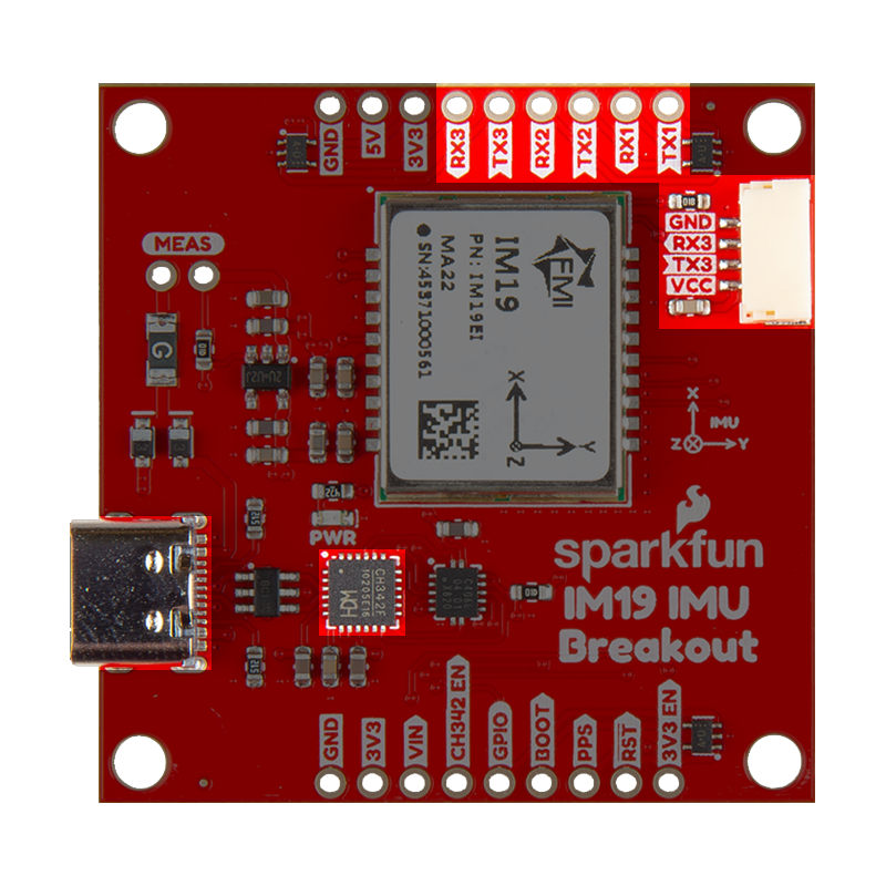
- JST Connector
: Exposes the
UART3interface of the IM19 attitude module
USB-C Connector
The USB connector is provided to power and interface with the IM19 attitude module. For most users, it will be the primary method for communicating with the IMU.
CH342 Converter
The CH342 serial-to-USB converter allows users to interface with the UART1 and UART2 ports of the IM19 attitude module through the USB-C connector. The breakout board also includes a digital switch, to isolate the CH342 and allow users to access these UART ports through their breakout pins. To utilize the CH342, users may need to install a USB driver, which can be downloaded from the manufacturer website. Once the USB driver is installed:
- Two virtual
COMports will be emulated, which can be used as standardCOMports to access the IM19 attitude module.Channel A:UART1of the IM19 attitude moduleChannel B:UART2of the IM19 attitude module
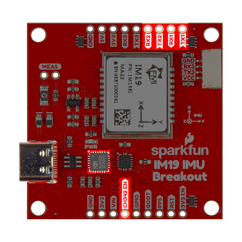
To activate the digital switch and utilize the UART ports through their breakout pins, users can close the CH342 EN jumper or pull theCH342 EN pin LOW. This disables the CH342 and disconnects the CH342 from the UART1 and UART2 ports of the IM19 attitude module, avoiding any bus contention issues.
- Windows: Download Page for
CH343SER.EXE - MacOS: Download Page for
CH341SER_MAC.ZIP
A USB driver is not required for Linux based operating systems.
Power
The IM19 breakout board only requires 3.3V to power all of the board's components. The simplest method to power the board is through the USB-C connector. Alternatively, the board can also be powered through the other connectors and PTH pins.
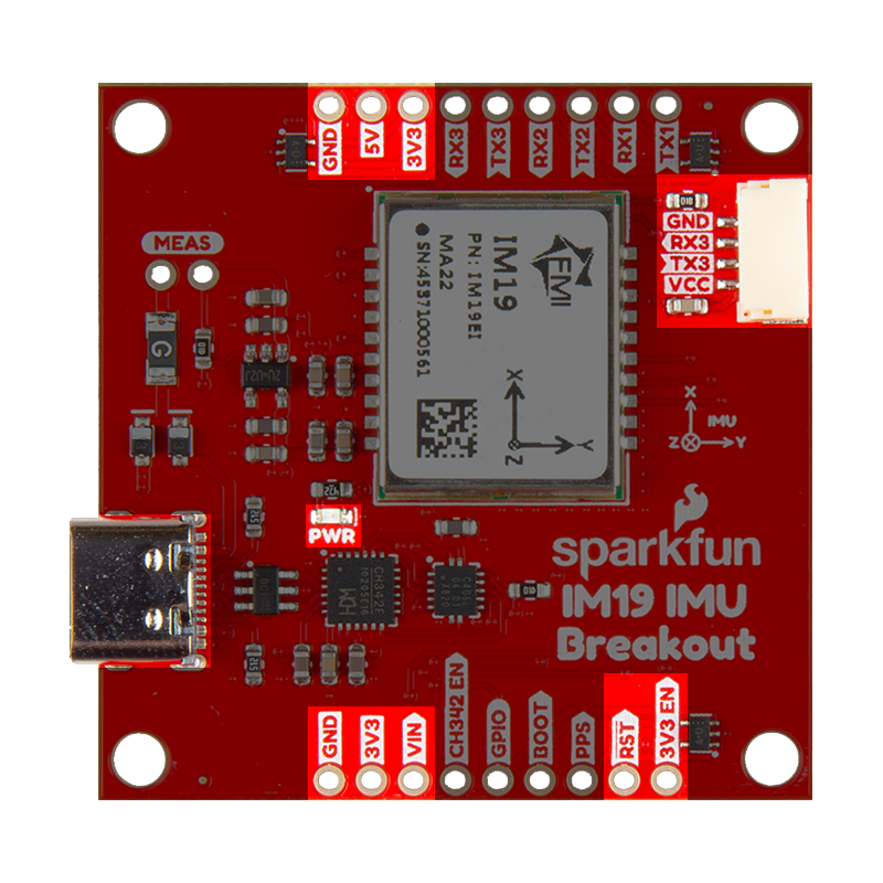
Below, is a general summary of the power circuitry on the board, broken out as PTH pins:
VUSB- The voltage from the USB-C connector, usually 5V- Input Voltage Range: 4.4 - 5.5 V
- Power source for the entire board
- Powers the 3.3V voltage regulator (RT9080), which can source up to 600mA
- When enabled, it can also power the JST connector (see the Jumpers section)
VIN- Alternate input supply voltage for the board- Input Voltage Range: 3.5 - 5.5V
- Power source for the entire board
- Powers the 3.3V voltage regulator (RT9080), which can source up to 600mA
- When enabled, it can also power the JST connector (see the Jumpers section)
3V3- Provides a regulated 3.3V from the RT9080, using the power supplied from theVINpin or USB-C connector- Used to power the IM19 module,
PWRLED, and the power pin of the JST connector - Controlled by the
3V3 ENpin, which is enabled by default
- Used to power the IM19 module,
3V3 EN- Enables the voltage output from the RT9080, 3.3V voltage regulator- Enabled by default (active
HIGH)
- Enabled by default (active
RST- Used to reset the IM19 attitude module- Driving the pin
LOWfor 10ms triggers a restart of the IM19 module
- Driving the pin
GND- The common ground or the 0V reference for the voltage supplies
While the RT9080 LDO regulator has an input voltage range of 1.2 - 5.5V, a minimum supply voltage of 3.5V is recommended for a 3.3V output.
The VCC pin of the of the JST connector is designed to operate as a voltage output. An input voltage can be supplied through the connector; however, users should be mindful of any voltage contention issues. Additionally, users can modify the VCC jumper to change the output voltage level of these pins.
For more details, users can reference the schematic and the datasheets of the individual components on the board.
IM19 Attitude Module
The IM19 attitude module from Feyman Inc. (FMI) fuses MEMS IMU sensor data and GNSS RTK positioning to deliver high-precision attitude compensated measurements, with roll and pitch accurate to within 0.05 degrees. This kind of superb accuracy has widespread uses in industrial applications such as tilt RTK surveys (where RTK poles need not be held straight vertical as the IM19 can calculate a virtual digital level at any tilt angle), agriculture machine automation, and dead reckoning.
Features:
- Power: 0.33W
- Voltage Range: 3.0 to 3.6V
- Current Consumption: 120 to 140mA
- Data Rate: 100Hz
- IMU Accuracy: ≤1% * D (1σ, vehicle)
- Roll and Pitch: ≤0.02° (1σ)
- Heading/Yaw: ≤0.2° (1σ)
- Initialization: 1s (95%)
- Gyroscope
- ARW: 0.17°/√(h)
- Bias Stability: ±4.5°/h
- Range: ±1000°/s
- Accelerometer
- Speed RW: 0.04m/s/√(h)
- Bias Stability: ±0.3mg
- Range: ±16g
- Self-calibration Technique
For more information, please refer to the IM19 datasheet.
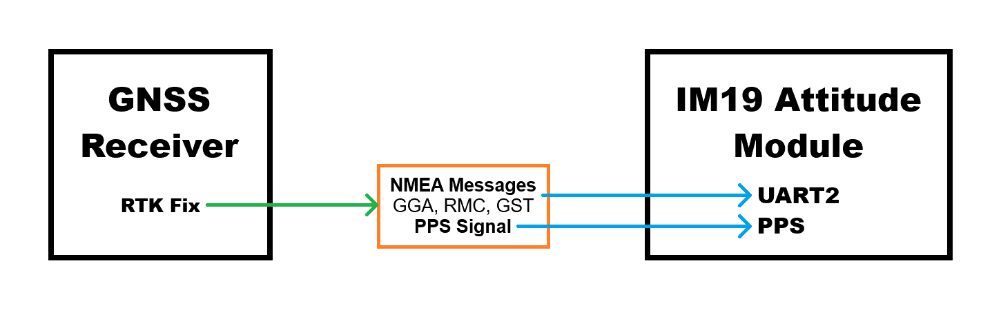
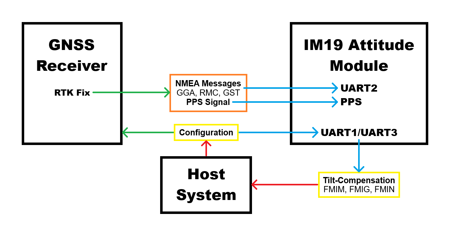
Tilt-Compensation
In order to provide a tilt-compensated position, the IM19 attitude module requires the Pulse-Per-Second signal; receive NMEA GGA, RMC and GST messages on its UART2 port, from a GNSS receiver with an RTK Fix; and be configured with information on the location of the GNSS antenna's reference center (ARC) and the survey point, with respect to the IMU's origin. Once calibrated, the IM19 will output proprietary FMI* messages containing the compensated position and roll, pitch and yaw attitudes.
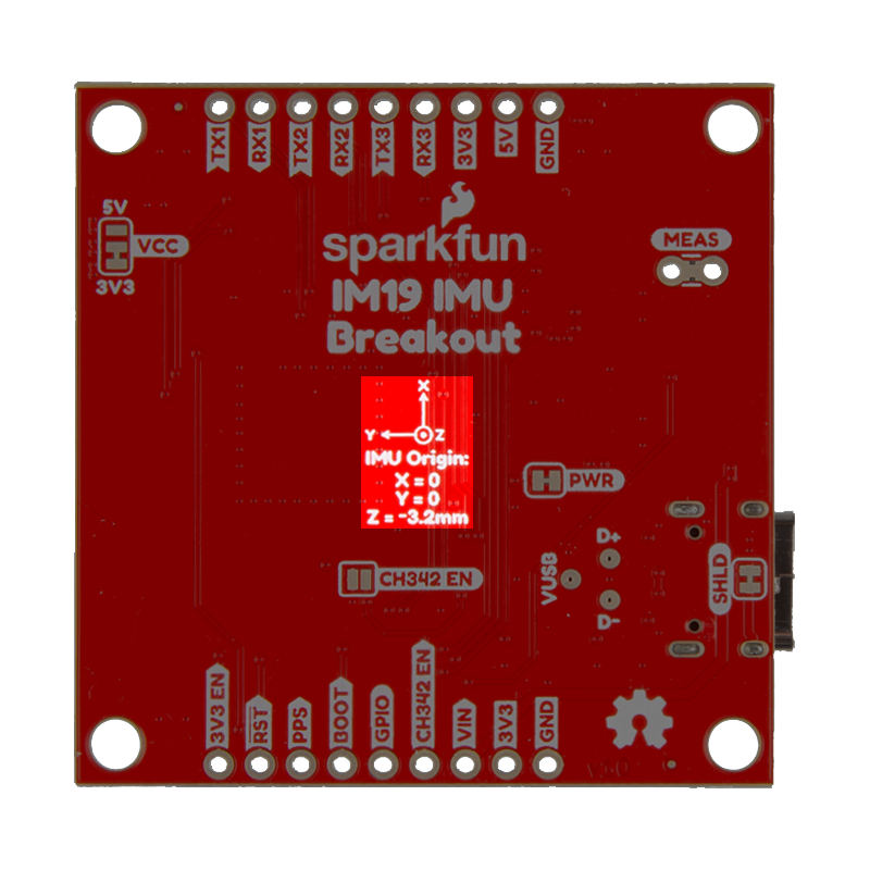
IMU Position
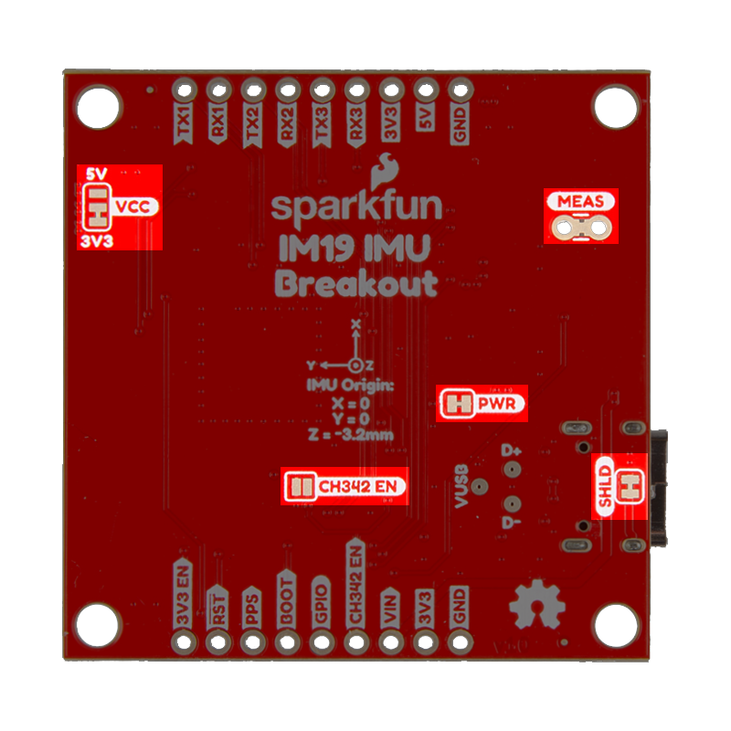
The measurements below are general guidelines for the position of the IMU inside the IM19 attitude module, with respect to the breakout board. The origin for the IMU is 2.72mm in Y-axis and 5.72mm in X-axis from the center of the IM19 attitude module. The plane of the Z-axis lies in the middle of IM19 attitude module, on the top surface of the module's PCB. In respect to the IM19 attitude module, which has a height of 3.2±0.1mm, the plane is located 1.6mm in towards the bottom/backside of the board from its top surface.
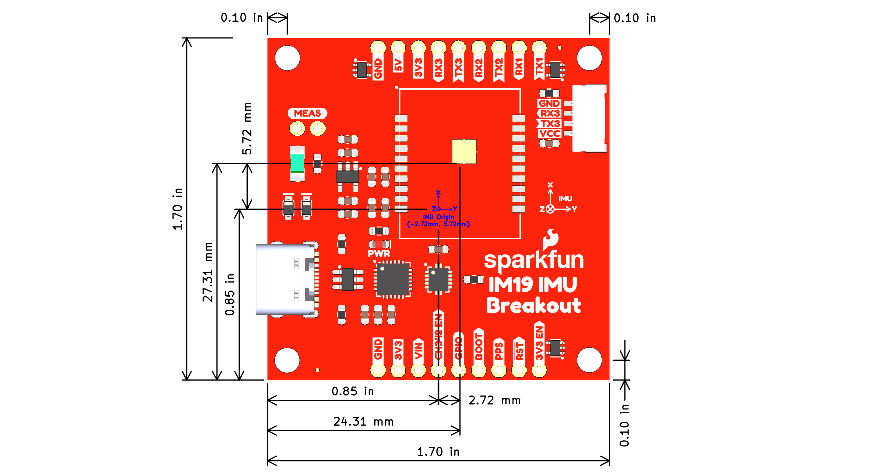
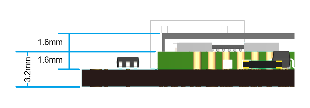
In reference to the breakout board, the IMU's origin on the X/Y-axes is centered in the middle of the PCB. A reference mark is provided on the bottom of the IM19 IMU breakout board. From the reference mark, the plane of the Z-axis is located 3.2mm towards the top/front of the board. For the most precise measurements, users should also consider the manufacturing tolerances for the board as the position/orientation of the IM19 attitude module may shift in the reflow process and the edges of the PCB may not be precise. The PSB is panelized for production, along the edges with the header pins using a v-score.
Lever Arm and Club Vectors
With the origin point of the IMU in the IM19 attitude module, users can determine the vector to the LEVER_ARM. This vector runs from the origin point of the IMU to the ARP (antenna reference point) of the GNSS antenna. The CLUB_VECTOR runs from the APC (antenna phase center) of the GNSS antenna to the surveying marker point. Both the CLUB_VECTOR and LEVER_ARM vectors need to be configure in the IM19 attitude module before it can be calibrated.

CLUB_VECTOR and LEVER_ARM vector. (Source: Septentrio)
Calibration & Initialization
Once the IM19 attitude module has been configured, it must go through an initialization process to calibrate the module. As demonstrated in the videos below, user need to give the IM19 attitude module a vigorous shake to initialize the calibration process. Once initialized, users need to:
- Shake to initialize calibration
- Swing the module back and forth (3-5sec)
- Rotate the device 90°
- Swing the module back and forth (3-5sec)
- Done
Accuracy
When configured and calibrated, the IM19 attitude module can fuses IMU sensor and GNSS RTK positioning data to deliver compensated position. The accuracy, displayed in the table below, should also be considered when implemented.
| Tilt Angle | Accuracy |
|---|---|
| 0° - 30° | 1cm |
| 30° - 60° | 2cm |
It is recommended that the IM19 module is placed in a stable temperature region and avoid convection with the outside air.
I/O Pins
The headers on the board, breakout the I/O pins of the IM19 attitude module. The UART interfaces of the IM19 are also connected to the CH342 USB-to-serial converter and JST connector on the board.
Pin Functions
Below is a summary of these I/O pins and their operation:
BOOT- Start modesHIGH: Boot modeNCorLOW: Normal working mode- Operation: Pulling the
BOOTpinHIGH, when powering up the module enables boot mode. This is used to update the module's firmware
RST- Hardware reset pin- Operation: Pulling the
RSTpinLOWfor 10ms, will reset module
- Operation: Pulling the
GPIO- Output IO- Function: Active buzzer can be connected
- UART Interfaces:
- Baud rate: 115200bps
- Operation: Configuration, message output, and firmware upgrade
- Configuration: See UART interface section
- Default Setting:
UART2- Connect GNSS boardUART1/UART3- Connect to host device
- Default Setting:
PPS- Connect to the PPS signal from the GNSS board- Function: Synchronizes the MEMS IMU sensor data with the GNSS RTK position data
- Configuration: See PPS signal section
- Default Setting: Falling edge
Header Pins
The headers on the board, breakout the I/O pins of the IM19 attitude module, the power pins, UART interfaces, and CH342_EN UART control pin.
UART Interfaces
The three UART interfaces of the IM19 attitude module are broken out to the header pins on the board, the JST connector, and connected to the CH342 USB-to-serial converter. By default, UART1 and UART2 interfaces are attached to the CH342 USB-to-serial converter and are accessed through the USB connector. To utilize the UART1 and UART2 interfaces through their header pins, user need to toggle the CH342_EN pin or close its jumper. This disables the CH342 USB-to-serial converter and a digital switch disconnects the UART interfaces to avoid any bus contention issues. Whereas, the UART3 interface can be accessed through either the JST connector or its header pins. The baud rate for the UART ports is not configurable and are set to 115200bps.
The UART ports are configured through AT-commands, which are summarized below. However, it should be noted that the baud rate of the ports cannot be configured. By default, the baud rate is hard-coded to 115200bps.
- Baud Rate: 115200bps
- AT-Commands:
AT+NAVI_OUTPUT=<Port>,<Output>- Enable the binary NAVI positioning output on the UART portAT+NASC_OUTPUT=<Port>,<Output>- Enable the ASCII type NAVI positioning output on the UART portAT+MEMS_OUTPUT=<Port>,<Output>- Enable the MEMS raw output on the UART portAT+GNSS_OUTPUT=<Port>,<Output>- Enable the GNSS raw output on the UART portAT+GNSS_PORT=PHYSICAL_<Port>- Sets the UART port for receiving the GNSS RTK data- Save the settings and restart the device to take effect
AT+LOOP_BACK=<Loop>- UART port enters or exits the loopback modeAT+OUTPUT_DISABLE=<Port>- Disables all output messages from the UART port- Where the
<values>above should be:<Port>=UART1,UART2, orUART3<Loop>=UART1,UART2,UART3, orNONE<Output>=ONorOFF
By default, the UART2 port is configured to receive the GNSS data required for the tilt-compensation. Whereas the default configuration of the UART1 and UART3 ports, the ports have the same functions. They can be connected to the main processor an/or used as a debugging, firmware upgrade, or configuration interface.
UART1- Connect to host device- Configuration, message output, and firmware upgrade
UART2- Connect GNSS boardUART3- Connect to host device- Configuration, message output, and firmware upgrade
For the UART interface sending the GNSS messages to the IM19 breakout board, users will need to configure the UART port with the following settings:
- Baudrate: 115200bps
- Output NMEA Messages:
GPGGA,GPRMC, andGPGST - Solution Rate: 5Hz
PPS Pin
The PPS pin needs to be connected to the PPS signal from the GNSS receiver. It is utilized to synchronizes the MEMS IMU sensor data with the GNSS RTK position data. When connected, the AT+CHECK_SYNC AT-command can be used to verify if the IM19 attitude module is synchronized with the GNSS RTK position data.
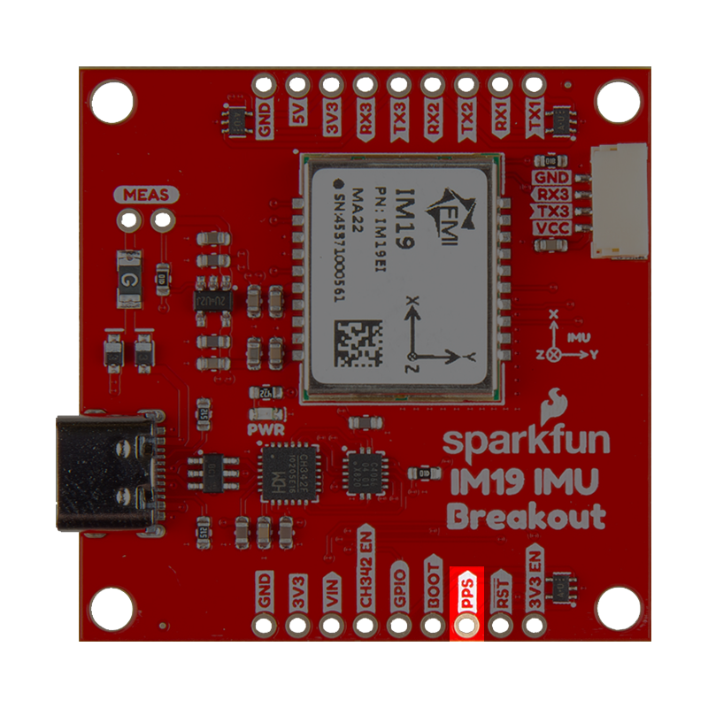
PPS pin on the IM19 breakout board.
The AT+SET_PPS_EDGE AT-command configures the edge detection parameter for the PPS signal. By default, the IM19 attitude module is configured to detect the falling-edge of the PPS signal.
Boot/RST Pins
The BOOT and RST pins are, respectively, used to update or reset the IM19 attitude module.
- The
BOOTpin can be toggledHIGH, when powering up the IM19 breakout board. This enables boot mode to update the IM19 attitude module's firmware through the UART interface. - The
RSTpin can be pulledLOWfor 10ms to IM19 attitude module.
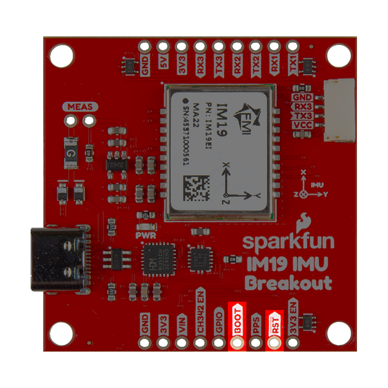
BOOT and RST pins on the IM19 breakout board.
GPIO Pin
The GPIO pin is an ouput pin; its suggested use is an audio indicator, with a connected buzzer.
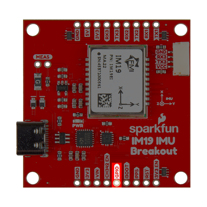
GPIO pin on the IM19 breakout board.
JST Connector
The JST-GH connector is used to access the UART3 interface. Its pin layout is labeled on the board and listed in the diagram below. The power supply for the VCC pin can be configured using the VCC jumper on the bottom of the board. By default, the jumper is configured to supply 3.3V to the JST connector.
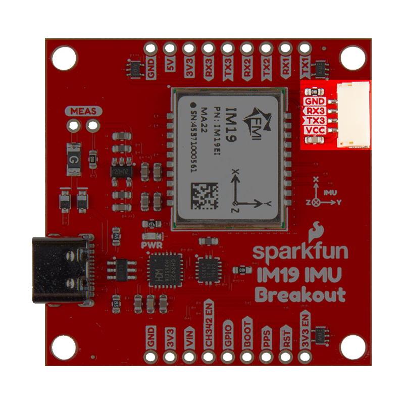
When connecting the IM19 breakout board to other products, users should be aware of the pin connections between the devices. The table below, details the pin connections of the locking JST connector on the IM19 breakout board.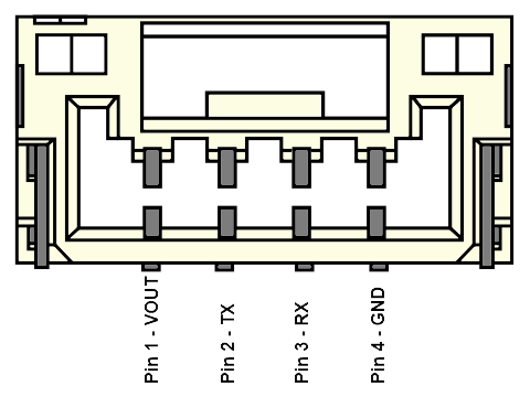
| Pin Number | 1 | 2 | 3 | 4 |
|---|---|---|---|---|
| Label | VCC | TX3 | RX3 | GND |
| Function | Voltage Output
| UART3 - Receive | UART3 - Transmit | Ground |
Users will need to configure the baud rate of the attach devices to match the UART port of the IM19 attitude module, which are set to 115200bps.
Status LEDs
There is a red PWR status LED on the IM19 breakout board, which indicates when the board is powered. It turns on once 3.3V power is supplied to the board
PWR status LED indicator on the IM19 breakout board.
Jumpers
Check out our Jumper Pads and PCB Traces tutorial for a quick introduction!
There are five jumpers on these board that can be used to easily modify the hardware connections.
SHLD- This jumper can be cut to disconnect the shield of the USB-C connector from the board's ground plane.PWR- This jumper can be cut to remove power from the red, power LED.MEAS- This jumper can be cut to to measure the current coming into the board from the USB connector orVINpin.VCC- This jumper can be modified to configure/disconnect theVCCpin of the 4-pin locking JST connector to/from3V3or5Vpower.- By default, the jumper is configured to supply 3.3V.
CH342_EN- This jumper can be closed to disable the CH342 and disconnect it from theUART1andUART2ports of the IM19 attitude module.- Allows the breakout pins to be utilized; avoiding bus contention issues.