Hardware Hookup
In this section, we will go over how to connect to the Qwiic Navigation Switch.
Connecting Via Qwiic
Insert a Qwiic cable between your Arduino microcontroller and the Qwiic Navigation Switch. In this case, we used the SparkFun IoT RedBoard - ESP32 Development Board for the Arduino microcontroller. When ready, connect a USB cable to the Arduino to program, power, and view serial messages.
Connecting via PTH
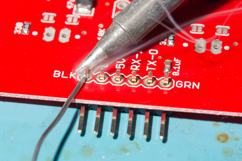
For temporary connections to the PTHs, you could use IC hooks to test out the pins. However, you'll need to solder headers or wires of your choice to the board for a secure connection. You can choose between a combination of header pins and jumper wires, or stripping wire and soldering the wire directly to the board.
Interrupt
For users that want to notify the microcontroller that the switch is pushed toward a direction, you could connect the INT pin to one of the Arduino's interrupts. In this case, we connected the Navigation Switch's INT pin to the IoT RedBoard's pin 4.
Note
Example 3 from the SparkFun I2C Expander Arduino Library uses the IoT RedBoard - ESP32's pin 14 for the interrupt. The example in this tutorial is slightly different and uses pin 4 for the interrupt.


