Quick Start Guide
In this Quick Start guide we'll go over how to assemble a single AC load to the Qwiic Relay 1X1A - DPDT and connect it to a SparkFun RedBoard IoT - ESP32 to control the relay and load using the SparkFun I2C Expander Arduino Library.
This Quick Start guide assumes users have an understanding of how to safely wire an AC load to a relay, how to use Qwiic breakouts with Arduino development boards and how to use the Arduino IDE. If you're not familiar with these concepts we recommend reading through the rest of the guide before proceeding to assemble the Qwiic Relay.
Qwiic Assembly
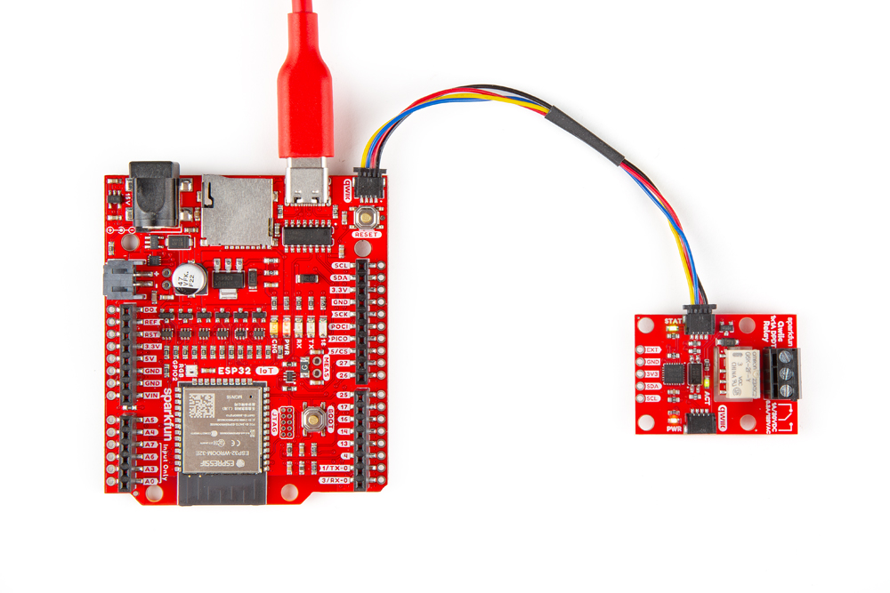
We'll start by connecting the Qwiic Relay 1X1A - DPDT to the RedBoard IoT - ESP32 using a Qwiic cable. Simply plug one end into one of the Qwiic Relay's Qwiic connectors and the other into the RedBoard IoT's Qwiic connector like the photo below:
Relay Load Assembly
Not sure about what color insulation wiring is used in you region? Check out the standard wire insulation colors listed online for reference. If you are unsure about the standard wiring color in your region, please consult a certified electrician to connect to the AC input voltage side. Make sure the cable is not plugged into the wall as you cut into the wire in the following section.
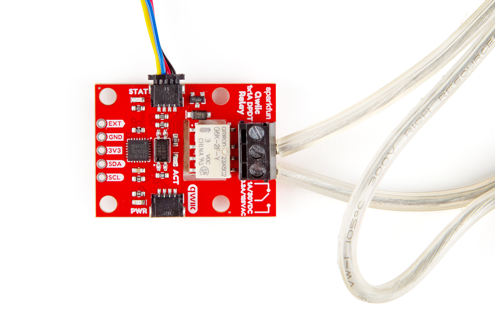
With the Qwiic Relay 1x1A connected to the RedBoard, let's prepare the wiring for the AC load with the following steps:
- Start by cutting the live AC line (usually black or red) and stripping a small amount of insulation away from the ends of the cut wire.
- Insert one end of the cut wire into the
COMscrew terminal and tighten it to secure the wire. - Insert the other end of the cut wire either into the
NCorNOscrew terminal depending on whether the device will normally be on or off.- If the device will normally be on and switched off, connect this end to
NC. - If the device will normally be off and switched on, connect this end to
NO.
- If the device will normally be on and switched off, connect this end to
Warning! Make sure that your wires connecting to the wall outlet are secure and are rated to handle the current! Please be careful when handling the contacts when the cable is plugged into a wall outlet. Touching the contacts while powered could result in injury.
Looking for information about safety and insulation? Check out the notes about Safety and Insulation from our Beefcake Relay Control Kit.
With everything connected up, your circuit should look similar to the photo below. Now let's upload some code to turn the load on and off.
Toggle Relay LED Arduino Example
This example toggles the relay and both green status LEDs on and off every second. This example uses the SparkFun I2C Expander Arduino Library and can be found in the Examples folder of the Qwiic Relay Line GitHub repository. Follow the steps below to upload the code.
- Open the Arduino IDE.
- Open the Library Manager tool, search for "SparkFun I2C Expander" and install the latest version.
- Either download the example from the Examples folder of the Qwiic Relay Line library or copy the example code into a blank Arduino sketch.
- Select your Board (SparkFun RedBoard IoT - ESP32 or other board) and Port and click "Upload".
- After the code compiles and finishes uploading, the AC load and green LEDs should be turning on and off every second. You can open the serial monitor with the baud set to 115200 to view the serial printout of the code in case there are any errors.