Introduction
-
SparkFun RTK Postcard
SKU: GPS-26916


-
Designed and manufactured in Boulder, CO USA, the SparkFun RTK Postcard is a compact development board for your high-precision positioning and navigation needs. This board combines the Quectel LG290P GNSS RTK receiver with an Espressif ESP32-PICO-MINI-02 MCU module, running our latest RTK Everywhere firmware. The ESP32 provides the SparkFun Postcard with WiFi and Bluetooth™ connectivity to operate as an NTRIP caster or client. Meanwhile, the 4-pin locking JST-GH connector allows users to transmit or receive RTCMv3 messages for RTK corrections from a local base station.
-
The LG290P module is a quad-band, multi-constellation, high-precision, RTK GNSS receiver. The module can simultaneously receive signals from the
L1,L2,L5, andL6/E6frequency bands of the GPS, GLONASS, Galileo, BDS, QZSS, and NavIC GNSS constellations. In addition, the module supports SBAS augmentation systems (WASS, EGNOS, BDSBAS, MSAS, GAGAN, and SDCM), PPP services2 (BDS PPP-B2b, QZSS CLAS, MADOCA-PPP, and Galileo HAS), RTCM, and RTK corrections for precision navigation with a fast convergence time and reliable performance. Connect with ease using a variety of interfaces, including UART, SPI1, and I2C1. -
The ESP32-PICO-MINI-02 is a powerful MCU module with WiFi, Bluetooth™, and BLE connectivity and comes integrated with 8MB SPI flash, 2MB SPI Pseudo static RAM (PSRAM), and a 40 MHz crystal oscillator. The ESP32 microcontroller itself features two CPU cores that can be individually controlled, with an adjustable clock frequency between 80 - 240MHz and a low-power co-processor for minor tasks, such as monitoring peripherals. It supports a range of peripherals including an SD card interface, capacitive touch sensors, ADC, DAC, Two-Wire Automotive Interface (TWAI), Ethernet, high-speed SPI, UART, I2S, I2C, etc.
With the RTK Everywhere firmware that comes pre-loaded, users can seamlessly operate the RTK Postcard as a base station or rover. These modes also offer additional functions, based on the available, wireless communication options:
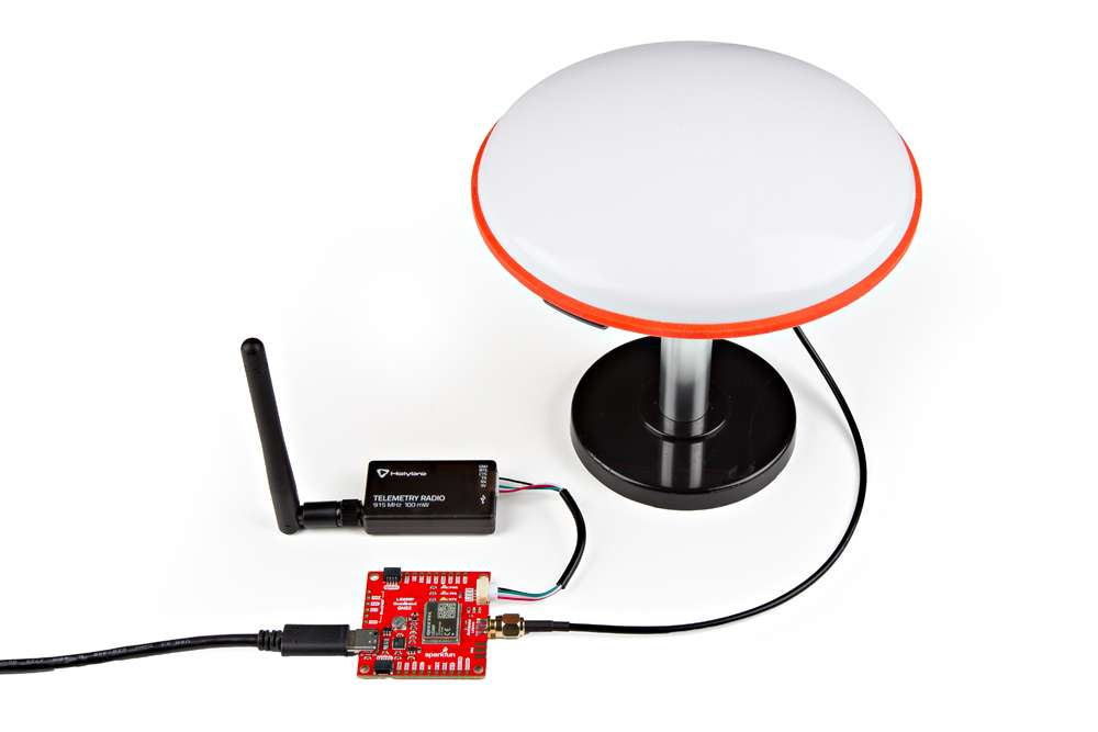
- The RTK Postcard can transmit or receive RTCMv3 messages locally by connecting one of our SiK Telemetry radios.
- Through WiFi or Bluetooth™, the RTK Postcard can also function as an NTRIP caster or client.
- The RTK Postcard can transmit NMEA messages to a graphical information software (GIS) apps on any mobile device when paired as a Bluetooth™ device.
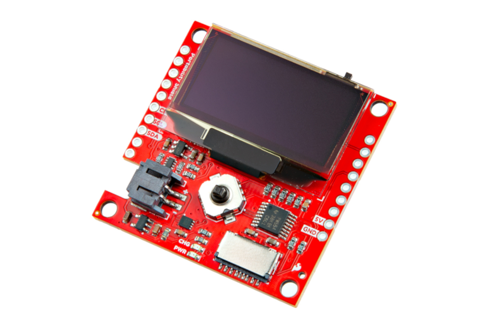
In addition to the RTK Postcard, we created the Portability Shield for the convenience of users. Simply connecting these products, provides a 1.3” OLED display and a five-way button to navigate the configuration settings and display PNT data; a microSD card slot for data logging; and a LiPo battery charger with a fuel gauge to take the RTK Postcard "on-the-go". All of these will operate plug-and-play without the need for new code.
Info
The RTK Everywhere firmware is open-source, so users can obtain, check, and even modify the device's functionality. This allows for easier feature expansion, bug maintenance, and longer device longevity.
-

Features Under Development
- I2C/SPI - Currently, only the UART interface is supported by the module.
- PPP Services - Corrections for some of the PPP services have not been implemented.
Required Materials
To get started, users will need a few items. Some users may already have a few of these items, feel free to adjust accordingly.
- Computer and/or mobile device that is compatible with the operation of the RTK Everywhere firmware
- USB 3.1 Cable A to C - 3 Foot - Used to power/interface with the SparkFun RTK Postcard (1)
- SparkFun RTK Postcard
- GNSS Multi-Band Antenna
- If your computer doesn't have a USB-A slot, then choose an appropriate cable or adapter.
-
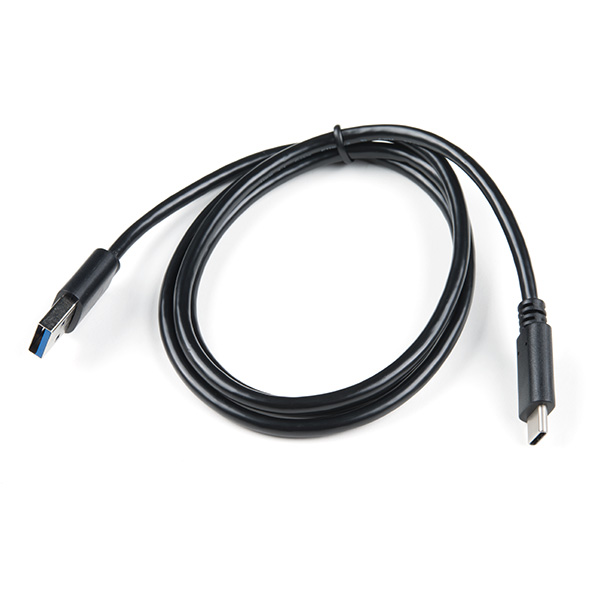
USB 3.1 Cable A to C - 3 Foot
CAB-14743 -
SparkFun RTK Postcard
GPS-26916
Recommended Accessories
These products are recommended at minimum for users to get started with the Portability Shield and RTK Everywhere firmware.
-
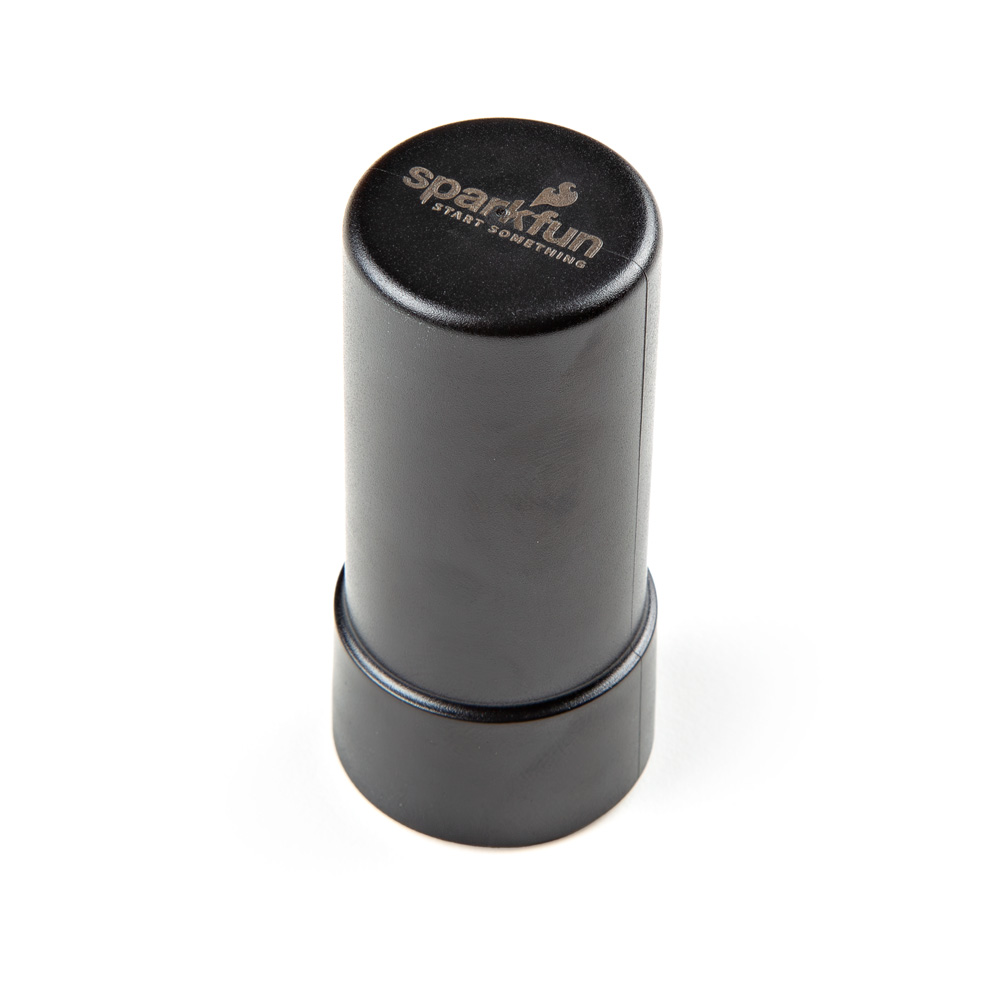
GNSS Multi-Band L1/L2/L5 Helical Antenna (SMA)
GPS-23847 -

SparkFun Portability Shield
DEV-27510 -
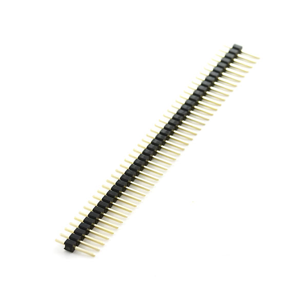
Break Away Headers - Straight
PRT-00116
Soldering Equipment
To add headers for the Portability Shield, users will need soldering equipment.
New to soldering?
Check out our How to Solder: Through-Hole Soldering tutorial for a quick introduction!
-

How to Solder: Through-Hole Soldering
-
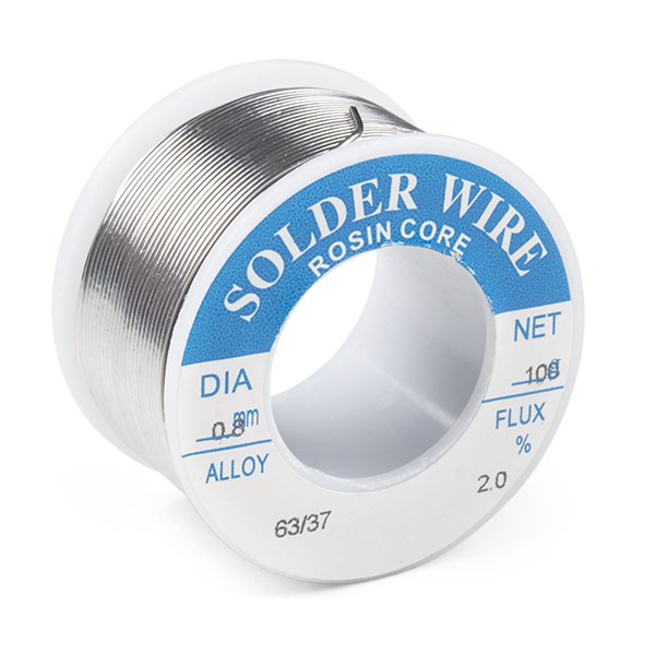
Solder Lead Free - 100-gram Spool
TOL-09325 -
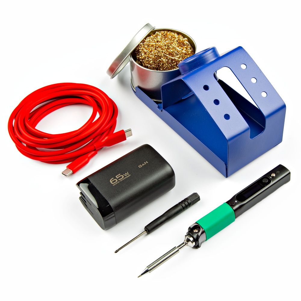
PINECIL Soldering Iron Kit
KIT-24063
Optional Accessories
These products are optional, based on the utility required by the user.
-
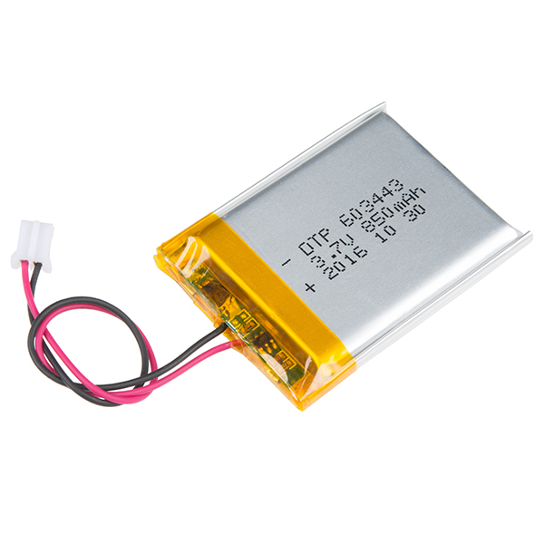
Lithium Ion Battery - 850mAh
PRT-13854 -
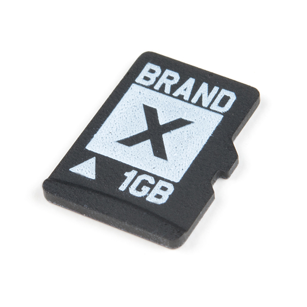
microSD Card - 1GB (Class 4)
COM-15107
GNSS Antennas & Accessories
For the best performance, we recommend users choose an active, multi-band GNSS antenna and utilize a low-loss cable. For additional options, please check out the GPS Antenna category of our product catalog.
-
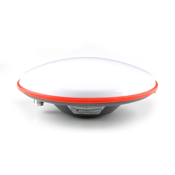
GNSS Multi-Band L1/L2/L5 Surveying Antenna - TNC (SPK6618H)
GPS-21801 -
GNSS Multi-Band L1/L2/L5 Helical Antenna (SMA)
GPS-23847 -
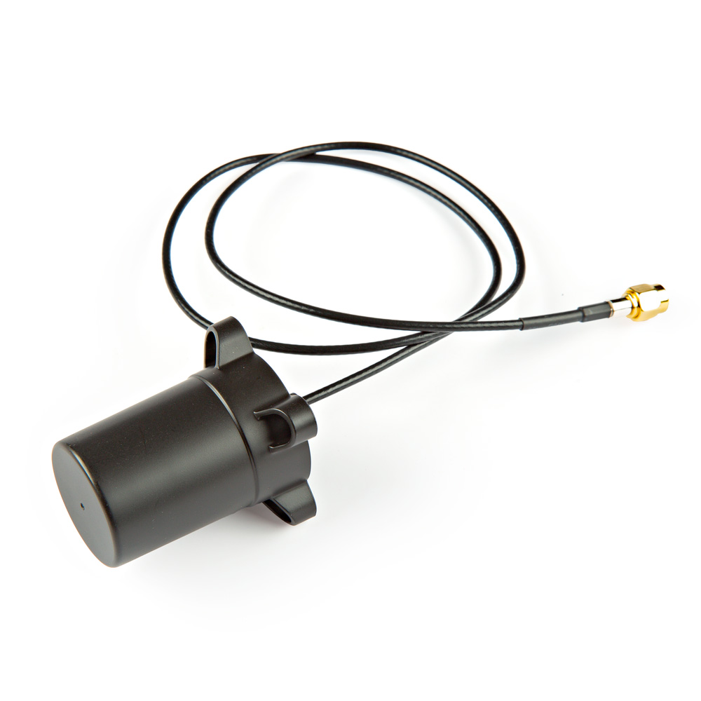
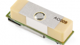
GNSS Multi-Band L1/L2/L5 Helical Antenna - SMA (BT-T009)
GPS-23848 -
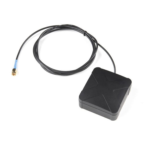
MagmaX2 Active Multiband GNSS Magnetic Mount Antenna - AA.200
GPS-17108
-
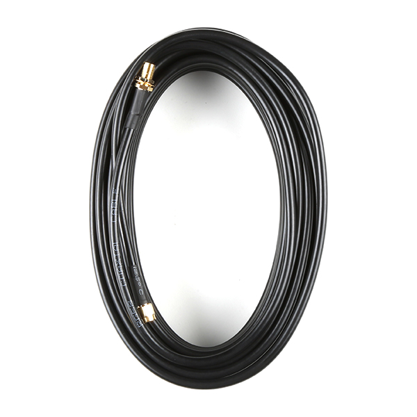
Interface Cable - SMA Female to SMA Male (10m, RG58)
CAB-21281 -
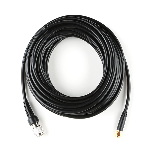
Reinforced Interface Cable - SMA Male to TNC Male (10m)
CAB-21740 -
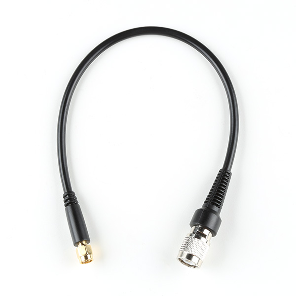
Reinforced Interface Cable - SMA Male to TNC Male (300mm)
CAB-21739
-
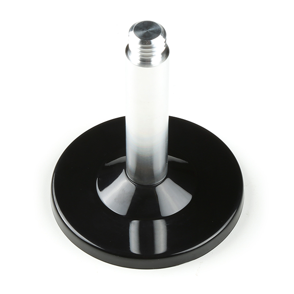
GNSS Magnetic Antenna Mount - 5/8" 11-TPI
PRT-21257 -
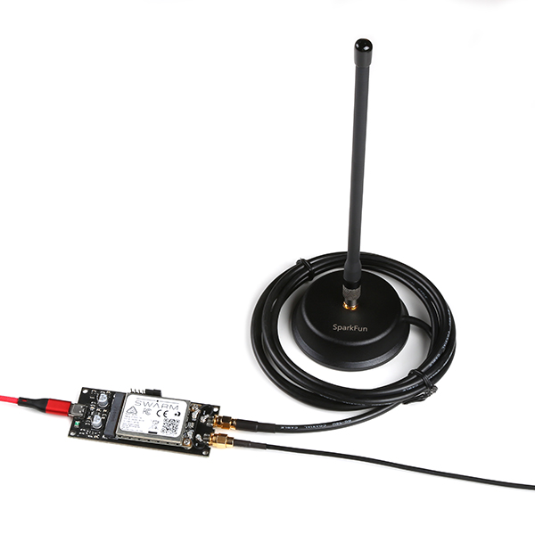
Magnetic Mount SMA - 2m
GPS-19576 -
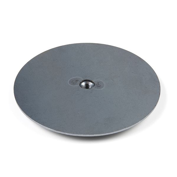
GPS Antenna Ground Plate
GPS-17519 -
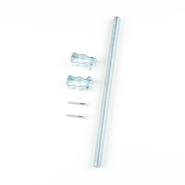
GNSS Antenna Mounting Hardware Kit
KIT-22197 -
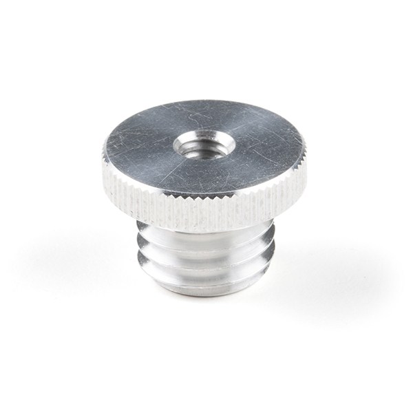
Antenna Thread Adapter - 1/4in. to 5/8in.
PRT-17546 -

Telescopic Surveying Pole
GPS-25795
Serial Transceivers, UART Adapters, and USB Cables
To configure the UART ports that are broken out on the board, users will need a UART adapter. Once configured, the UART ports can utilize one of our RF transceivers to send/receive RTCM messages.
-
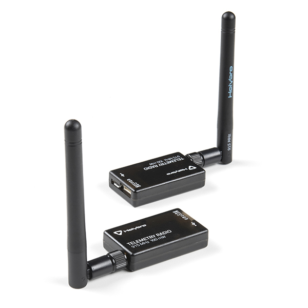
SiK Telemetry Radio V3 - 915MHz, 100mW
WRL-19032 -
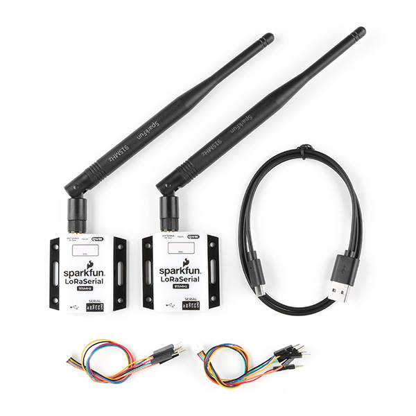
SparkFun LoRaSerial Kit - 915MHz (Enclosed)
WRL-20029 -
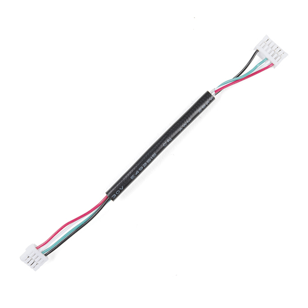
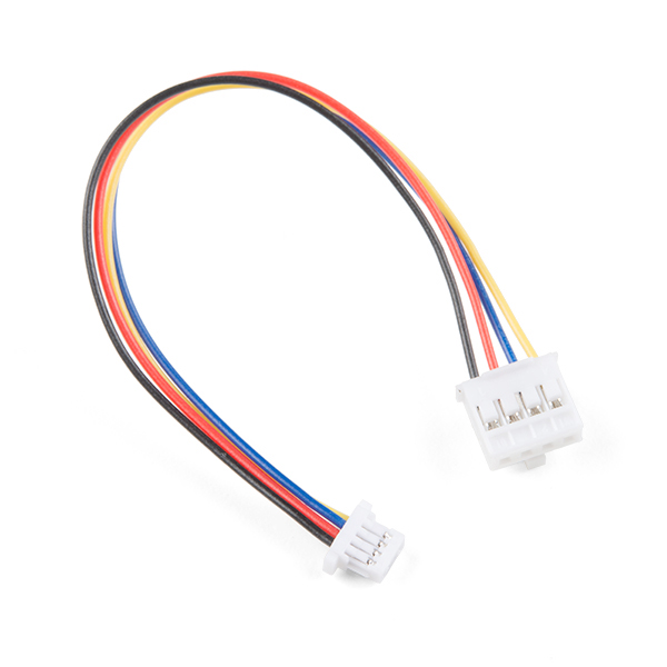
JST-GHR-04V to JST-GHR-06V Cable - 1.25mm pitch
CAB-17239 -
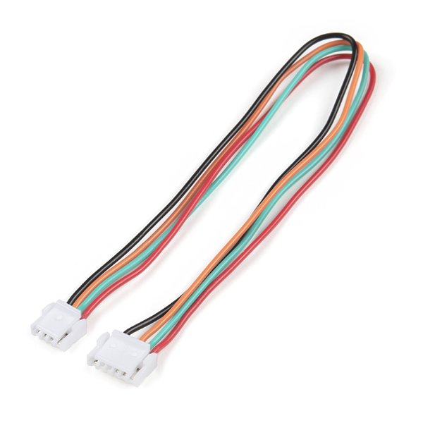
GHR-04V-S to GHR-06V-S Cable - 100mm
CAB-17854 -
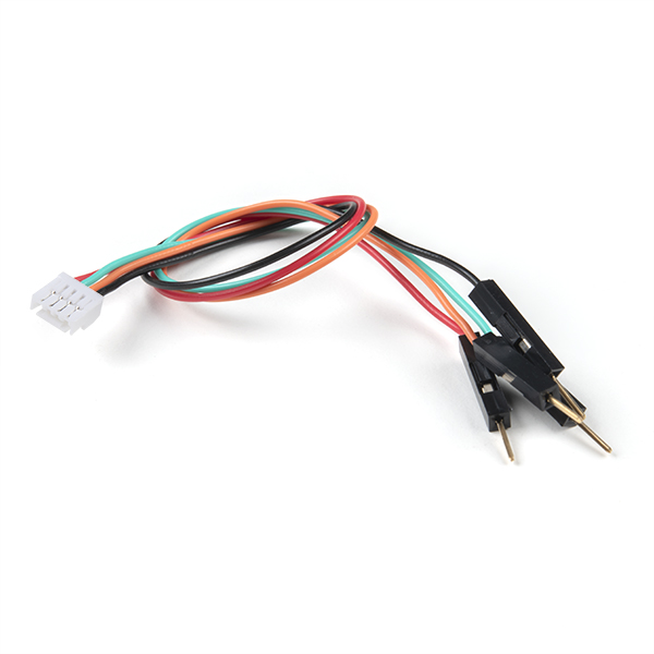
Breadboard to JST-GHR-04V Cable - 4-Pin x 1.25mm Pitch
CAB-17240
-
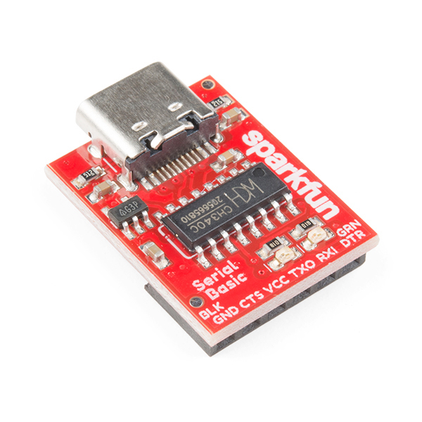
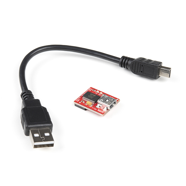
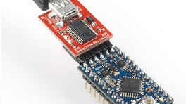
SparkFun Serial Basic Breakout - CH340C and USB-C
DEV-15096 -
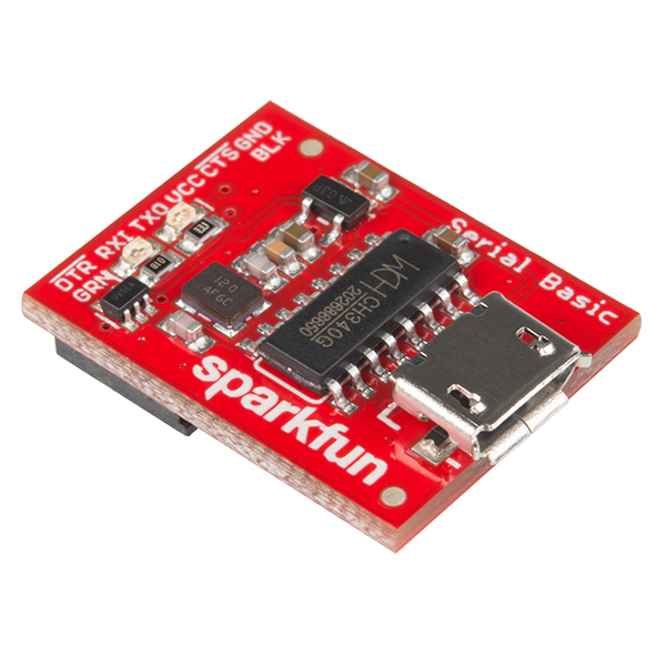
SparkFun Serial Basic Breakout - CH340G
DEV-14050 -
SparkFun FTDI Starter Kit - 3.3V
KIT-18289
-
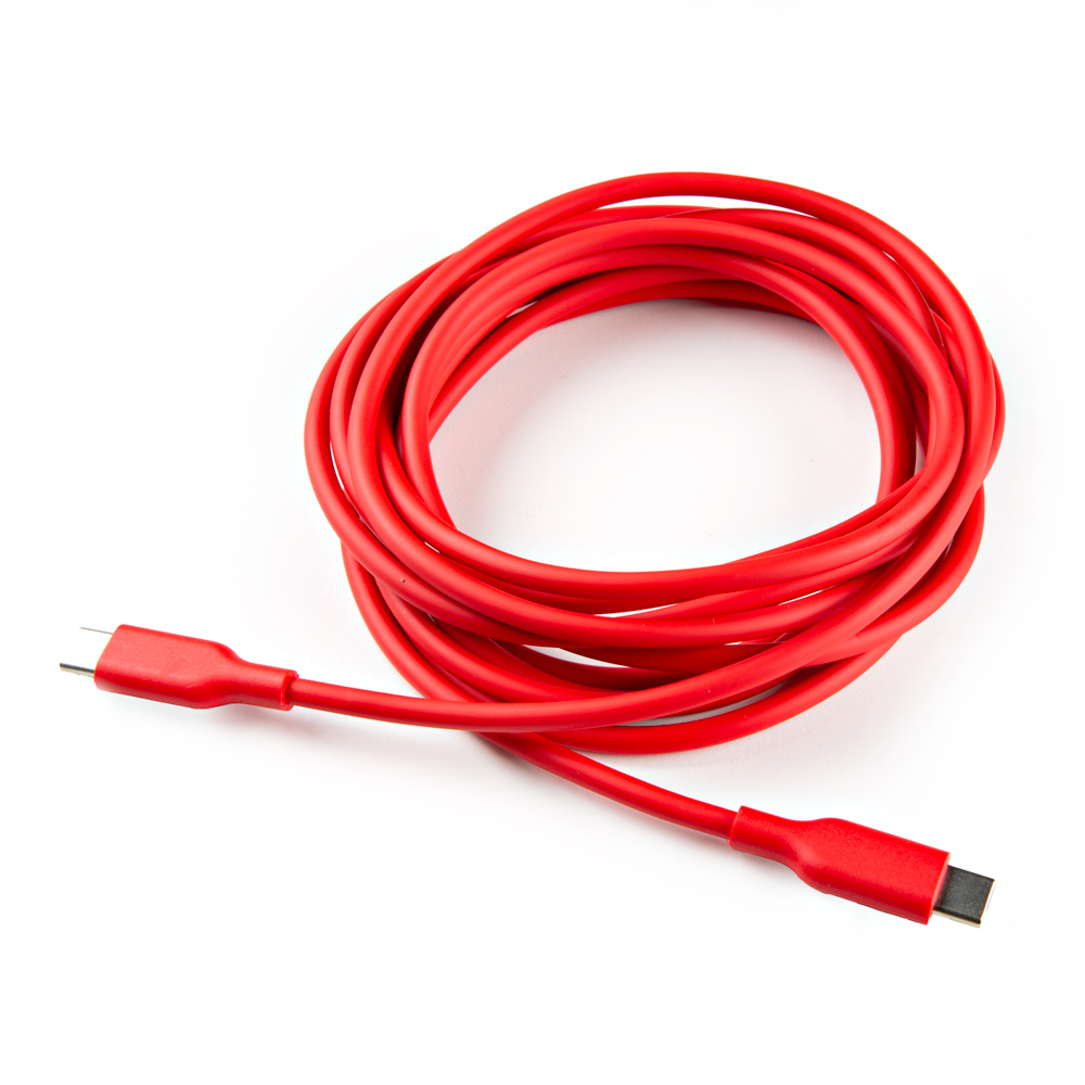
USB-C to USB-C Silicone Power Charging Cable - 3m
CAB-24060 -
USB 3.1 Cable A to C - 3 Foot
CAB-14743 -
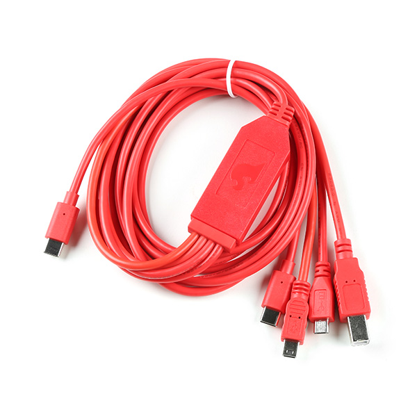
SparkFun 4-in-1 Multi-USB Cable - USB-C Host
CAB-21271 -
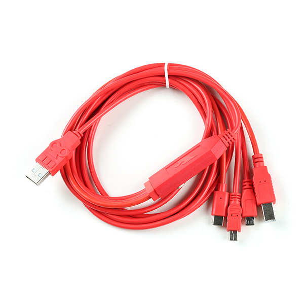
SparkFun 4-in-1 Multi-USB Cable - USB-A Host
CAB-21272
Shields, Headers, and Wiring
To add headers or wiring, users will need soldering equipment and headers/wires.
New to soldering?
Check out our How to Solder: Through-Hole Soldering tutorial for a quick introduction!
-
How to Solder: Through-Hole Soldering
-
Solder Lead Free - 100-gram Spool
TOL-09325 -

iFixit FixHub - Power Series Portable Soldering Station
TOL-27147 -
SparkFun Portability Shield
DEV-27510 -
Break Away Headers - Straight
PRT-00116 -

Header - 10-pin Female (PTH, 0.1")
PRT-11896 -
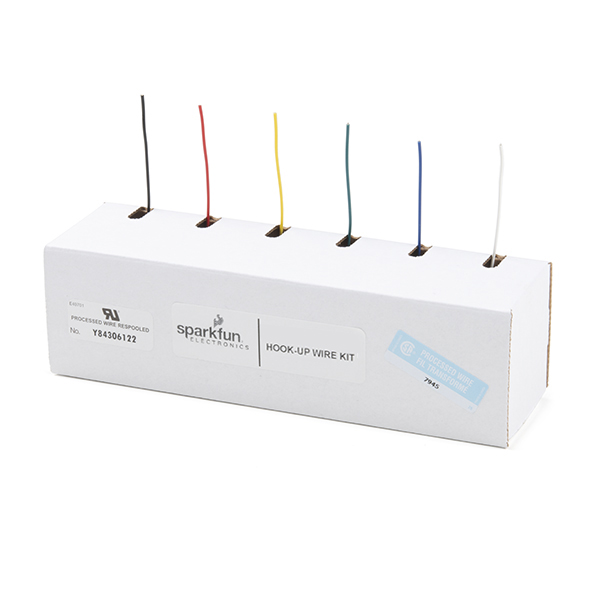
Hook-Up Wire - Assortment (Stranded, 22 AWG)
PRT-11375
Batteries
When using the Portability Shield, users can attach a single-cell LiPo battery to turn the boards into a mobile device.
Minimum Requirements
While users could probably discharge their LiPo batteries down to the maximum threshold of the battery's UVLO at 2.8V, the LG290P GNSS receiver and ESP32 MCU will discontinue operating, long before that can occur. We have found that the LG290P will begin to brown-out around 3.05-3.15V and the ESP32 will stop operating around 2.85-2.90V.
Therefore, users also won't be able to power this device with two 1.5V alkaline batteries (in series). They will require a minimum of three batteries to maintain an operational voltage, above 3. 15V.
The discharge rate of most single-cell batteries is 1C, unless specified otherwise.
Example
That means that the maximum current that can be expected from a battery is equal its capacity/hr. For instance, a 400mAh battery can be expected to handle a current draw of 400mA, at maximum.
-
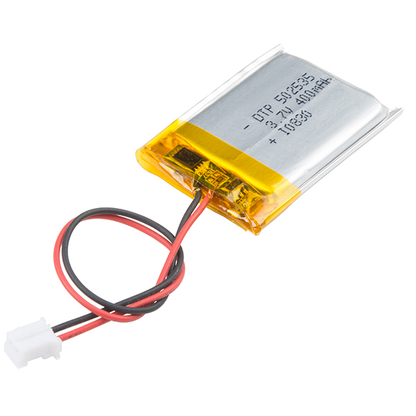
Lithium Ion Battery - 400mAh
PRT-13851 -
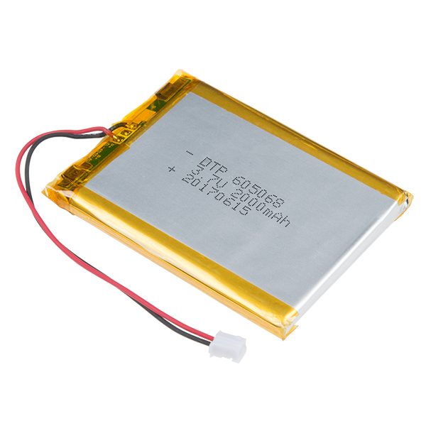
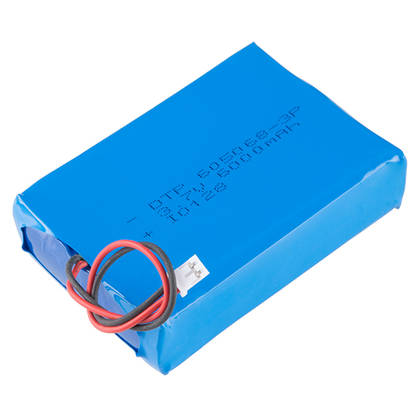
Lithium Ion Battery - 850mAh
PRT-13854 -

Lithium Ion Battery - 1500mAh (IEC62133 Certified)
PRT-26059 -
Lithium Ion Battery - 2Ah
PRT-13855 -
Lithium Ion Battery - 6Ah
PRT-13856 -
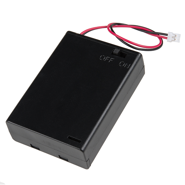
Battery Holder 3xAA with Cover and Switch - JST Connector
PRT-18769
Qwiic Devices and Cables
Our Qwiic connect system is a simple solution for daisy chaining I2C devices without the hassle of soldering or checking wire connections. Check out other Qwiic devices from our catalog.
-
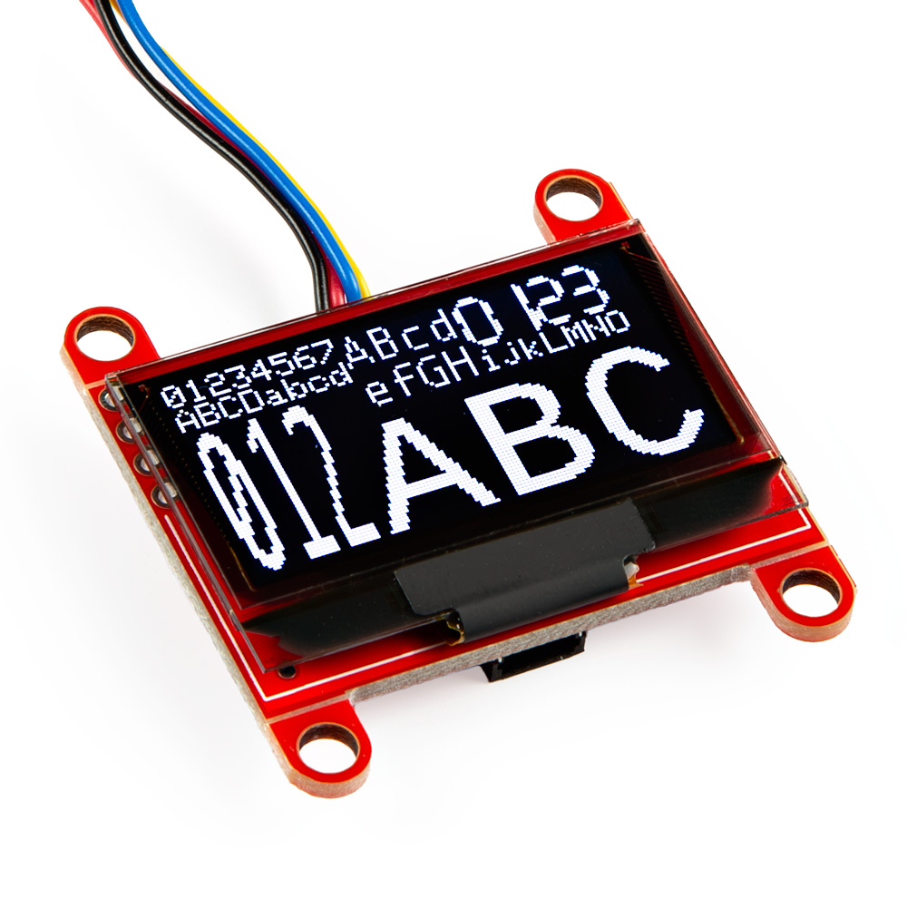
SparkFun Qwiic OLED - (1.3in., 128x64)
LCD-23453 -
SparkFun Qwiic Navigation Switch
PRT-27576 -

SparkFun Qwiic Directional Pad
PRT-26851 -
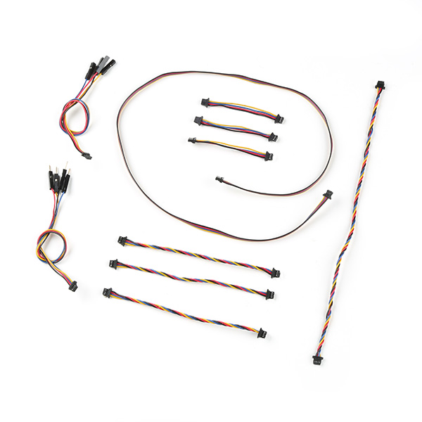
SparkFun Qwiic Cable Kit
KIT-15081 -
Qwiic Cable - Grove Adapter (100mm)
PRT-15109 -

SparkFun Micro Pressure Sensor - BMP384 (Qwiic)
SEN-19833 -

SparkFun Qwiic Button - Green LED
BOB-16842

What is Qwiic?
![]()
![]()
The Qwiic connect system is a solderless, polarized connection system that allows users to seamlessly daisy chain I2C boards together. Play the video, to learn more about the Qwiic connect system or click on the banner above to learn more about Qwiic products.

Features of the Qwiic System


Qwiic cables (4-pin JST) plug easily from development boards to sensors, shields, accessory boards and more, making easy work of setting up a new prototype.


There's no need to worry about accidentally swapping the SDA and SCL wires on your breadboard. The Qwiic connector is polarized so you know you’ll have it wired correctly every time.
The part numbers for the PCB connector is SM04B-SRSS (Datasheet) and the mating connector on the cables is SHR04V-S-B; or an equivalent 1mm pitch, 4-pin JST connection.


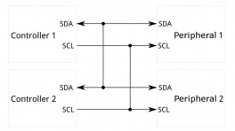
It’s time to leverage the power of the I2C bus! Most Qwiic boards will have two or more connectors on them, allowing multiple devices to be connected.
Jumper Modification
To modify the jumpers, users will need soldering equipment and/or a hobby knife.
New to jumper pads?
Check out our Jumper Pads and PCB Traces Tutorial for a quick introduction!
-

How to Work with Jumper Pads and PCB Traces
-
iFixit FixHub - Power Series Portable Soldering Station
TOL-27147 -
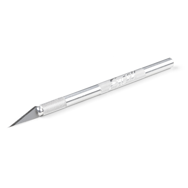
Hobby Knife
TOL-09200 -
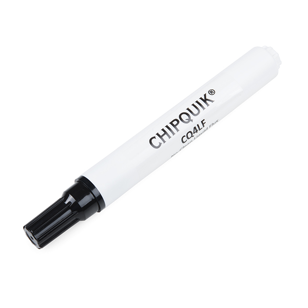
Chip Quik No-Clean Flux Pen - 10mL
TOL-14579 -

Solder Wick #2 5ft. - Generic
TOL-09327
Suggested Reading
As a more sophisticated product, we will skip over the more fundamental tutorials (i.e. Ohm's Law and What is Electricity?). However, below are a few tutorials that may help users familiarize themselves with various aspects of the board.
Tip
Check out the www.gps.gov website to learn more about the U.S.-owned Global Positioning System (GPS) and the Global Navigation Satellite Systems (GNSS) of other countries.
-
GPS Basics
-
What is GPS RTK?
-
Quadband GNSS RTK Breakout - LG290P (Qwiic) Hookup Guide
-
Portability Shield Hookup Guide
-
SparkFun RTK Everywhere Product Manual
-
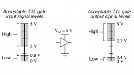
Logic Levels
-
Serial Communication
-
Serial Terminal Basics
-
I2C
-
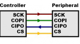
SPI
-
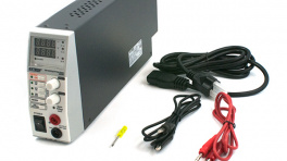
How to Power a Project
-
How to Solder: Through-Hole Soldering
-
How to Work with Jumper Pads and PCB Traces
Related Blog Posts
Additionally, users may be interested in these blog post articles on GNSS technologies:
-

GPS vs GNSS
-

What is Correction Data?
-

Real-Time Kinematics Explained
-
New Video: Unlocking High-Precision RTK Positioning
-

DIY RTK Surveying