Hardware Overview
Board Dimensions
The board dimensions are illustrated in the drawing below; the listed measurements are in inches.

Board dimensions (PDF) for the USB Host Shield, in inches.
Need more measurements?
For more information about the board's dimensions, users can download the Eagle files for the board. These files can be opened in Eagle and additional measurements can be made with the dimensions tool.
Eagle - Free Download!
Eagle is a CAD program for electronics that is free to use for hobbyists and students. However, it does require an account registration to utilize the software.
 Dimensions Tool
This video from Autodesk demonstrates how to utilize the dimensions tool in Eagle, to include additional measurements:

Power
The MAX3421E USB controller only requires 3.3V to operate; however, the shield (and USB-C connector) is powered entirely through either the 5V or VIN pins of the connected Arduino board.

USB Host Shield power connections.
Below, is a general summary of the power circuitry on the board:
VIN- Provides a regulated 3.3V and 5V for the shield- To utilize this pin, users will need to connect an external power source to the barrel jack of the Arduino board they are using.
5V- Provides 5V and a regulated 3.3V for the shieldGND- The common ground or the 0V reference for the voltage supplies.-
VBUS- The voltage to the USB-C connector (5V)- In reference to the
VBUSnet of the schematic. - The available current is limited to what is supplied from the
VIN/5Vpin, up to the 750 mA threshold of the thermal fuse.
Info
When a PD device is connected and the voltage output drops below 4.75V, the PD device will restrict its current draw to avoid potentially damaging the DFP (downward-facing port).
- In reference to the
For more details, users can reference the schematic and the datasheets of the individual components in the power circuitry.
Power LED
The red, power (PWR) LED will light up once 5V is supplied to the shield. For most users, it will light up when power is supplied to the connected Arduino board.

USB Host Shield PWR status LED indicator.
Power Switches
There are two switches on the USB Host Shield. One provides a selectable power input for the shield (VIN or 5V) and the other provides power control (on/off) to the shield and USB connector.

Power switches on the USB Host Shield.
- Power Select
The power select switch allows users to easily choose the power supply for the shield. This switch mostly controls how the regulated 5V output for the USB-C connector is sourced. However, both options additionally supply the regulated 3.3V for the MAX3421E USB controller.- VIN - Draws power through the Arduino board's
VINpin- Provides a regulated 5V output to the USB-C connector from the
VINpin, which is separate/isolated from the5Vpin of the Arduino board - Provides a regulated 3.3V output for the MAX3421E USB controller from the regulated 5V output of the
VINpin
- Provides a regulated 5V output to the USB-C connector from the
- 5V - Draws power through the Arduino board's
5Vpin- Provides a 5V output to the USB-C connector from the
5Vpin of the Arduino board - Provides a regulated 3.3V output for the MAX3421E USB controller from the
5Vpin
- Provides a 5V output to the USB-C connector from the
- VIN - Draws power through the Arduino board's
- Main Power
The main power switch controls the power input to the shield. This switch turns the shield on or off; when off, the power output to the USB-C connector is also disabled.
USB-C Connector
Charging PD Devices
When a PD device is connected and the voltage output drops below 4.75V, the PD device will restrict its current draw to avoid potentially damaging the DFP (downward-facing port).
The USB-C port supports limited power output at 5V. The available current is limited to what is supplied to the shield from either the VIN or 5V pin, up to the 750 mA threshold of the thermal fuse.

USB-C connector on the USB Host Shield.
USB Controller
The MAX3421E from Maxim Integrated (now part of Analog Devices), is a USB peripheral/host controller that can be implemented as a full-speed USB peripheral or a full-/low-speed host compliant (USB specification rev 2.0). This allows for a vast collection of USB peripherals to be interfaced with an embedded system. The MAX3421E also includes eight general-purpose inputs and outputs so users can reclaim the I/O pins used for the SPI interface and gain additional ones.
Features
|
 MAX3421E chip on the USB-C Host Shield. |
I/O Pins
The MAX3421E is controlled with seven pins on the USB-C Host Shield. Additionally, the MAX3421E provides eight general-purpose inputs and outputs for users to reclaim their I/O pins and gain additional ones.
-

I/O pins used by the USB Host Shield. -
- SCK:
D13 - POCI:
D12 - PICO:
D11 - CS:
D10
- INT:
D9 - GPX:
D8 - RST:
D7
VIN5VGND
Info
For more information about the power pins, please refer to the power section (above).
- SCK:
New Feature
New on this shield, we have added a silkscreen indicator to mark the I/O pins used by the shield. This should help users who are stacking other shields to avoid pin conflicts without referencing the documentation.

SPI Pins
OSHW Compliance
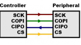
To comply with the latest OSHW design practices, we have adopted the new SPI signal nomenclature (SDO/SDI and PICO/POCI). The terms Master and Slave are now referred to as Controller and Peripheral. The MOSI signal on a controller has been replaced with SDO or PICO. Please refer to this announcement on the decision to deprecate the MOSI/MISO terminology and transition to the SDO/SDI naming convention.
The MAX3421E operates using a register set, accessed by an SPI interface at speeds up to 26MHz. Any SPI controller can add USB peripheral or host functionality using the simple 3- or 4- wire SPI interface The USB-timed operations are performed inside the MAX3421E with interrupts provided at completion, so any SPI controller does not need timers to meet USB timing requirements. Additionally, the firmware to operate the MAX3421E can also be simplified to only support a specific target device.
|

Default SPI bus connections on the USB Host Shield. |
Tip
To learn more about the serial peripheral interface (SPI) protocol, check out this great tutorial.
I/O Pins
In addition to the SPI pins, there are three I/O pins for the MAX3421E.
|

I/O pins on the USB Host Shield. |
-
INT- Interrupt (Output)The MAX3421E
INTpin outputs a signal when a USB event occurs, which requires the attention of the SPI controller. In level mode, theINTpin is open-drain and active low. In edge mode, the pin can be operated as push-pull output with programmable polarity. Users can enable the interrupt by setting the IE bit in the CPUCTL (R16) register. TheINTpin can also be configured to be triggered from the general-purpose inputs (GPIN0–GPIN7). -
GPX- General-Purpose Multiplexed (Output)The MAX3421E
GPXpin indicates one of five internal signals:OPERATE- The signal is high when the MAX3421E is able to operate after a power-up orRESreset.VBUS_DET- Provides theVBCOMPcomparator output.BUSACT- The signal is active (high), whenever there is traffic on the USB bus.INIRQ- In this mode,GPINinterrupts appear only on theGPXpin, and do not appear on theINToutput pin.- When the SEPIRQ bit of the MODE (R27) register is set high, the
BUSACTsignal is removed
- When the SEPIRQ bit of the MODE (R27) register is set high, the
SOF- A square wave is produced, with a positive edge that indicates the USB start-of-frame.
The internal MAX3421E signal that appears on
GPXis programmable by writing to theGPXBandGPXAbits of the PINCTL (R17) register and theSEPIRQbit of the MODE (R27) register.GPXB GPXA GPX PIN OUTPUT 0 0 OPERATE (Default State) 0 1 VBUS_DET 1 0 BUSACT/INIRQ 1 1 SOF -
RES- Device Reset (Input)Driving the
RESpin low causes a chip reset on the MAX3421E. In a chip reset, all registers are reset to their default states, except for PINCTL (R17), USBCTL (R15), and SPI logic. To bring the MAX3421E out of chip reset,RESmust be driven high.Note
The MAX3421E is internally reset if either VCC or VL is not present. The register file is not accessible under these conditions.
MAX3421E I/O Pins
The MAX3421E also includes eight general-purpose inputs (8) and outputs (8), that can be used to reclaim the I/O pins used for the SPI interface and gain additional ones.
GPOUT#- General-Purpose Push-Pull Outputs.GPIN#- General-Purpose Inputs.GPIN7–GPIN0are connected to VL with internal pullup resistors.

GPIO pins on the USB Host Shield.
USB-C Connector
Charging PD Devices
When a PD device is connected and the voltage output drops below 4.75V, the PD device will restrict its current draw to avoid potentially damaging the DFP (downward-facing port).
The USB-C connector is used to provide provided an interface to the MAX3421 USB controller, which can function as either a USB peripheral or host. It also supports limited power output at 5V. The available current is limited to what is supplied to the shield from either the VIN or 5V pin, up to the 750 mA threshold of the thermal fuse.
USB-C connector on the USB Host Shield.
Reset Button
Sometimes, an Arduino shield covers the Reset button of a user's Arduino board; therefore, a Reset button is provided on the USB-C Host shield. This allows users to easily reset their Arduino board without having to squeeze in between the Arduino board and shield to hit the button.

Reset button and RST pin on the USB Host Shield.
Note
The reset button (RST pin) is different from the RES (reset) pin for the MAX3421E.
- The button,
RSTpin on the shield, resets the microcontroller of the attached development board. - The
RESpin, connected to pin7on the shield, is a chip reset for the MAX3421E.
Jumper
There is a SHLD jumper on the top of the board that can be used to easily disconnect the shroud of the USB-C connector from GND.
New to jumper pads?
Check out our Jumper Pads and PCB Traces Tutorial for a quick introduction!
-

How to Work with Jumper Pads and PCB Traces

The SHLD jumper on the top of the USB Host Shield.