Single-Page View
Introduction
Attention
This guide is specific to the USB-C Host Shield board variant. For the variants with the USB (Type-A) connector, please refer to this guide by Hardware Fun.
-
SKU: DEV-21247

-
The SparkFun USB-C Host Shield has similar features to our previous USB Host Shield (v2), but we upgraded the USB Type-A connector to a USB-C connector. Additionally, the board provides users with the option to select either the
5VorVINpin to power the shield and USB port.The SparkFun USB Host Shield contains all of the digital logic and analog circuitry necessary to implement a USB peripheral/host controller with your Arduino board. This means you could use your Arduino microcontroller to interface with and control any USB 2.0 compatible device - flash drives, digital cameras, Bluetooth dongles, and much more!
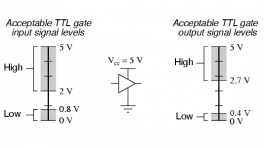
A four-wire serial interface is used to communicate with the host controller chip, so the shield connects the Arduino's hardware SPI pins (D10-13) to the MAX3421E. While the logic-level for the shield is 3.3V, all the SPI signals are sent through a hex converter to keep the shield compatible with any 5V Arduino boards.
Purchase from SparkFun
|
|
The SparkFun USB-C Host Shield has similar features to our previous USB Host Shield (v2), but we upgraded the USB Type-A connector to a USB-C connector. Additionally, the board provides users with the option to select either the The SparkFun USB Host Shield contains all of the digital logic and analog circuitry necessary to implement a USB peripheral/host controller with your Arduino board. This means you could use your Arduino microcontroller to interface with and control any USB 2.0 compatible device - flash drives, digital cameras, Bluetooth dongles, and much more! A four-wire serial interface is used to communicate with the host controller chip, so the shield connects the Arduino's hardware SPI pins (D10-13) to the MAX3421E. While the logic-level for the shield is 3.3V, all the SPI signals are sent through a hex converter to keep the shield compatible with any 5V Arduino boards. |

Required Materials
To get started with the USB-C Host Shield, users will need a few additional items. Users may already have some of these items, feel free to modify your cart accordingly. For users just getting started with electronics, we have linked a few tutorials to establish a foundation of knowledge to follow along with this hookup guide.
- Computer with an operating system (OS) that is compatible with all the software installation requirements.
-
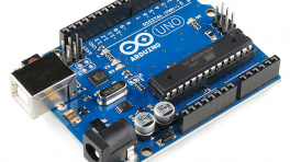
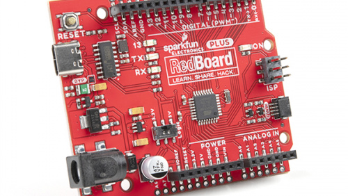
A compatible microcontroller/Arduino board; we recommend the SparkFun RedBoard Plus.
Warning
The recommended Arduino library for the USB Host Shield is not compatible with all microcontrollers or boards. For a complete list of compatible microcontrollers and boards, please refer to the
README.mdfile of USB Host Library Rev. 2.0. -
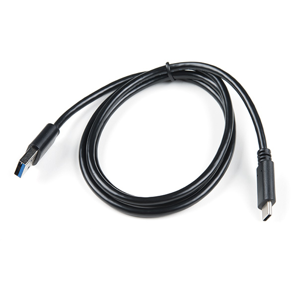
USB 3.1 Cable A to C - 3 Foot - Used to interface with the RedBoard Plus (1)
- If your computer doesn't have a USB-A slot or your microcontroller/Arduino board has a different USB connector, then choose an appropriate cable or adapter.
-
USB Peripheral Device (i.e. flash drive, game controller, smartphone, etc.) (1)
-
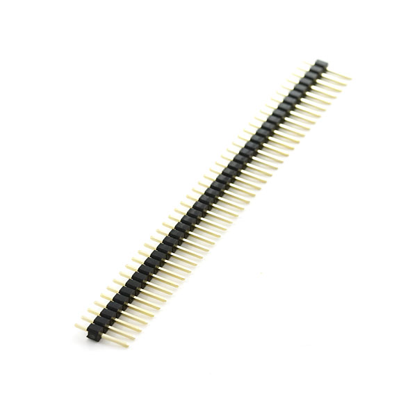
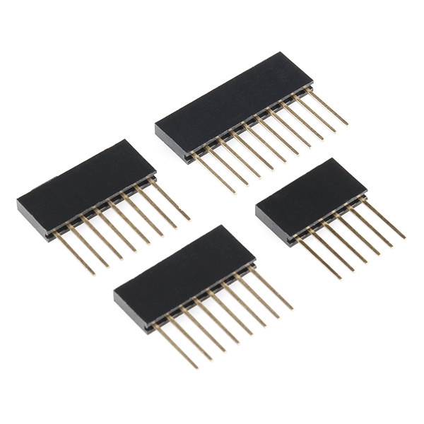
Headers - Used to connect the shield to the Arduino board (1)
- Check out some of the options for the Arduino R3/Uno form factor boards below; otherwise, click here for a full selection of our available headers.
-
Soldering Tools (1)
- Check out the beginner tool kit below; otherwise, click here for a full selection of our available soldering tools.
 USB 3.1 Cable A to C - 3 FootCAB-14743 |
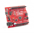
SparkFun RedBoard PlusDEV-18158 |
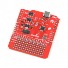
SparkFun USB-C Host ShieldDEV-21247 |
 Break Away Headers - StraightPRT-00116 |
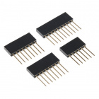
Arduino Stackable Header Kit - R3PRT-11417 |
|

SparkFun Beginner Tool KitTOL-14681 |


Tip
New to soldering? Check out our Through-Hole Soldering Tutorial for a quick introduction!

Arduino Examples
The following products are used in the Arduino examples shown in this hookup guide. Users are welcome to choose other products; however, these have been tested and verified to work with the examples.
 USB A (Female) to Type C (Male) ConverterCOM-21870 |
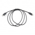 USB 2.0 Type-C Cable - 1 MeterCAB-16905 |
 SparkFun USB Thumb Drive (16GB)SWG-14658 |
 Bluetooth USB Module MiniWRL-09434 |
 8BitDo SN30 Pro Bluetooth GamepadWIG-17264 |

Jumper Modification
To modify the jumpers, users will need soldering equipment and/or a knife.
 Solder Lead Free - 100-gram SpoolTOL-09325 |

Weller WLC100 Soldering StationTOL-14228 |

Chip Quik No-Clean Flux Pen - 10mLTOL-14579 |

Hobby KnifeTOL-09200 |


Tip
New to jumper pads? Check out our Jumper Pads and PCB Traces Tutorial for a quick introduction!

Suggested Reading
As a more sophisticated product, we will skip over the more fundamental tutorials (i.e. Ohm's Law and What is Electricity?). However, below are a few tutorials that may help users familiarize themselves with various aspects of the board.
Hardware Overview
Board Dimensions
The board dimensions are illustrated in the drawing below; the listed measurements are in inches.

Board dimensions (PDF) for the USB Host Shield, in inches.
Need more measurements?
For more information about the board's dimensions, users can download the eagle files for the board. These files can be opened in Eagle and additional measurements can be made with the dimensions tool.
Download Eagle for Free!
Users can download Eagle for free from AutoDesk.
The program is free to use for hobbyists and students. However, it does require an account registration to utilize the software.
Dimensions Tool
This video from Autodesk demonstrates how to utilize the dimensions tool in Eagle, to include additional measurements:
Power
The MAX3421E USB controller only requires 3.3V to operate; however, the shield (and USB-C connector) is powered entirely through either the 5V or VIN pins of the connected Arduino board.

USB Host Shield power connections.
Below, is a general summary of the power circuitry on the board:
VIN- Provides a regulated 3.3V and 5V for the shield- To utilize this pin, users will need to connect an external power source to the barrel jack of the Arduino board they are using.
5V- Provides 5V and a regulated 3.3V for the shieldGND- The common ground or the 0V reference for the voltage supplies.-
VBUS- The voltage to the USB-C connector (5V)- In reference to the
VBUSnet of the schematic. - The available current is limited to what is supplied from the
VIN/5Vpin, up to the 750 mA threshold of the thermal fuse.
Info
When a PD device is connected and the voltage output drops below 4.75V, the PD device will restrict its current draw to avoid potentially damaging the DFP (downward-facing port).
- In reference to the
For more details, users can reference the schematic and the datasheets of the individual components in the power circuitry.
Power LED
The red, power (PWR) LED will light up once 5V is supplied to the shield. For most users, it will light up when power is supplied to the connected Arduino board.

USB Host Shield PWR status LED indicator.
Power Switches
There are two switches on the USB Host Shield. One provides a selectable power input for the shield (VIN or 5V) and the other provides power control (on/off) to the shield and USB connector.

Power switches on the USB Host Shield.
- Power Select
The power select switch allows users to easily choose the power supply for the shield. This switch mostly controls how the regulated 5V output for the USB-C connector is sourced. However, both options additionally supply the regulated 3.3V for the MAX3421E USB controller.- VIN - Draws power through the Arduino board's
VINpin- Provides a regulated 5V output to the USB-C connector from the
VINpin, which is separate/isolated from the5Vpin of the Arduino board - Provides a regulated 3.3V output for the MAX3421E USB controller from the regulated 5V output of the
VINpin
- Provides a regulated 5V output to the USB-C connector from the
- 5V - Draws power through the Arduino board's
5Vpin- Provides a 5V output to the USB-C connector from the
5Vpin of the Arduino board - Provides a regulated 3.3V output for the MAX3421E USB controller from the
5Vpin
- Provides a 5V output to the USB-C connector from the
- VIN - Draws power through the Arduino board's
- Main Power
The main power switch controls the power input to the shield. This switch turns the shield on or off; when off, the power output to the USB-C connector is also disabled.
USB-C Connector
Charging PD Devices
When a PD device is connected and the voltage output drops below 4.75V, the PD device will restrict its current draw to avoid potentially damaging the DFP (downward-facing port).
The USB-C port supports limited power output at 5V. The available current is limited to what is supplied to the shield from either the VIN or 5V pin, up to the 750 mA threshold of the thermal fuse.

USB-C connector on the USB Host Shield.
USB Controller
The MAX3421E from Maxim Integrated (now part of Analog Devices), is a USB peripheral/host controller that can be implemented as a full-speed USB peripheral or a full-/low-speed host compliant (USB specification rev 2.0). This allows for a vast collection of USB peripherals to be interfaced with an embedded system. The MAX3421E also includes eight general-purpose inputs and outputs so users can reclaim the I/O pins used for the SPI interface and gain additional ones.
Features
|
 MAX3421E chip on the USB-C Host Shield. |
I/O Pins
The MAX3421E is controlled with seven pins on the USB-C Host Shield. Additionally, the MAX3421E provides eight general-purpose inputs and outputs for users to reclaim their I/O pins and gain additional ones.
-

I/O pins used by the USB Host Shield. -
- SCK:
D13 - POCI:
D12 - PICO:
D11 - CS:
D10
- INT:
D9 - GPX:
D8 - RST:
D7
VIN5VGND
Info
For more information about the power pins, please refer to the power section (above).
- SCK:
New Feature
New on this shield, we have added a silkscreen indicator to mark the I/O pins used by the shield. This should help users who are stacking other shields to avoid pin conflicts without referencing the documentation.

SPI Pins
OSHW Compliance
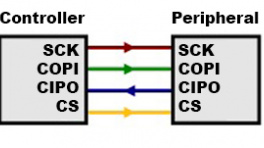
To comply with the latest OSHW design practices, we have adopted the new SPI signal nomenclature (SDO/SDI and PICO/POCI). The terms Master and Slave are now referred to as Controller and Peripheral. The MOSI signal on a controller has been replaced with SDO or PICO. Please refer to this announcement on the decision to deprecate the MOSI/MISO terminology and transition to the SDO/SDI naming convention.
The MAX3421E operates using a register set, accessed by an SPI interface at speeds up to 26MHz. Any SPI controller can add USB peripheral or host functionality using the simple 3- or 4- wire SPI interface The USB-timed operations are performed inside the MAX3421E with interrupts provided at completion, so any SPI controller does not need timers to meet USB timing requirements. Additionally, the firmware to operate the MAX3421E can also be simplified to only support a specific target device.
|

Default SPI bus connections on the USB Host Shield. |
Tip
To learn more about the serial peripheral interface (SPI) protocol, check out this great tutorial.
I/O Pins
In addition to the SPI pins, there are three I/O pins for the MAX3421E.
|

I/O pins on the USB Host Shield. |
-
INT- Interrupt (Output)The MAX3421E
INTpin outputs a signal when a USB event occurs, which requires the attention of the SPI controller. In level mode, theINTpin is open-drain and active low. In edge mode, the pin can be operated as push-pull output with programmable polarity. Users can enable the interrupt by setting the IE bit in the CPUCTL (R16) register. TheINTpin can also be configured to be triggered from the general-purpose inputs (GPIN0–GPIN7). -
GPX- General-Purpose Multiplexed (Output)The MAX3421E
GPXpin indicates one of five internal signals:OPERATE- The signal is high when the MAX3421E is able to operate after a power-up orRESreset.VBUS_DET- Provides theVBCOMPcomparator output.BUSACT- The signal is active (high), whenever there is traffic on the USB bus.INIRQ- In this mode,GPINinterrupts appear only on theGPXpin, and do not appear on theINToutput pin.- When the SEPIRQ bit of the MODE (R27) register is set high, the
BUSACTsignal is removed
- When the SEPIRQ bit of the MODE (R27) register is set high, the
SOF- A square wave is produced, with a positive edge that indicates the USB start-of-frame.
The internal MAX3421E signal that appears on
GPXis programmable by writing to theGPXBandGPXAbits of the PINCTL (R17) register and theSEPIRQbit of the MODE (R27) register.GPXB GPXA GPX PIN OUTPUT 0 0 OPERATE (Default State) 0 1 VBUS_DET 1 0 BUSACT/INIRQ 1 1 SOF -
RES- Device Reset (Input)Driving the
RESpin low causes a chip reset on the MAX3421E. In a chip reset, all registers are reset to their default states, except for PINCTL (R17), USBCTL (R15), and SPI logic. To bring the MAX3421E out of chip reset,RESmust be driven high.Note
The MAX3421E is internally reset if either VCC or VL is not present. The register file is not accessible under these conditions.
MAX3421E I/O Pins
The MAX3421E also includes eight general-purpose inputs (8) and outputs (8), that can be used to reclaim the I/O pins used for the SPI interface and gain additional ones.
GPOUT#- General-Purpose Push-Pull Outputs.GPIN#- General-Purpose Inputs.GPIN7–GPIN0are connected to VL with internal pullup resistors.

GPIO pins on the USB Host Shield.
USB-C Connector
Charging PD Devices
When a PD device is connected and the voltage output drops below 4.75V, the PD device will restrict its current draw to avoid potentially damaging the DFP (downward-facing port).
The USB-C connector is used to provide provided an interface to the MAX3421 USB controller, which can function as either a USB peripheral or host. It also supports limited power output at 5V. The available current is limited to what is supplied to the shield from either the VIN or 5V pin, up to the 750 mA threshold of the thermal fuse.
USB-C connector on the USB Host Shield.
Reset Button
Sometimes, an Arduino shield covers the Reset button of a user's Arduino board; therefore, a Reset button is provided on the USB-C Host shield. This allows users to easily reset their Arduino board without having to squeeze in between the Arduino board and shield to hit the button.

Reset button and RST pin on the USB Host Shield.
Note
The reset button (RST pin) is different from the RES (reset) pin for the MAX3421E.
- The button,
RSTpin on the shield, resets the microcontroller of the attached development board. - The
RESpin, connected to pin7on the shield, is a chip reset for the MAX3421E.
Jumper
There is a SHLD jumper on the top of the board that can be used to easily disconnect the shroud of the USB-C connector from GND.
Tip
Never modified a jumper before? Check out our Jumper Pads and PCB Traces tutorial for a quick introduction!

The SHLD jumper on the top of the USB Host Shield.
Hardware Assembly
Tip
Users unfamiliar with using Arduino shields should refer to the Arduino Shields (v2) tutorial first.
Headers
The pins for the USB Host Shield are broken out to 0.1"-spaced pins on the outer edges of the board. When selecting headers, be sure you are aware of the functionality you need.

Soldering headers to the USB Host Shield.
The Arduino Stackable Header Kit - R3 is a great option as it allows users to stack shields (w/ Uno/R3 footprint); with the pins still accessible through the female headers.

Stacking the USB Host Shield on the SparkFun RedBoard Plus.
Tip
If you have never soldered before or need a quick refresher, check out our How to Solder: Through-Hole Soldering guide.
USB Device
The USB port is utilized for the host/peripheral interface. Users only need to connect a USB device to the USB host shield or connect the shield to a computer with a USB-C cable.

The USB Host Shield with a USB-C adapter and flash drive attached. The shield sits on top of a RedBoard Plus connected to a computer.
Software Overview
Arduino IDE
Tip
For first-time users, who have never programmed before and are looking to use the Arduino IDE, we recommend beginning with the SparkFun Inventor's Kit (SIK), which includes a simple board like the Arduino Uno or SparkFun RedBoard and is designed to help users get started programming with the Arduino IDE.
Most users may already be familiar with the Arduino IDE and its use. However, for those of you who have never heard the name Arduino before, feel free to check out the Arduino website. To get started with using the Arduino IDE, check out our tutorials below:
What is an Arduino? |

Installing Arduino IDE |
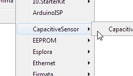
Installing an Arduino Library |
Installing Board Definitions in the Arduino IDE |
Need help setting up the RedBoard Plus?
RedBoard Plus
The following instructions should help users get started with the RedBoard Plus. For more information about the board, please check out our hookup guide below:
CH340 Driver
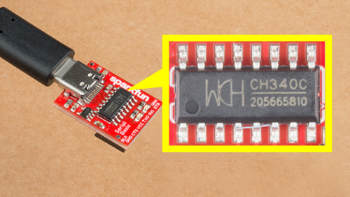
Users will need to install the appropriate driver for their computer to recognize the serial-to-UART chip on their board/adapter. Most of the latest operating systems will recognize the CH340C chip on the board and automatically install the required driver.
To manually install the CH340 driver on their computer, users can download it from the WCH website. For more information, check out our How to Install CH340 Drivers Tutorial.
Arduino IDE
When selecting a board to program in the Arduino IDE, users should select the Arduino Uno from the Tools drop-down menu (_i.e. Tools > Board > Arduino AVR Boards > Arduino Uno).

Arduino IDE 2.x.x - Alternative Method
In the newest version of the Arduino IDE 2.x.x, users can also select their board (green) and port (blue) from the Select Board & Port dropdown menu (yellow).

USB Host Library
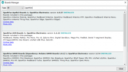
The USB Host Library Rev. 2.0 can be installed from the library manager in the Arduino IDE.

USB Host Library in the library manager of the Arduino IDE.
Info
For more details about the library, check out the online documentation.
Arduino IDE (v1.x.x)
In the Arduino IDE v1.x.x, the library manager will have the following appearance for the USB Host Shield library:

Alternative Libraries
Users are welcome to try other libraries for the MAX3421E, such as the ones listed below. However, our technical support team will only provide assistance with the USB Host Library Rev. 2.0 recommended in this hookup guide.
Supported Boards
For a detailed and up-to-date list of boards supported by this library, check out the README.md of the GitHub repository:
- All official Arduino AVR boards (Uno, Duemilanove, Mega, Mega 2560, Mega ADK, Leonardo etc.)
- Arduino Due
- Teensy (Teensy++ 1.0, Teensy 2.0, Teensy++ 2.0, Teensy 3.x, Teensy LC and Teensy 4.x)
- For the Teensy 3.x, install this SPI library and add
#include <spi4teensy3.h>to the*.inosketch file.
- For the Teensy 3.x, install this SPI library and add
- STM32F4
- Take a look at the following example code.
- ESP8266 is supported using the ESP8266 Arduino core
- Uses pins
15and5forCSandINT, respectively. GPIO6-GPIO11andGPIO16are NOT usable.
- Uses pins
- ESP32 is supported using the arduino-esp32
GPIO5:CSGPIO17:INTGPIO18:SCKGPIO19:POCIGPIO23:PICO
I/O Pin Modifications
The SPI pins used by this library are dictated by SPI library for the Arduino core being utilized and cannot be changed easily. It is recommended that the default pins of the SPI library be utilized.
However, the USB Host Library also declares its CS and INT pins. These pins can be reconfigured in the library by modifying the UsbCore.h file:
For instance, if a user wanted to reconfigure the CS pin to D7 and the INT pin to D2 of the RedBoard Plus (or any other Arduino Uno/ATmega328P based board), line 58 should read:
Tip
The information above is an example of a pin modification. However, it is not required for the general use of the shield and the examples in this guide. For more information, please refer to the instructions in the README.md of the GitHub repository.
Other Boards
For other boards, users will need to modify the lines based on the microcontroller type. For example, with the SparkFun IoT RedBoard users would need to modify line 52.
Arduino Examples
USB Description
For our first example, we will be utilizing the USB_dec example from the USB_Host_Shield_2.0 Arduino library. This example can be found in the File dropdown menu (i.e. (1) File > Examples > USB Host Shield Library 2.0 > USB_Desc). Once the example has been opened, users should see two files USB_desc.ino and pgmstrings.h.

Select the USB_Descexample sketch from theFiledrop-down menu.
Example Files
1 2 3 4 5 6 7 8 9 10 11 12 13 14 15 16 17 18 19 20 21 22 23 24 25 26 27 28 29 30 31 32 33 34 35 36 37 38 39 40 41 42 43 44 45 46 47 48 49 50 51 52 53 54 55 56 57 58 59 60 61 62 63 64 65 66 67 68 69 70 71 72 73 74 75 76 77 78 79 80 81 82 83 84 85 86 87 88 89 90 91 92 93 94 95 96 97 98 99 100 101 102 103 104 105 106 107 108 109 110 111 112 113 114 115 116 117 118 119 120 121 122 123 124 125 126 127 128 129 130 131 132 133 134 135 136 137 138 139 140 141 142 143 144 145 146 147 148 149 150 151 152 153 154 155 156 157 158 159 160 161 162 163 164 165 166 167 168 169 170 171 172 173 174 175 176 177 178 179 180 181 182 183 184 185 186 187 188 189 190 191 192 193 194 195 196 197 198 199 200 201 202 203 204 205 206 207 208 209 210 211 212 213 214 215 216 217 218 219 220 221 222 223 224 225 226 227 228 229 230 231 232 233 234 235 236 237 238 239 240 241 242 243 244 245 246 247 248 249 250 251 252 253 254 255 256 257 258 259 260 261 262 263 264 265 266 267 268 269 270 271 272 273 274 275 276 277 278 279 280 281 282 283 284 285 286 287 288 289 290 291 292 293 294 295 296 297 298 299 300 301 302 303 304 305 306 307 308 309 310 311 312 313 314 315 316 317 318 319 320 321 322 323 324 325 326 327 328 329 330 331 332 333 334 335 336 337 338 339 340 341 342 343 344 345 346 | |
Users will need to connect a peripheral USB device to the USB-C connector, before running the example. After the example begins, users should see an output in the Serial Monitor with a description of the connected USB device.
The USB Host Shield with a USB-C adapter and flash drive attached.
USB Hubs
If users connect USB hubs or USB cables with a hub to the USB host shield, utilize the hub_demo example from the USB_Host_Shield_2.0 Arduino library instead. This example can be found in the File dropdown menu (i.e. File > Examples > USB Host Shield Library 2.0 > hub_demo) and will list the USB description for the hub(s) and all the peripheral devices connected to the hub(s).
Only interested in the USB hub description?
To see just the USB description for the hub(s) connected to the USB host shield, follow the information in the library's FAQ. Utilizing the USB_dec example, uncomment lines 12-18(1).
- Each instance of
USBHub Hub<number>(&Usb);enables a USB hub, but the library is limited up to seven USB hubs.
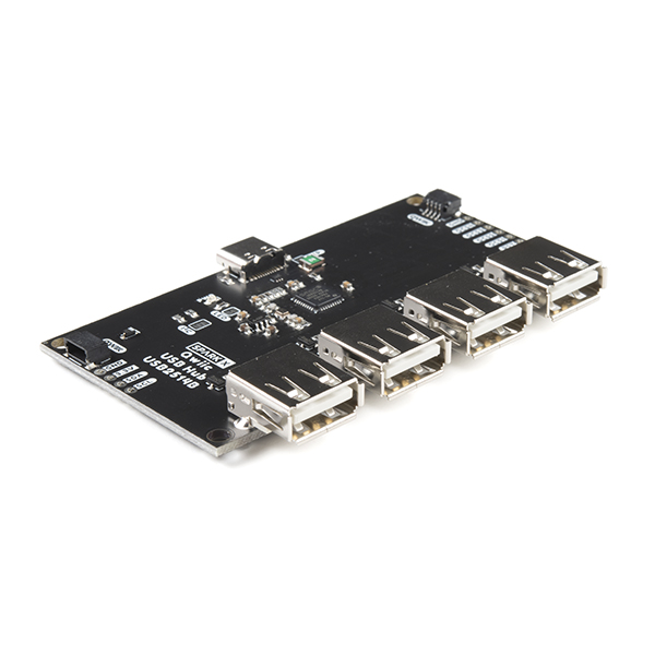
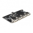 Qwiic USB Hub - USB2514BSPX-18014 |
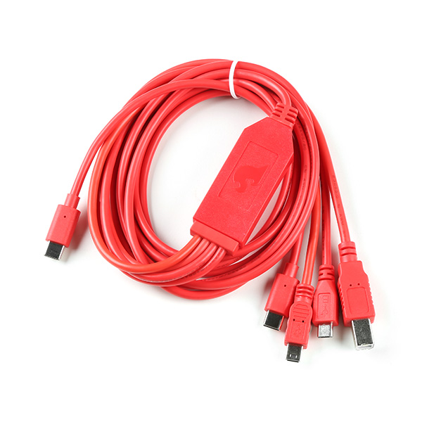
SparkFun 4-in-1 Multi-USB Cable - USB-C HostCAB-21271 |
SparkFun 4-in-1 Multi-USB Cable - USB-A HostCAB-21272 |

HID Keyboard and Mouse
In this example, we will be utilizing the USBHIDBootKbdAndMouse example from the USB_Host_Shield_2.0 Arduino library. This example can be found in the File dropdown menu (i.e. (1) File > Examples > USB Host Shield Library 2.0 > HID > USBHIDBootKbdAndMouse). Once the example has been opened, users should see the USBHIDBootKbdAndMouse.ino example sketch.

Select the USBHIDBootKbdAndMouseexample sketch from theFiledrop-down menu.
USBHIDBootKbdAndMouse.ino
1 2 3 4 5 6 7 8 9 10 11 12 13 14 15 16 17 18 19 20 21 22 23 24 25 26 27 28 29 30 31 32 33 34 35 36 37 38 39 40 41 42 43 44 45 46 47 48 49 50 51 52 53 54 55 56 57 58 59 60 61 62 63 64 65 66 67 68 69 70 71 72 73 74 75 76 77 78 79 80 81 82 83 84 85 86 87 88 89 90 91 92 93 94 95 96 97 98 99 100 101 102 103 104 105 106 107 108 109 110 111 112 113 114 115 116 117 118 119 120 121 122 123 124 125 126 127 128 129 130 131 132 133 134 135 136 137 138 139 140 141 142 143 144 145 146 147 148 149 150 151 152 153 154 155 156 157 158 159 160 161 162 163 164 165 166 167 168 169 170 171 172 173 | |
Users will need to connect an HID device (keyboard and/or mouse) to the USB-C host shield with a USB cable, before running the example. After the example begins, users should see an output in the Serial Monitor with print out based on the user's interaction with their HID device.
HID Game Controller
In these examples, we will be connecting the 8BitDo SN30 Pro to the USB-C host shield. Users will need the following items for the examples below:
-
8BitDo SN30 Pro Bluetooth Gamepad
For instructions on how to use the 8BitDo SN30 Pro, please refer to their user manual. - USB 2.0 Type-C Cable - 1 Meter
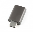
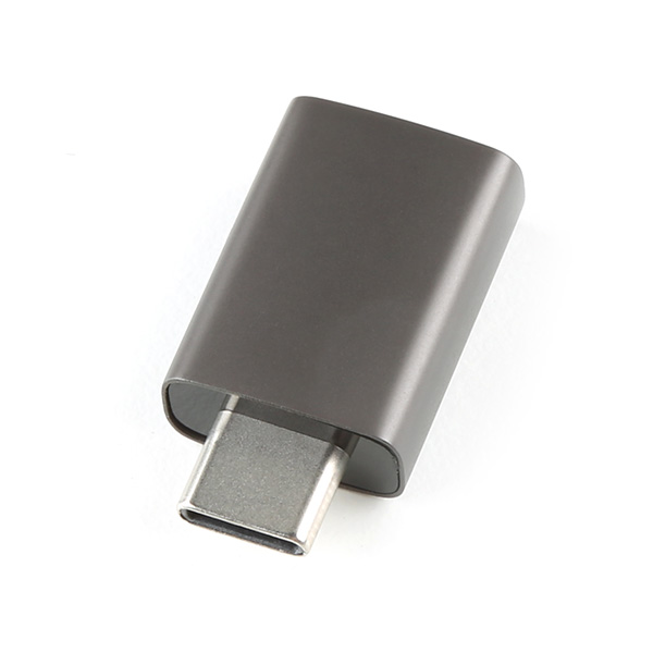
- USB A (Female) to Type C (Male) Converter
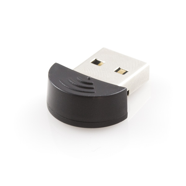
- Bluetooth USB Module Mini
-
8BitDo SN30 Pro Bluetooth Gamepad
WIG-17264
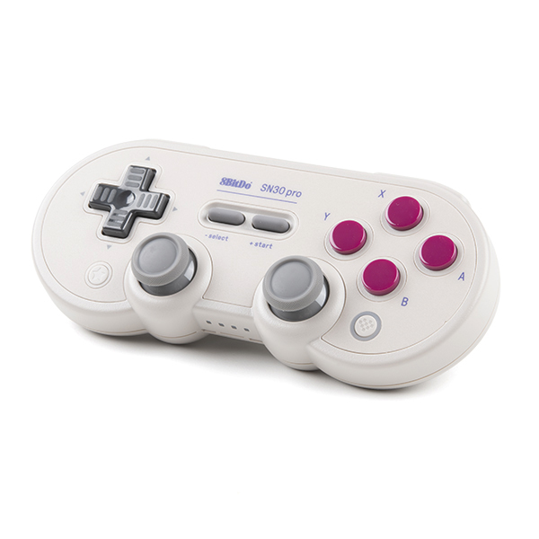
8BitDo SN30 Pro Manual
For instructions on how to use the 8BitDo SN30 Pro, please refer to their user manual.
-
USB 2.0 Type-C Cable - 1 Meter
CAB-16905
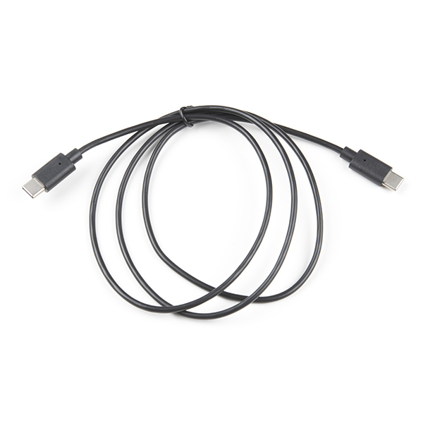
(Coming Soon) -
USB A (Female) to Type C (Male) Converter
COM-21870
-
Bluetooth USB Module Mini
WRL-09434
USB Connection
In this example, we will be utilizing the XBOXUSB example from the USB_Host_Shield_2.0 Arduino library. This example can be found in the File dropdown menu (i.e. (1) File > Examples > USB Host Shield Library 2.0 > Xbox > XBOXUSB). Once the example has been opened, users should see the XBOXUSB.ino example sketch.

Select the XBOXUSBexample sketch from theFiledrop-down menu.
XBOXONE.ino
1 2 3 4 5 6 7 8 9 10 11 12 13 14 15 16 17 18 19 20 21 22 23 24 25 26 27 28 29 30 31 32 33 34 35 36 37 38 39 40 41 42 43 44 45 46 47 48 49 50 51 52 53 54 55 56 57 58 59 60 61 62 63 64 65 66 67 68 69 70 71 72 73 74 75 76 77 78 79 80 81 82 83 84 85 86 87 88 89 90 91 92 93 94 95 96 97 98 99 100 101 102 103 104 105 106 107 108 109 110 111 112 113 | |
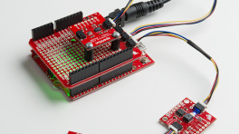
Users will need to turn on and connect the controller to the USB-C host shield with a USB cable, before running the example.

8BitDo controller connected to the USB-C Host Shield with a USB-C cable.
Note
To turn on the controller, press the Start+X buttons. Users should see two status LEDs blinking at the bottom of the controller.
After the example begins, users should see an output in the Serial Monitor with print out based on the user's interaction with their controller.
Bluetooth Connection
In this example, we will be utilizing the XBOXONESBT example from the USB_Host_Shield_2.0 Arduino library. This example can be found in the File dropdown menu (i.e. (1) File > Examples > USB Host Shield Library 2.0 > Xbox > XBOXONESBT). Once the example has been opened, users should see the XBOXONESBT.ino example sketch.
-
Select the XBOXONESBTexample sketch from theFiledrop-down menu.
XBOXONESBT.ino
1 2 3 4 5 6 7 8 9 10 11 12 13 14 15 16 17 18 19 20 21 22 23 24 25 26 27 28 29 30 31 32 33 34 35 36 37 38 39 40 41 42 43 44 45 46 47 48 49 50 51 52 53 54 55 56 57 58 59 60 61 62 63 64 65 66 67 68 69 70 71 72 73 74 75 76 77 78 79 80 81 82 83 84 85 86 87 88 89 90 91 92 93 94 95 96 97 98 99 100 101 102 103 104 105 106 107 108 109 110 111 112 113 114 115 116 117 118 119 120 121 122 123 124 125 126 127 128 129 130 131 132 133 | |
Users will need to connect the Bluetooth USB module to the USB-C host shield with the USB adapter before running the example. After the example begins, users should see an output in the Serial Monitor with print out based on the user's interaction with their controller.

Bluetooth module connected to the USB-C Host Shield; and paired with an 8BitDo controller.
!! note Make sure to wait until after the board restarts and executes the example, before pairing the 8BitDo controller with the Bluetooth module.
Bluetooth Pairing the Controller
To turn on the controller, press the Start+X buttons. Users should see two status LEDs blinking at the bottom of the controller. To pair the controller, press and hold the pair button at the top of the controller, next to the USB-C connector, for 3 seconds. Once paired, the controller should vibrate.
Troubleshooting Tips
Need Help?
If you need technical assistance or more information on a product that is not working as you expected, we recommend heading on over to the SparkFun Technical Assistance page for some initial troubleshooting.
If you can't find what you need there, the SparkFun Forums is a great place to search for additional information and to ask questions.
Account Registration Required
If this is your first visit to our forum, you'll need to register an account to post questions.
Initialization Failure
The following error message, in the serial terminal, indicates that there was a problem communicating with the MAX3421E chip.
This error occurs here in the example code:
Here are a few steps users can perform to diagnose the issue:
- Double-check the hardware connections; including, but not limited to the solder joints, header pins (male and female), etc.
- Disconnect power from the board and try a continuity test with a multimeter.
- Make sure the switches are in the correct position to provide power to the shield.
- The shield requires a minimum 5V input voltage.
- The red, power LED should be lit when the shield is powered.
- Double-check the library for any I/O pin modifications.
USB Hub
If users connect USB hubs or USB cables with a hub to the USB host shield, refer to the hub_demo example from the USB_Host_Shield_2.0 Arduino library. This example can be found in the File dropdown menu (i.e. File > Examples > USB Host Shield Library 2.0 > hub_demo) and will list the USB description for the hub(s) and all the peripheral devices connected to the hub(s).
Only interested in the USB hub description?
To see just the USB description for the hub(s) connected to the USB host shield, follow the information in the library's FAQ. Utilizing the USB_dec example, uncomment lines 12-18(1).
- Each instance of
USBHub Hub<number>(&Usb);enables a USB hub, but the library is limited up to seven USB hubs.
Resources:
Product Resources
- Product Page
- Schematic (PDF)
- Eagle Files (ZIP)
- Board Dimensions (PDF)
- Arduino Library: USB Host Rev. 2.0
- GitHub Hardware Repo
Additional Resources
Hardware Component Documentation
- USB Peripheral/Host Controller: MAX3421E (PDF)
- Errata_MAX3421E (PDF)
- Programming Guide (PDF)
- Technical Articles
- Application Notes
- Power Regulation:
- Logic-Level Converter:
- 74HC4050 (PDF)
Manufacturer's Resources
Maxim Integrated (now part of Analog Devices) also provides great resources for the MAX3421E USB Peripheral/Host Controller: