Hardware Overview
Introduction
Welcome to the SparkFun Experiential Robotics Platform (XRP) Controller Hardware Overview. This document provides detailed overviews of the hardware present on both versions of the XRP Controller; the XRP Controller and XRP Controller - Beta.
Each version of the XRP Controller has their own hardware overview section linked in the navigation menu to the left. If you're not sure which version to select, click on the image below matching the XRP Controller you have:
 |
 |
| SparkFun Experiential Robotics Platform (XRP) Controller | SparkFun Experiential Robotics Platform (XRP) Controller - Beta |
|---|
XRP Controller
In this document, we'll take a close look at the heart of the Experiential Robotics Platform (XRP) Kit, the XRP Controller. This document outlines all of the parts on this board you'll interact with while building and using the XRP Kit.
Controller Board Overview
Let's take a broad look at the major components on the XRP Controller. The photo below points them out along with their names:

You'll notice that along with the arrows showing the name of some of the smaller components, the board uses what's called silkscreen to label all the connectors, buttons, LEDs and other parts you'll interact with while building and using the XRP Robotics Kit.
Raspberry Pi RP2350 & Radio Module 2
The Raspberry Pi RP2350 acts as the brain of this board. The RP2350 communicates with the motor controllers, IMU and other components to control the robotics kit's behavior. The Raspberry Pi Radio Module 2 (RM2) adds wireless connectivity to the XRP Controller over both WiFi and Bluetooth®. The photo below highlights the RP2350 and RM2 on the Controller Board:

Think of the RP2350 as a brain sending signals to other parts of the "body" to tell them what to do. It has several General Purpose Input/Output (GPIO) pins that connect to the other major parts on this board so it can send and receive data from them and return it to you visually (such as seeing the motors move) or virtually (such as watching data on a computer monitor).
The Radio Module 2 connects to both WiFi networks and Bluetooth devices allowing wireless connectivity for the XRP Kit. It communicates with the RP2350 over its serial peripheral interface (SPI) and also has a few general purpose inputs and outputs (GPIO) that are connected to the two 2x20 expansion headers on the XRP Controller Board.
DRV8411A Motor Drivers
The pair of DRV8411A H-Bridge motor drivers from Texas Instruments™ on the XRP Controller Board control the direction and speed of the XRP Kit's motors.

The term H-bridge comes from how this circuit design looks on a schematic diagram. It has four internal switches that control whether the motor spins Clockwise (CW), Counter Clockwise (CCW), Coasts (no drive power), and Stops. When going through the XRP Kit curriculum you'll learn how to program the robot to tell the motor drivers to control the motors' speed and direction.
LSM6DSO 6-Dof IMU
The LSM6DSO 6-DoF (Degrees of Freedom) IMU (Inertial Measurement Unit) from STMicroelectronics™ combines an accelerometer and gyroscope into a single IC (integrated circuit). This sensor lets you measure the robot's acceleration in three dimensions and also measure the orientation and angle of the robot.

The accelerometer in this chip has four measurement ranges of ±2/±4/±8/±16 g. These ranges allow you to customize the limits of the acceleration forces measured. The gyroscope has five selectable measurement ranges of ±125/±250/±500/±1000/±2000 DPS (degrees per second). Refer to the silk screen symbols on the XRP Controller for the directions of each axis.
Power Components
Now let's take a closer look at the parts on this board used for providing power to it.

Barrel Jack Connector
The barrel jack connector is the primary power input for the entire XRP Kit. This connector mates with the cable from the XRP Kit's battery pack for battery-powered operation. Take note that the maximum safe voltage that can be applied to this connector is 11V and the minimum to run the system is 5V. The 4-AA battery pack included with the kit supplies a maximum of 6V so most users will have no issues exceeding the max voltage.
USB-C Connector
The USB-C connector provides power to the XRP Controller Board with 5V from a USB cable. It also is the primary interface you'll use to initially set up the XRP Controller Board with a computer and program the RP2350 using a USB-C cable.
Power Switch
The power switch highlighted above controls the voltage input to the Controller Board. This two-way switch turns the kit's power on and off. You can use this to turn the robot off while keeping the battery pack plugged in. The switch does not affect the RP2350's power when a USB cable is plugged in.
Motor Connectors
The Controller Board has four six-pin connectors labeled Motor L, Motor R, Motor 3 and Motor 4 and four three-pin connectors labeled Servo 1, Servo 2, Servo 3 and Servo 4.

DC Motor Connectors
The DC Motor connectors are where you'll plug in the left and right motors while assembling the kit. These connectors include the power connections for the motor as well as the encoders on the motors. The board routes these connections through the motor drivers to GPIO pins on the RP2350. You'll use these pins to monitor how many rotations the motor completes and use that data to determine how far the robot has traveled. Refer to the Pinout table at the end of this document for the specific GPIO pins each motor connects to on the RP2350. The Controller Board has two extra motor connectors for expansion projects using more than two motors.
Servo Motor Connectors
The four three-pin connectors on either side of the board labeled Servo 1, Servo 2, Servo 3 and Servo 4 mate with servo motors. You'll use the Servo 2 connector to hook up the servo included in the XRP kit. The other three connectors are extra for expansion projects. These connectors have power pins (5V and Ground) and a signal pin to control the motion of the servo motor. Servo motors use a communication method called pulse width modulation (PWM) that tells the motor to move and with some motors, where to move to. If you're interested in learning more about how servo motors work, you may want to check out SparkFun's Servos Explained page for information and tutorials on how to use them.
Sensor & Qwiic Connectors
The Controller Board has four four-pin connectors labeled (from left to right when looking at the labels upright) Line, Qwiic 1, Qwiic 0 and DIST. Their labels indicate their use as well as which GPIO pins they connect to on the RP2350. These connectors provide an easy plug-in connection for the line follower and distance sensor as well as two extra connectors for expansion projects. These connectors are polarized meaning they only work when connected properly but they are keyed and there is only one way to plug a cable into them.

Line Follower Connector
The Line connector is where you'll plug the cable for the line follower sensor into. This connects the sensor's two signal lines, Left and Right, to the RP2350's GPIO44 (Left) and GPIO45 (Right) pins. You'll use these pins to monitor whenever the sensor detects the robot has gone past the left or right threshold when performing line-following experiments. When connecting the Qwiic adapter cable that plugs into this connector, make the following connections to the Line Follower Sensor:
- Red - 3.3V
- Blue - S1
- Yellow - S2
- Black - GND
Distance Sensor Connector
The Dist connector is where you'll plug the cable for the ultrasonic range sensor into. It connects the distance sensor's Echo and Trigger lines to the RP2350's GPIO0 (Trigger) and GPIO1 (Echo). You'll use these pins to receive distance data from the ultrasonic range sensor. When connecting the Qwiic adapter cable that plugs into this connector, make the following connections to the Distance Sensor:
- Red - VCC
- Blue - Trig
- Yellow - Echo
- Black - GND
Qwiic Connectors
The Qwiic connectors work with SparkFun's Qwiic ecosystem of sensors that communicate over I2C. This is a two-wire communication protocol that works with a large variety of sensors and other electronics. With this, you can customize the XRP Kit to add things like environmental sensing, OLED screens, data logging, and more!
Buttons
The Controller Board has three push buttons labeled USER, RESET and BOOT (on the RP2350).

The USER button connects to GPIO36 on the RP2350 which allows it to be programmed for various purposes. The RESET button does just what its name suggests and resets the entire board when pressed. This can help to reboot the robot or to restart a sequence you want the Robotics Kit to perform. Holding the BOOT button either when plugging in a USB cable or when pressing the RESET button sets the RP2350 to behave as a mass storage device when connected to a computer for uploading firmware.
LEDs
There are five LEDs on the XRP Controller Board labeled MOT, SYS, LOW VOLT, STAT and RGB.

These LEDs are there to provide a visual indication to users. The LEDs labeled MOT and SYS turn on when their respective power rails are powered. The MOT LED turns on when the motors have power available. The SYS LED turns on when the 3.3V/System circuit is powered. This circuit powers the RP2350, RM2, sensors, and the expansion connectors. The LOW VOLT LED connects to the 5V Buck regulator POWER_GOOD pin. It provides a quick visual indicator to notify users that the supply voltage has dropped below the operating threshold and the board is underpowered. This is not technically a low battery indicator but it coincidentally starts illuminating when 4xAA batterys are low, depending on the battery chemistry.
The other two LEDs labeled STAT and RGB are user-programmable status LEDs you can program for whatever behavior you prefer. The STAT LED connects to GPIO0 on the Radio Module and can be useful to indicate behavior from the radio such as connection status or data transmission. The RGB LED connects to GPIO37 on the RP2350 and can be programmed to change to any color based on whatever behavior you'd like. For example, you can have it turn from Green to Red when the distance sensor detects the robot is nearing an obstacle.
Expansion Headers
The XRP Controller Board now features a pair of 2x20 female headers that connect to nearly all the RP2350's and RM2's available pins to allow for more customization options for the XRP platform. Many of these pins are shared between the connectors and other components on the XRP Control Board so take care to ensure they are not being used by any peripherals (motors, sensors, etc.) before connecting and programming them for a different functionality.

The inner rows of this expansion header nearly matches the pinout of the Pico W 2 (minus the analog-to-digital conversion pins) and can be used with peripheral boards that work with the Pico 2 W. Please note this is NOT a socket for a Pico 2 W. The outer row contains available GPIO pins from the RM2, extra GPIO pins from the RP2350 along with voltage pins. The image below and following table offers a quick reference for the pinout and labels on the expansion headers as well as any other connectors (motors, sensors, etc.) or peripheral (button, LED, etc.) shared between them.


Solder Jumpers
Warning
These solder jumpers can change the behavior of the board in a lasting way. Using these requires extra tools not included in the XRP Kit along with knowledge of how to use and interact with solder jumpers. We recommend that only advanced users adjust and change the solder jumpers. If you'd like to learn more about how to use solder jumpers, check out SparkFun's How to Work with Jumper Pads and PCB Traces tutorial.
The XRP Controller Board has fourteen solder jumpers. A solder jumper provides a customization option for advanced users to control the behavior of the pins and components they connect to. The solder jumpers on this board are labeled (from top-to-bottom reading left-to-right when looking at the photo below): I2C0, I2C1, M-L/3 REF, M-L CUR, M-R CUR, M-3 CUR, M-4 CUR, M-R/4 REF ADR, VIN MEAS, BYPM, SHLD, PWR MOT and PWR SYS.

| Label | Default State | Function | Notes |
|---|---|---|---|
| I2C0 | CLOSED | Pulls SDA/SCL on I2C 0 to 3.3V through two 2.2kΩ resistors. | Open completely to disable the pull up resistors on the I2C 0 bus. |
| I2C1 | CLOSED | Pulls SDA/SCL on I2C 0 to 3.3V through two 2.2kΩ resistors. | Open completely to disable the pull up resistors on the I2C 1 bus. |
| M-L/3 REF | CLOSED | Sets the Left/3 DRV8411 motor driver's voltage reference to 3.3V | Sets the DRV8411's reference voltage to match the system voltage. Open to set to a different voltage. |
| M-L CUR | CLOSED | Connects the Left Motor current sense output to IO40. | Lets users measure motor current draw using the ADC on IO40. Open to free up IO40 for other use. |
| M-R CUR | CLOSED | Connects the Right Motor current sense output to IO43. | Lets users measure motor current draw using the ADC on IO43. Open to free up IO43 for other use. |
| M-3 CUR | CLOSED | Connects the Motor Three current senss output to IO41. | Lets users measure motor current draw using the ADC on IO41. Open to free up IO41 for other use. |
| M-4 CUR | CLOSED | Connects the Motor Four current sense output to IO42. | Lets users measure motor current draw using the ADC on IO42. Open to free up IO42 for other use. |
| M-R/4 REF | CLOSED | Sets the Right/4 DRV8411 motor driver's voltage reference to 3.3V | This sets the DRV8411's reference voltage to match the system voltage. Open to set to a different voltage. |
| ADR | CLOSED | Sets the LSM6DSO's I2C address to 0x6B. | Open to switch the I2C address to 0x6A. |
| VIN MEAS | CLOSED | Connects the VIN measurement circuit to IO46 | Open to free up IO46 for alternate use |
| BYP | OPEN | Enables the fuse for the barrel jack input. | Close to bypass the fuse for the barrel jack. |
| SHLD | CLOSED | Connects the USB-C shield pin to the board's ground plane. | Open to isolate the USB-C shield pin |
| PWR MOT | CLOSED | Completes the Motor Power LED circuit. | Open to disable the Motor Power LED. |
| PWR SYS | CLOSED | Completes the System Power LED circuit. | Open to disable the System Power LED. |
Pinout Reference Table
The table below gives a quick reference for the complete pinout of the XRP Controller and which pins they connect to on the RP2350.
| RP2350 GPIO Pin | Connector/Peripheral Label | Expansion Header Pin Label | Pin Function |
|---|---|---|---|
| GPIO0 | DIST | 0 | Distance Trigger Pin |
| GPIO1 | DIST | 1 | Distance Echo Pin |
| GPIO2 | Motor 4 | IO2 | Motor 4 Encoder A |
| GPIO3 | Motor 4 | IO3 | Motor 4 Encoder B |
| GPIO4 | Qwiic 0 | IO4 | I2C 0 Data Signal |
| GPIO5 | Qwiic 0 | IO5 | I2C 0 Clock |
| GPIO6 | Servo 1 | IO6 | Servo 1 Signal |
| GPIO7 | Servo 3 | IO7 | Servo 3 Signal |
| GPIO8 | Servo 4 | IO8 | Servo 4 Signal |
| GPIO9 | Servo 2 | IO9 | Servo 2 Signal |
| GPIO10 | Motor 4 | IO10 | Motor 4 Phase Pin |
| GPIO11 | Motor 4 | IO11 | Motor 4 Enable Pin |
| GPIO12 | None | IO12 | Available I/O |
| GPIO13 | None | IO13 | Available I/O |
| GPIO14 | None | IO14 | Available I/O |
| GPIO15 | None | IO15 | Available I/O |
| GPIO16 | None | IO16 | Available I/O |
| GPIO17 | None | IO17 | Available I/O |
| GPIO18 | None | IO18 | Available I/O |
| GPIO19 | None | IO19 | Available I/O |
| GPIO20 | Motor 3 | IO20 | Motor 3 Phase Pin |
| GPIO21 | Motor 3 | IO21 | Motor 3 Enable Pin |
| GPIO22 | Motor 3 | IO22 | Motor 3 Encoder A Pin |
| GPIO23 | Motor 3 | IO23 | Motor 3 Encoder B Pin |
| GPIO24 | Motor R | IO24 | Motor R Encoder A Pin |
| GPIO25 | Motor R | IO25 | Motor R Encoder B Pin |
| GPIO26 | None | None | RM2 Power On | GPIO27 | None | None | RM2 Chip Select | GPIO28 | None | None | RM2 SPI Clock | GPIO29 | None | None | RM2 SPI Data |
| GPIO30 | Motor L | IO30 | Motor L Encoder A Pin |
| GPIO31 | Motor L | IO31 | Motor L Encoder B Pin |
| GPIO32 | Motor R | IO32 | Motor R Phase Pin |
| GPIO33 | Motor R | IO33 | Motor R Enable Pin |
| GPIO34 | Motor L | IO34 | Motor L Phase Pin |
| GPIO35 | Motor L | IO35 | Motor L Enable Pin |
| GPIO36 | User Button | 36 | User button input |
| GPIO37 | RGB | RGB | WS2812 Data In Pin |
| GPIO38 | Qwiic 1 | SDA1 | I2C 1 Data |
| GPIO39 | Qwiic 1 | SCL1 | I2C 1 Clock |
| GPIO40 | None | IO40 | Motor Left Current Measure |
| GPIO41 | None | IO41 | Motor 3 Current Measure |
| GPIO42 | None | IO42 | Motor 4 Current Measure |
| GPIO43 | None | IO43 | Motor Right Current Measure |
| GPIO44 | Line | IO44 | Line Follower Left Signal |
| GPIO45 | Line | IO45 | Line Follower Right Signal |
| GPIO46 | None | IO46 | Voltage Input Measure |
| GPIO47 | None | None | PSRAM Chip Select |
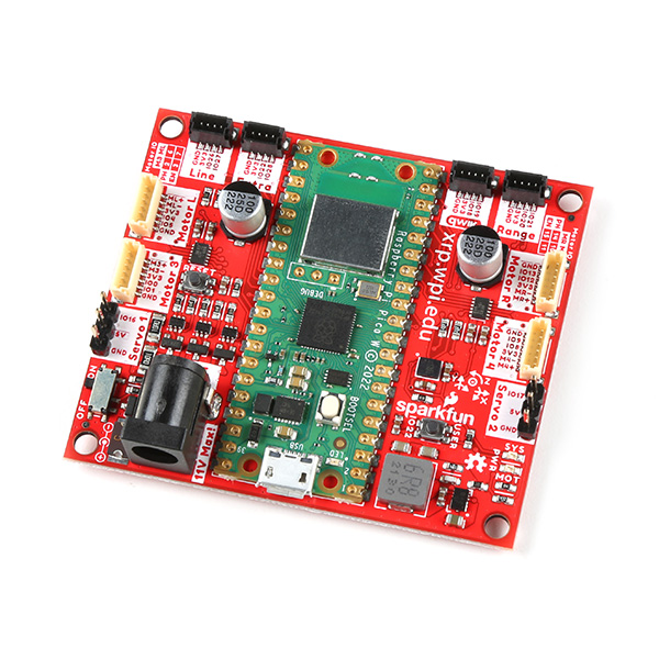
XRP Controller - Beta
In this document, we'll take a close look at the heart of the Experiential Robotics Platform (XRP) Kit - Beta, the XRP Controller - Beta. This document outlines all of the parts on this board you'll interact with while building and using the XRP Kit - Beta.
XRP Controller - Beta Overview
Let's take a broad look at the major components on the XRP Controller - Beta. The photo below points them out along with their names:

You'll notice that along with the arrows showing the name of some of the smaller components, the board uses what's called silkscreen to label all the connectors, buttons, LEDs and other parts you'll interact with while building and using the XRP Kit - Beta.
Raspberry Pi Pico W
The Raspberry Pi Pico W microcontroller acts as the brain of this board. It combines a RP2040 processor with a wireless module for both 2.4GHz 802.11n wireless LAN and Bluetooth™ 5.2. The RP2040 communicates with the motor controllers, IMU and other components to control the robotics kit's behavior. The photo below highlights the Pico W on the Controller board:

Think of the Pico W as a brain sending signals to other parts of the "body" to tell them what to do. It has several General Purpose Input/Output (GPIO) pins that connect to the other major parts on this board so it can send and receive data from them and return it to you visually (such as seeing the motors move) or virtually (such as watching data on a computer monitor).
DRV8835 Motor Drivers
The pair of DRV8835 H-Bridge motor drivers from Texas Instruments™ on the XRP Controller - Beta control the direction and speed of the Robotics Kit's motors.

The term H-bridge comes from how this circuit design looks on a schematic diagram. It has four internal switches that control whether the motor spins Clockwise (CW), Counter Clockwise (CCW), Coasts (no drive power), and Stops. When going through the XRP Kit - Beta curriculum you'll learn how to program the robot to tell the motor drivers to control the motors' speed and direction.
LSM6DSO 6-Dof IMU
The LSM6DSO 6-DoF (Degrees of Freedom) IMU (Inertial Measurement Unit) from STMicroelectronics™ combines an accelerometer and gyroscope into a single IC (integrated circuit). This sensor lets you measure the robot's acceleration in three dimensions and also measure the orientation and angle of the robot.

The accelerometer in this chip has four measurement ranges of ±2/±4/±8/±16 g. These ranges allow you to customize the limits of the acceleration forces measured. The gyroscope has five selectable measurement ranges of ±125/±250/±500/±1000/±2000 DPS (degrees per second).
Power Components
Now let's take a closer look at the parts on this board used for providing power to it.

Barrel Jack Connector
The barrel jack connector is the primary power input for the entire XRP Kit - Beta. This connector mates with the cable from the XRP Kit - Beta's battery pack for battery-powered operation. Take note that the maximum safe voltage that can be applied to this connector is 11V and the minimum to run the system is 5V. The 4-AA battery pack included with the kit supplies a maximum of 6V so most users will have no issues exceeding the max voltage.
Pico W USB-Connector
The Pico W has a Micro-USB connector that can be used to power the controller board with 5V from a USB cable. It also is the primary interface you'll use to initially set up the Pico W with a computer and program the Pico W over a USB cable.
Power Switch
The power switch highlighted above controls the voltage input to the controller Board. This two-way switch turns the kit's power on and off. You can use this to turn the robot off while keeping the battery pack plugged in. The switch does not affect the Pico W's power when a USB cable is plugged in.
Motor Connectors
The controller board has four six-pin connectors labeled Motor L, Motor R, Motor 3, and Motor 4 and two three-pin connectors labeled Servo 1 and Servo 2.

DC Motor Connectors
The DC Motor connectors are where you'll plug in the left and right motors while assembling the kit. These connectors include the power connections for the motor as well as the encoders on the motors. The board routes these connections through the motor drivers to GPIO pins on the Pico W. You'll use these pins to monitor how many rotations the motor completes and use that data to determine how far the robot has traveled. Refer to the Pinout table at the end of this document for the specific GPIO pins each motor connects to on the Pico W. The controller board has two extra motor connectors for expansion projects using more than two motors.
Servo Motor Connectors
The two three-pin connectors on either side of the board labeled Servo 1 and Servo 2 mate with servo motors. You'll use the Servo 2 connector to hook up the servo included in the XRP Kit - Beta. Servo 1 connector is an extra one for expansion projects. These connectors have power pins (5V and Ground) and a signal pin to control the motion of the servo motor. Servo motors use a communication method called pulse width modulation (PWM) that tells the motor to move and with some motors, where to move to. If you're interested in learning more about how servo motors work, you may want to check out SparkFun's Servos Explained page for information and tutorials on how to use them.
Expansion Connectors
The controller board has four four-pin connectors labeled (from left to right when looking at the labels upright) Line, Extra, Qwiic, and Range. Their labels indicate their use as well as which GPIO pins they connect to on the Pico W. These connectors provide an easy plug-in connection for the line follower and distance sensor as well as two extra connectors for expansion projects. These connectors are polarized meaning they only work when connected properly but they are keyed and there is only one way to plug a cable into them.

Line Follower Connector
The Line connector is where you'll plug the cable for the line follower sensor into. This connects the sensor's two signal lines, Left and Right, to the Pico W's GPIO27 (Right) and GPIO26 (Left) pins. You'll use these pins to monitor whenever the sensor detects the robot has gone past the left or right threshold when performing line-following experiments.
Range Sensor Connector
The Range connector is where you'll plug the cable for the ultrasonic range sensor into. It connects the distance sensor's Echo and Trigger lines to the Pico W's GPIO21 (Echo) and GPIO20 (Trig). You'll use these pins to receive distance data from the ultrasonic range sensor.
Qwiic Connector
The Qwiic connector works with SparkFun's Qwiic ecosystem of sensors that communicate over I2C. This is a two-wire communication protocol that works with a large variety of sensors and other electronics. With this, you can customize the XRP Kit - Beta to add things like environmental sensing, OLED screens, data logging, and more!
Extra Connector
The Extra connector has pins for both power and ground as well as pins that connect to the Pico W's GPIO28 and GPIO22. Note, these pins are shared with other functionality on the XRP Controller - Beta. GPIO28 is shared with the VIN Measure pin which lets you measure the voltage level on VIN so you can monitor the remaining battery charge. GPIO22 is shared with the User Button. Both pins' primary functions can be disabled with the solder jumpers, refer to the Solder Jumpers section below for more information.
Buttons
The XRP Controller - Beta has three push buttons labeled USER, RESET, and BOOTSEL (on the Pico W). The USER button connects to GPIO22 on the Pico W which allows it to be programmed for various purposes. The RESET button does just what its name suggests and resets the entire board when pressed. This can help to reboot the robot or to restart a sequence you want the Robotics Kit to perform. Holding the BOOTSEL button either when plugging in a USB cable or when pressing the RESET button sets the Pico W to behave as a mass storage device when connected to a computer for uploading firmware.

LEDs
There are three LEDs on the XRP Controller - Beta labeled MOT, SYS, and LED.

These LEDs provide a visual indication to the user. The LEDs labeled MOT and SYS turn on when their respective power rails are powered. The MOT LED turns on when the motors have power available. The SYS LED turns on when the 3.3V/System circuit is powered. This circuit powers the Pico W, sensors, and the expansion connectos. The LED on the Pico W labeled LED is a user-programmable status LED you can program for whatever behavior you prefer. For example, you can have it turn on when the distance sensor reports a certain distance.
Solder Jumpers
Warning
These solder jumpers can change the behavior of the board in a lasting way. Using these requires extra tools not included in the XRP Kit - Beta along with knowledge of how to use and interact with solder jumpers. We recommend that only advanced users adjust and change the solder jumpers. If you'd like to learn more about how to use solder jumpers, check out SparkFun's How to Work with Jumper Pads and PCB Traces tutorial.
Lastly, the XRP Controller - Beta has nine solder jumpers. A solder jumper provides a customization option for advanced users to control the behavior of the pins and components they connect to. The solder jumpers on this board are labeled (from top-to-bottom when looking at the photo below): VIN_MEAS, MOT_MODE_R/4, MOT_MODE_L/3, USER_BTN, I2C, IMU_ADR, SYS, MOT, and VUSB.

| Label | Default State | Function | Notes |
|---|---|---|---|
| VIN_MEAS | CLOSED | Completes the VIN circuit. | Open to disrupt the VIN circuit to measure voltage on VIN with a multimeter. |
| MOT_MODE_R/4 | CLOSED | Pulls the Right DRV8835's MODE pin to 3.3V. | This sets the DRV8835 to run in PH/EN mode by default. Open to switch the DRV8835 to operate in IN/IN mode. |
| MOT_MODE_L/3 | CLOSED | Pulls the Left DRV8835's MODE pin to 3.3V. | This sets the DRV8835 to run in PH/EN mode by default. Open to switch the DRV8835 to operate in IN/IN mode. |
| USER_BTN | CLOSED | Completes the User Button circuit to tie it to GPIO22. | Open to disconnect the button from GPIO22. |
| I2C | CLOSED | Pulls the SDA/SCL lines to 3.3V through two 2.2kΩ. | Open completely to disable the pull up resistors on the I2C bus. |
| IMU_ADR | CLOSED | Sets the IMU's I2C address to 0x6B. | Open to switch the I2C address to 0x6A. |
| SYS | CLOSED | Completes the SYS Power LED circuit. | Open to disable the SYS Power LED. |
| MOT | CLOSED | Completes the MOT Power LED circuit. | Open to disable the MOT Power LED. |
| VUSB | CLOSED | Completes the V_USB circuit to provide 5V and 3.3V to the board from USB. | Open to prevent motors and servos from being powered by USB. |
Pinout Reference Table
The table below offers a quick reference for the complete pinout on the XRP Controller - Beta and which pins they connect to on the Pico W.
| Pico W GPIO Pin | Connector Label | Pin Function |
|---|---|---|
| GPIO0 | Motor 3 | Motor 3 Encoder A |
| GPIO1 | Motor 3 | Motor 3 Encoder B |
| GPIO2 | Motor 3 | Motor 3 Phase Pin |
| GPIO3 | Motor 3 | Motor 3 Enable Pin |
| GPIO4 | Motor L | Left Motor Encoder A |
| GPIO5 | Motor L | Left Motor Encoder B |
| GPIO6 | Motor L | Left Motor Phase Pin |
| GPIO7 | Motor L | Left Motor Enable Pin |
| GPIO8 | Motor 4 | Motor 4 Encoder A |
| GPIO9 | Motor 4 | Motor 4 Encoder B |
| GPIO10 | Motor 4 | Motor 4 Phase Pin |
| GPIO11 | Motor 4 | Motor 4 Enable Pin |
| GPIO12 | Motor R | Right Motor Encoder A |
| GPIO13 | Motor R | Right Motor Encoder B |
| GPIO14 | Motor R | Right Motor Phase Pin |
| GPIO15 | Motor R | Right Motor Enable Pin |
| GPIO16 | Servo 1 | Servo 1 Signal Pin |
| GPIO17 | Servo 2 | Servo 2 Signal Pin |
| GPIO18 | Qwiic | Qwiic Data Signal for the IMU & Qwiic Connector |
| GPIO19 | Qwiic | Qwiic Clock Signal for the IMU & Qwiic Connector |
| GPIO20 | Range | Range Trigger Pin |
| GPIO21 | Range | Range Echo Pin |
| GPIO22 | Extra | User Button/Extra |
| GPIO26 | Line | Line Follower Left Signal |
| GPIO27 | Line | Line Follower Right Signal |
| GPIO28 | Extra | VIN_Meas/Extra |
Resources
For more information about both versions of the XRP Controller covered in this document, take a look at the following resources:
XRP Controller Resources
- Schematic (PDF)
- KiCad Files (ZIP)
- Board Dimensions
- RP2350 Datasheet
- DRV8411 Motor Driver Datasheet
- LSM6DSO 6 DoF IMU Datasheet
XRP Controller - Beta Resources
- Schematic (PDF)
- Eagle Files (ZIP)
- Raspberry Pico W Datasheet
- DRV8835 Motor Driver Datasheet
- LSM6DSO 6 DoF IMU Datasheet
General XRP Resources