Introduction
-
SKU: GPS-21834
-
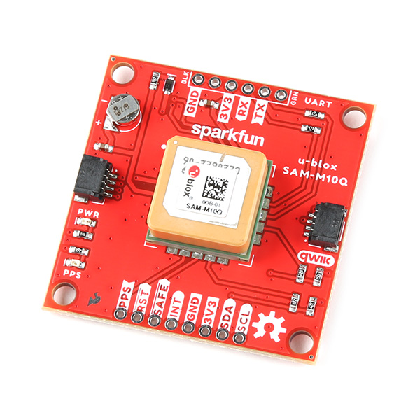
The SparkFun SAM-M10Q GPS Breakout features the the SAM-M10Q chip-antenna module from u-blox©. The M10Q line is the successor to u-blox's M8Q found on the SparkFun GPS Breakout - Chip Antenna, SAM-M8Q (Qwiic) and is a drop-in replacement with updated features to reduce power consumption while also improving performance. The SAM-M10Q can receive up to four GNSS constellations at once which improves time-to-fix and positional accuracy even in areas with limited view of the sky.
Utilizing our handy Qwiic system, no soldering is required to connect it to the rest of your system. However, the board still breaks out 0.1"-spaced pins for users who prefer a soldered connection or prototyping on a breadboard.Purchase from SparkFun
This guide covers the hardware present on this GPS breakout, how to assemble it into a Qwiic circuit and how to use it with the SparkFun u-blox Arduino Library v3.
Required Materials
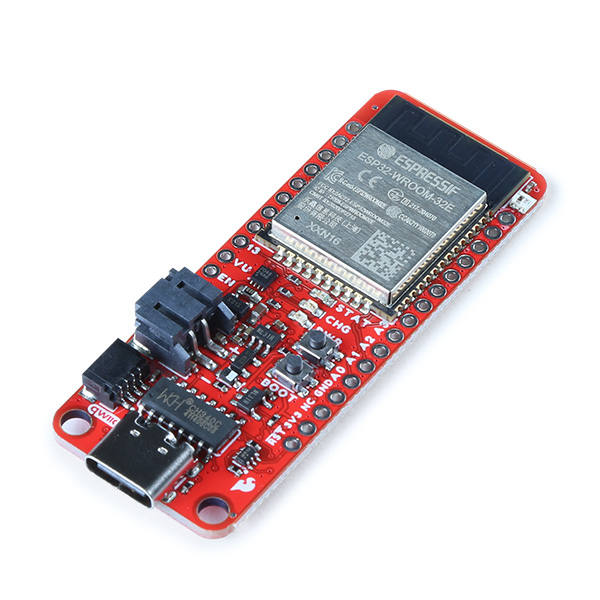
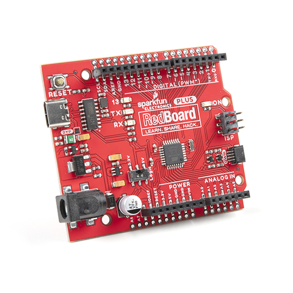
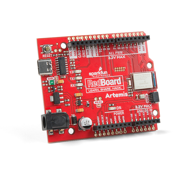
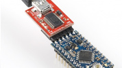
To follow along with this guide you will need a microcontroller to communicate with the SAM-M10Q Breakout. Below are a few options that come Qwiic-enabled out of the box:
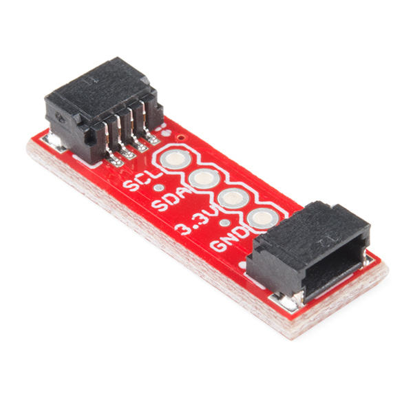
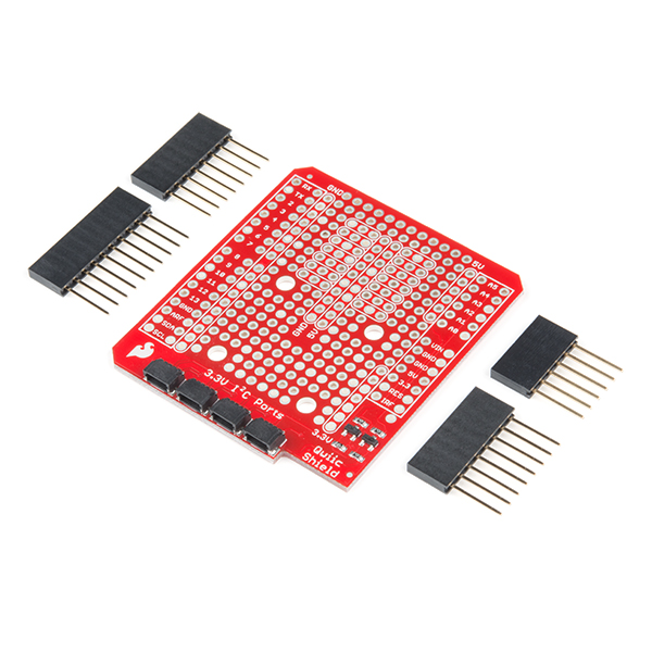
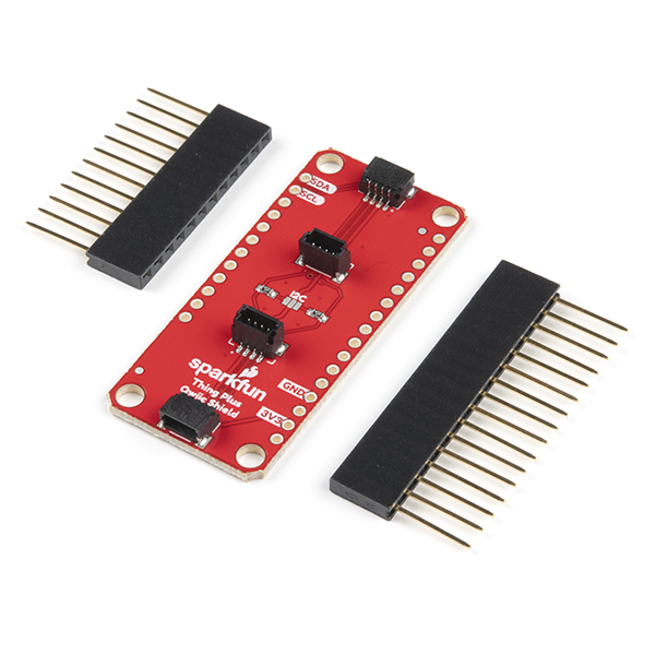
If your chosen microcontroller is not already Qwiic-enabled, you can add that functionality with one or more of the following items:
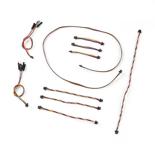
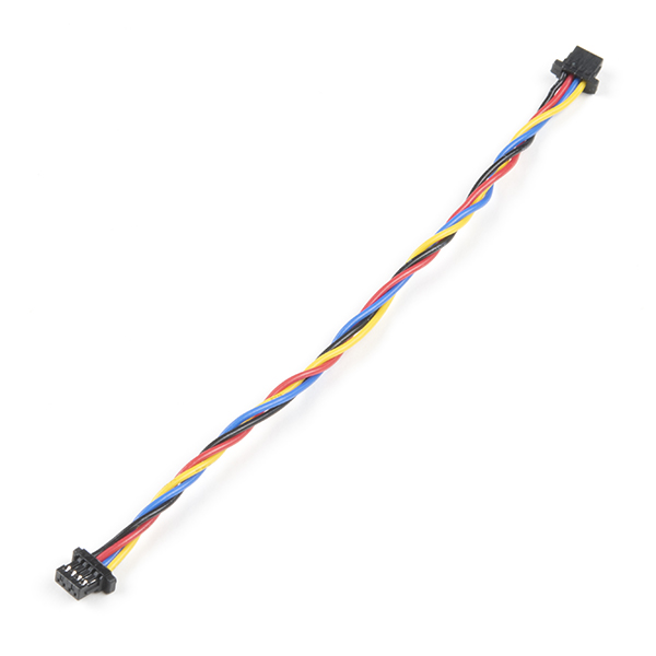
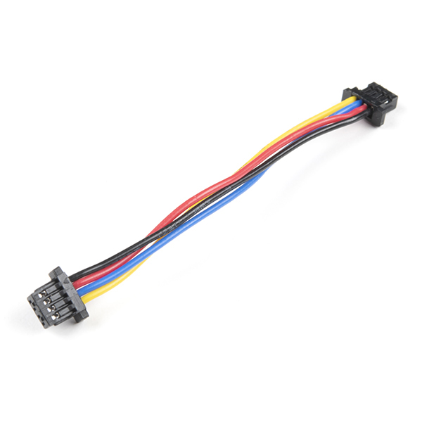
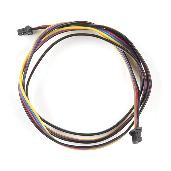
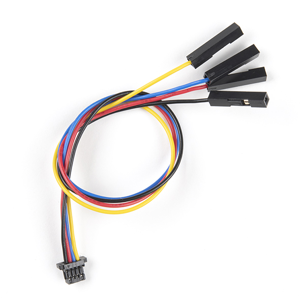
You will also need at least one Qwiic cable to connect your GPS breakout to your microcontroller:
Optional Materials
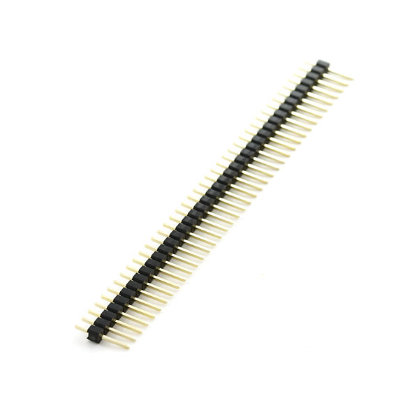
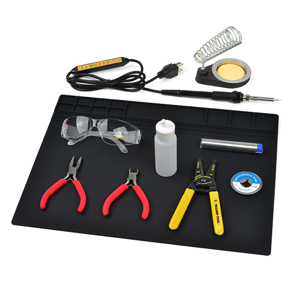
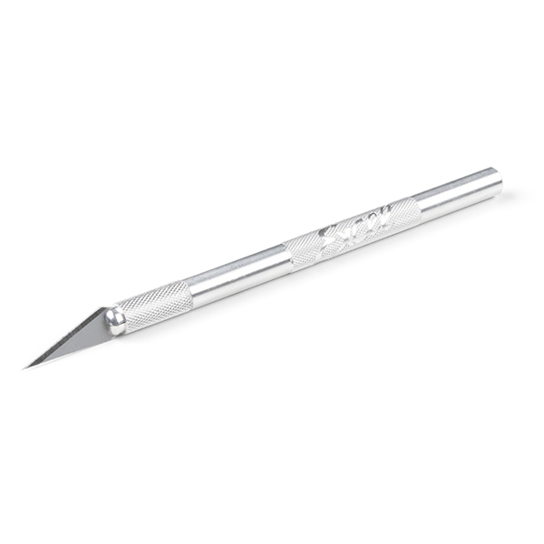
If you prefer a soldered connection or want to modify the solder jumpers on this board, you may need some of the products listed below:
Suggested Reading
We designed this board for integration into SparkFun's Qwiic connect system. Click on the banner below to learn more about the SparkFun Qwiic Connect System.

Before getting started with this Hookup Guide, you may want to read through the tutorials below if you are not familiar with the concepts covered in them or want a refresher. If you are using either of the Qwiic Shields linked above, we recommend reading through their respective Hookup Guides before continuing with this tutorial:

Hardware Overview
Let's take a closer look at the SAM-M10Q and other hardware on this GPS breakout.
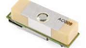
SAM-M10Q
The SAM-M10Q GNSS module from u-blox is from the M10 series of modules and features a chip antenna. The chip antenna removes the need for an external antenna and we designed this board to mount the module on a large ground plane to help maximize the reception quality.

The module can receive up to four GNSS constellations at a time allowing for excellent signal quality and reliability even in areas with limited view of the sky. More GNSS locks reduce the update rate of the SAM-M10Q so users should take into consideration which is more important for their application. The SAM-M10Q has a max altitude of 80,000m and max velocity of 500m/s with an acceleration limit of ≤ 4g. The module also has a time pulse signal with a RMS accuracy of 30ns. This signal defaults to 1 pulse per second but is configurable between 0.25Hz to 10MHz. For a complete overview of the SAM-M10Q refer to the datasheet and integration manual. The tables below outline some of the SAM-M10Q's capabilities in single-GNSS and multi-GNSS modes:
| Single GNSS Constellation Mode | ||||||
|---|---|---|---|---|---|---|
| Parameter | Condition | Units | GPS | GLONASS | Galileo | BeiDou |
| Horizontal Position Accuracy | - | m | 1.5 | 4 | 3 | 2 |
| Max Navigation Update Rate | - | Hz | 18 | 18 | 18 | 18 |
| Time-To-First-Fix | Cold Start | s | 29 | 27 | 41 | 56 |
| Hot Start | 1 | 1 | 1 | 1 | ||
| Sensitivity | Cold Start | dBm | -146 | -145 | -139 | -134 |
| Hot Start | -157 | -157 | -153 | -155 | ||
| Tracking and Navigation | -165 | -164 | -159 | -161 | ||
| Reacquisition | -158 | -156 | -152 | -154 |
| Multi-GNSS Constellation Modes | ||||||
|---|---|---|---|---|---|---|
| Parameter | Condition | Units | GPS+GAL+BDS+GLO | GPS+GAL+GLO | GPS+GAL+BDS | GPS+GAL |
| Max Navigation Update Rate | - | Hz | 5 | 7 | 8 | 10 |
| Horizontal Position Accuracy | - | m | 1.5 | 1.5 | 1.5 | 1.5 |
| Time-To-First-Fix | Cold Start | s | 23 | 23 | 28 | 28 |
| Hot Start | 1 | 1 | 1 | 1 | ||
| Sensitivity | Tracking and Navigation | dBm | -165 | -165 | -165 | -165 |
| Reacquisition | -158 | -158 | -158 | -158 | ||
| Cold Start | -146 | -146 | -146 | -146 | ||
| Hot Start | -157 | -157 | -157 | -157 |
Backup Battery
This breakout includes a small 3V/1mAh lithium battery to power relevant systems inside the SAM-M10Q that allow for a quick acquisition of satellites. On first start up, time to first fix is about ~23 seconds, but after it has a lock the battery allows for a hot start and can drop the time to fix down to one second. A hot start and lasts for four hours after the board is powered down and the board charges it slowly when powered.

Qwiic & Through Hole Connections
As the name suggests, this breakout includes a pair of Qwiic connectors to integrate the SAM-M10Q into an existing Qwiic system. The board also includes a pair of 0.1"-spaced plated through hole (PTH) headers for the SAM-M10Q's UART interface as well as several other function pins.

Qwiic Connectors
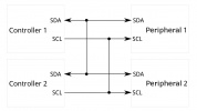
The two Qwiic connectors route the I2C lines (SDA/SCL) as well as 3.3V and Ground allowing for power and I2C communication with no soldering required. These connectors offer the best and easiest way to get started using this board with the SparkFun u-blox GNSS Arduino Library as many of the examples included in it assume an I2C connection between the SAM-M10Q and microcontroller.
Plated Through Hole Headers
The breakout also includes two sets of 0.1"-spaced plated through hole (PTH) headers. One routes the SAM-M10Q's UART interface to a header matching the pinout of our Serial Basic and other USB-to-UART boards. The other routes the I2C interface, interrupt (INT), safeboot (SAFE), reset (RST), and time pulse (PPS) pins.
The UART header mates with a 3.3V Serial Basic or other USB-to-UART converter. Make sure a connected converter runs at 3.3V and not 5V.
The PPS outputs pulse trains synchronized with the GPS or UTC time grid. The signal defaults to once per second but is configurable over a wide range. Read the u-blox Receiver Protocol Specification in the Resources and Going Further section for more information. The Reset (RST) pin resets the chip. The next pin, SAFE is used to start up the IC in safe boot mode. The final pin INT can be used to wake the chip from power save mode.
LEDs
The board has two LEDs labeled PWR and PPS. The Power (PWR) LED indicates when the board is powered. The Pulse Per Second (PPS) LED connects to the module's timepulse pin. This signal generates a pulse that is synchronized with a GPS or UTC time grid. By default, it pulses once every second but can be adjuted to different time values.

Solder Jumpers
There are three solder jumpers on the board labeled: I2CPUR, PWRLED and PPSLED.

The I2CPUR is a three-way jumper connecting the SDA/SCL lines to 3.3V through a pair of 2.2kΩ resistors. Open the jumper completely by severing the traces between all three pads to disable the pullup resistors on the I2C bus. The other two jumpers complete the power circuits for their respective LEDs (Power and Pulse Per Second). Open the solder jumpers to disable these LEDs to reduce total power consumption of the board.
Board Dimensions
This GPS breakout is slightly bigger than a typical Qwiic board due to the expanded ground plane around the SAM-M10Q module and measures 1.6" x 1.6" (40.64mm x 40.64mm). The board includes four mounting holes that fit a 4-40 screw.

Hardware Assembly
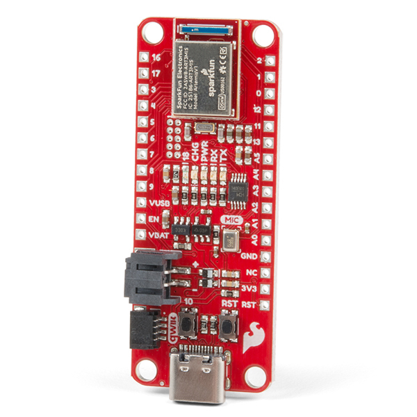
Now that we're familiar with the hardware on this breakout, let's assemble it into a Qwiic circuit with the SparkFun RedBoard Artemis.
Qwiic Assembly
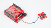
With the Qwiic system, simply connect the GNSS Breakout to your chosen Qwiic-enabled microcontroller (in this case the RedBoard Artemis) using a Qwiic cable like the image below:

Since the SAM-M10Q has an on-chip antenna, no external antenna is required so just plug your microcontroller into your computer and start using the board with the SparkFun u-blox Arduino Library.
Soldered Assembly
If you prefer to configure and use the SAM-M10Q's with u-center either through UART or I2C or if you want a traditional soldered connection should solder to the board's PTH headers. If you've never done through-hole soldering before or would like a refresher or tips, check out our How to Solder: Through-Hole Soldering tutorial:

Software Overview
The SAM-M10Q works with the latest version of the SparkFun u-blox GNSS Arduino Library, v3. Install the library using Arduino's Library Manager Tool by searching for 'SparkFun u-blox GNSS v3'. If you prefer to manually install the library you can download the GitHub repository or download a ZIP of it here:
The third version of this library complies with u-blox's updated UBX protocol that depreciates the UBX-CFG commands. These still work but are depreciated and u-blox now recommends using the updated VALSET, VALGET, and VALDEL commands included in v3 of the library. With the library installed, let's move on to taking a look at a couple of examples from the library.
Arduino Examples
Now let's take a closer look at the basic GNSS position example included in the SparkFun u-blox GNSS Arduino Library.
Example 1 - Position, Velocity, Time
The first example in the library demonstrates initializing the SAM-M10Q (or any other supported u-blox module) and then receiving position, velocity, and time data from the module. Open the example by navigating to 'File' < 'Examples' < 'SparkFun u-blox GNSS v3' < 'Example1_PositionVelocityTime'. Select your Board and Port and click 'Upload. Once the code finishes uploading, open the serial monitor with the baud set to 115200.
For the best results, make sure the SAM-M10Q has a clear view of the open sky. The first time running this example will take ~23 seconds for the module to get a lock onto any satellites. After this initial cold start, the battery on the board will provide power to the hot start circuitry in the module to assist with warm/hot starts during power cycles to drop the time-to-fix down to just one second. This hot start lasts up to four hours between power cycles.
Troubleshooting
Need Help?
If you need technical assistance or more information on a product that is not working as you expected, we recommend heading on over to the SparkFun Technical Assistance page for some initial troubleshooting.
If you can't find what you need there, the SparkFun Forums is a great place to search product forums and ask questions.
Account Registration Required
If this is your first visit to our forum, you'll need to create a Forum Account to post questions.
Resources:
That's all for this tutorial. For more information about the SparkFun GPS Breakout - Chip Antenna, SAM-M10Q (Qwiic), take a look at the following resources: