Introduction
|
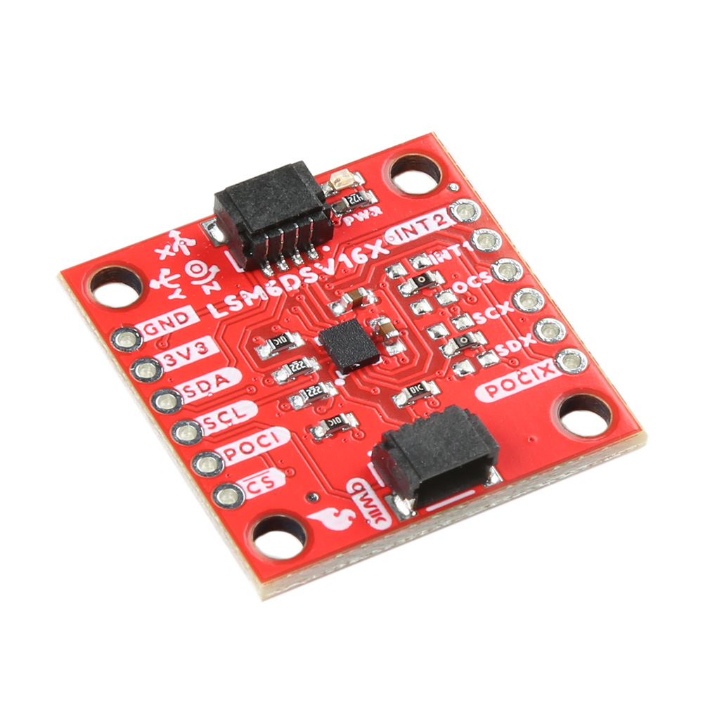
The SparkFun 6DoF - LSM6DSV16X (Qwiic) is a Qwiic enabled board based on the LSM6DSV16X from STMicroelectronics. This little chip is a high-performance, low-power 6-axis IMU, featuring a 3-axis digital accelerometer and a 3-axis digital gyroscope, with a triple core for processing acceleration and angular rate data on three separate channels (user interface, OIS, and EIS) with dedicated configuration, processing, and filtering. |
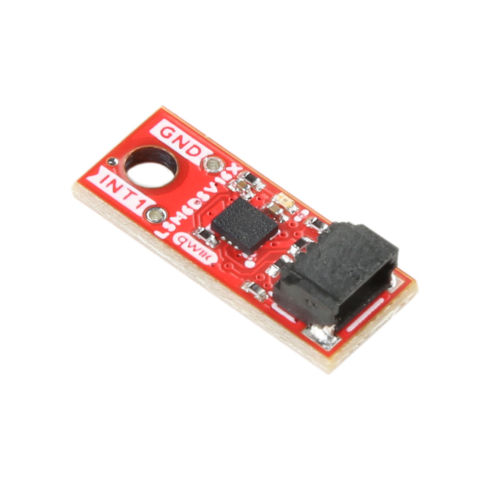
The SparkFun 6DoF Micro- LSM6DSV16X (Qwiic) is the 1x1's mini-me, containing most of it's elder sibling's functionality in a tiny little package. |
Required Materials
To follow along with this tutorial, you will need the following materials. You may not need everything though depending on what you have. Add it to your cart, read through the guide, and adjust the cart as necessary.
Suggested Reading
If you aren’t familiar with the following concepts, we recommend checking out these tutorials before continuing.
Hardware Overview
Accelerometer - LSM6DSV16X
The LSM6DSV16X Accelerometer from STMicroelectronics has a few different modes:
- Mode 1: Periperhal only mode - I2C or SPI
- Mode 2: Sensor hub mode - I2C or SPI with controller I2C port
- Mode 3 and 4: AUX SPI mode I2C and SPI access multi-read
|
|
|


Mode 1
This is the default "peripheral only" mode. This mode allows you to use either I2C or SPI. By default, I2C is enabled with an address of 0x6B. By manipulating the associated jumper, you can change the I2C address to 0x6A (cut the power side and close the ground side) or switch to SPI mode (both jumpers open).
Mode 2
This mode enables a secondary I2C port that the 6DoF controls; up to 4 external sensors can be connected to the I2C controller interface of the device. External sensors communicate via the SCX and SDX (PICOX) lines - the SCX and SDX jumpers will need to be opened.
Modes 3 & 4
In addition to the primary I2C peripheral interface or SPI (3- / 4-wire) serial interface, an auxiliary SPI (3- / 4-wire) serial interface is available for external device connections (i.e. camera module). Mode 3 is available for gyroscope only, Mode 4 is available for both gyroscope and accelerometer.
The analog hub and Qvar functionalities are available in mode 1 with I²C interface only.
Qwiic Connector
The Qwiic connector(s) on the SparkFun 6DoF - LSM6DSV16X (Qwiic) and SparkFun 6DoF Micro - LSM6DSV16X (Qwiic) provide power and I2C connectivity simultaneously.
|
|
|


Power
Ideally, power to these boards will be provided by the Qwiic cables. However, should you wish to provide power separately, the 1" x 1" board has its pins broken out to PTH and you can wire up power via these.
Warning
Make sure to pay attention to logic levels - supply voltage range should be between 1.71V - 3.6V.

LSM6DSV16X Power Pins
GPIO
This is a quick overview of the pin functionality. For more information, refer to the datasheet.
I2C
If you do not want to use the Qwiic connectors, I2C functionality has been broken out to PTH pins on the 1x1" board.

LSM6DSV16X I2C Pins
SPI
Primary SPI functionality has been broken out to the highlighted pins below.

LSM6DSV16X SPI Pins
Auxiliary SPI is available via AH1, AH2, and OCS.

LSM6DSV16X Aux SPI Pins
AH1/AH2
The LSM6DSV16X embeds Qvar functionality, which is an electrostatic sensor able to measure the variation of the quasi-electrostatic potential. The Qvar sensing channel can be used for user interface applications like tap, double tap, triple tap, long press, and L/R – R/L swipe. Functionality is accessed via the AH1 and AH2 pins. For more information, refer to STMicroelectronics' Qvar Sensing Channel Application Notes.

LSM6DSV16X Qvar Pins
Interrupt Pins
Interrupt functionality is available via the INT pins. There are two interrupts available on the 1x1" board, and 1 interrupt available on the Micro. These pins are configurable to be high or low.
|
|
|


Jumpers
I2C
Like our other Qwiic boards, the Qwiic 6DoF - LSM6DSV16X boards come equipped with pull-up resistors on the clock and data pins. If you are daisy-chaining multiple Qwiic devices, you will want to cut this jumper; if multiple sensors are connected to the bus with the pull-up resistors enabled, the parallel equivalent resistance will create too strong of a pull-up for the bus to operate correctly. As a general rule of thumb, disable all but one pair of pull-up resistors if multiple devices are connected to the bus. To disable the pull up resistors, use an X-acto knife to cut the joint between the two jumper pads highlighted below.
|
|
|


I2C Address
The SparkFun 6DoF - LSM6DSV16X (Qwiic) boards have a default I2C address of 0x6B, but by cutting the address jumper on the back of the board, you can select 0x6A (GND) or SPI (fully open).
|
|
|


SDX/SCX
If using either Mode 2 (sensor hub mode) or the analog capabilities of the sensor, cut both of these traces.

LSM6DSV16X SCX/SDX Jumpers
Pad Jumpers
When using the Analog In (QVar) functionality, you can select whether P1 is tied to GND or 3v3 using the PAD1 jumper. Similarly, you can select whether P2 is tied to GND or 3v3 using the PAD2 jumper. Refer to either the application notes for more information.

LSM6DSV16X Pad Jumpers
LED
Let there be light! Or not. An LED on the front of each board indicates power is being provided to the board. If you don't like LEDs or you are concerned about current draw, cut the jumper highlighted below.
|
|
|


Board Outline
The SparkFun 6DoF - LSM6DSV16X (Qwiic) follows the standard 1" x 1" convention of most of our Qwiic breakout boards.

SparkFun 6DoF - LSM6DSV16X (Qwiic)
The SparkFun 6DoF Micro - LSM6DSV16X (Qwiic) measures 0.3" x 0.75".

SparkFun 6DoF Micro - LSM6DSV16X (Qwiic)
Hardware Assembly
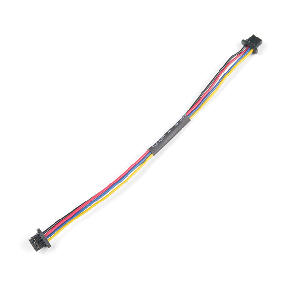
The delightful thing about our Qwiic boards is that they are quite literally plug and play.

SparkFun 6DoF - LSM6DSV16X (Qwiic) Plugged into the RedBoard Qwiic

SparkFun 6DoF Micro - LSM6DSV16X (Qwiic) Plugged into the RedBoard Qwiic
Attention
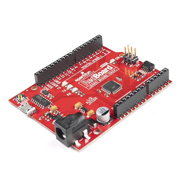
If you are using the SparkFun RedBoard Qwiic, make sure that you have your I/O jumper set correctly. You'll find the 3V3 vs 5V jumper on the front of the RedBoard Qwiic. You'll need to cut the connective trace to 5V and solder the center jumper pad to the 3V3 pad in order for the examples to work. More information can be found in the RedBoard Qwiic Hookup Guide.
Software Setup and Programming
Attention
If this is your first time using Arduino, please review our tutorial on installing the Arduino IDE. If you have not previously installed an Arduino library, please check out our installation guide.
SparkFun has written a library to work with the SparkFun LSM6DSV16X Boards. You can obtain this library through the Arduino Library Manager by searching for "LSM6DSV16X" and installing the latest version. If you prefer downloading libraries manually, you can grab them from the GitHub Repository.
Arduino Examples
Example 1: Basic Readings
This first example just does some basic measurements. To find Example 1, go to File > Examples > SparkFun 6DoF LSM6DSV16X > example1_basic:

Finding Example 1
Alternatively, you can expand the link below and copy and paste the code into a shiny new Arduino sketch:
Example 1 Arduino Code
/*
  example1-basic

  This example shows the basic settings and functions for retrieving accelerometer
    and gyroscopic data.

  Written by Elias Santistevan @ SparkFun Electronics, May, 2022

    Products:

    SparkFun 6DoF LSM6DSV16X (Qwiic):
        https://www.sparkfun.com/products/21325

    SparkFun Micro 6DoF LSM6DSV16X (Qwiic):
        https://www.sparkfun.com/products/21336

  Repository:
        https://github.com/sparkfun/SparkFun_LSM6DSV16X_Arduino_Library

  SparkFun code, firmware, and software is released under the MIT
    License (http://opensource.org/licenses/MIT).
*/

#include "SparkFun_LSM6DSV16X.h"
#include <Wire.h>

SparkFun_LSM6DSV16X myLSM;

// Structs for X,Y,Z data
sfe_lsm_data_t accelData;
sfe_lsm_data_t gyroData;

void setup()
{

    Wire.begin();

    Serial.begin(115200);
    while (!Serial)
    {
    }

    Serial.println("LSM6DSV16X Example 1 - Basic Readings I2C");

    if (!myLSM.begin())
    {
        Serial.println("Did not begin, check your wiring and/or I2C address!");
        while (1)
            ;
    }

    // Reset the device to default settings. This if helpful is you're doing multiple
    // uploads testing different settings.
    myLSM.deviceReset();

    // Wait for it to finish reseting
    while (!myLSM.getDeviceReset())
    {
        delay(1);
    }

    Serial.println("Board has been Reset.");
    Serial.println("Applying settings.");

    // Accelerometer and Gyroscope registers will not be updated
    // until read.
    myLSM.enableBlockDataUpdate();

    // Set the output data rate and precision of the accelerometer
    myLSM.setAccelDataRate(LSM6DSV16X_ODR_AT_7Hz5);
    myLSM.setAccelFullScale(LSM6DSV16X_16g);

    // Set the output data rate and precision of the gyroscope
    myLSM.setGyroDataRate(LSM6DSV16X_ODR_AT_15Hz);
    myLSM.setGyroFullScale(LSM6DSV16X_2000dps);

    // Enable filter settling.
    myLSM.enableFilterSettling();

    // Turn on the accelerometer's filter and apply settings.
    myLSM.enableAccelLP2Filter();
    myLSM.setAccelLP2Bandwidth(LSM6DSV16X_XL_STRONG);

    // Turn on the gyroscope's filter and apply settings.
    myLSM.enableGyroLP1Filter();
    myLSM.setGyroLP1Bandwidth(LSM6DSV16X_GY_ULTRA_LIGHT);

    Serial.println("Ready.");
}

void loop()
{

    // Check if both gyroscope and accelerometer data is available.
    if (myLSM.checkStatus())
    {
        myLSM.getAccel(&accelData);
        myLSM.getGyro(&gyroData);
        Serial.print("Accelerometer: ");
        Serial.print("X: ");
        Serial.print(accelData.xData);
        Serial.print(" ");
        Serial.print("Y: ");
        Serial.print(accelData.yData);
        Serial.print(" ");
        Serial.print("Z: ");
        Serial.print(accelData.zData);
        Serial.println(" ");
        Serial.print("Gyroscope: ");
        Serial.print("X: ");
        Serial.print(gyroData.xData);
        Serial.print(" ");
        Serial.print("Y: ");
        Serial.print(gyroData.yData);
        Serial.print(" ");
        Serial.print("Z: ");
        Serial.print(gyroData.zData);
        Serial.println(" ");
    }

    delay(100);
}
Make sure you've selected the correct board and port in the Tools menu and then hit the upload button. Once the code has finished uploading, go ahead and open a Serial Monitor. You should see something similar to the following. Note the obvious changes where the sensor was turned upright.

Example 1 Output
Example 2: Interrupt
This example shows the basic settings and functions for retrieving accelerometer data. In addition we're setting the data ready signal to interrupt pin one in an active high configuration and show additional ways in which the interrupts can be configured. To find Example 2, go to File > Examples > SparkFun 6DoF LSM6DSV16X > example2_interrupt.

Finding Example 2
Alternatively, you can expand the link below and copy and paste the code into a shiny new Arduino sketch:
Example 2 Arduino Code
/*
  example2-interrupt

  This example shows the basic settings and functions for retrieving accelerometer
    data. In addition we're setting the data ready signal to interrupt pin one in an
    active high configuration and show additional ways in which the interrupts
    can be configured.

  Written by Elias Santistevan @ SparkFun Electronics, May 2022

    Products:

    SparkFun 6DoF LSM6DSV16X (Qwiic):
        https://www.sparkfun.com/products/21325

    SparkFun Micro 6DoF LSM6DSV16X (Qwiic):
        https://www.sparkfun.com/products/21336

  Repository:
        https://github.com/sparkfun/SparkFun_LSM6DSV16X_Arduino_Library

  SparkFun code, firmware, and software is released under the MIT
    License (http://opensource.org/licenses/MIT).
*/

#include "SparkFun_LSM6DSV16X.h"
#include <Wire.h>

// Structs for X,Y,Z data
SparkFun_LSM6DSV16X myLSM;

// Structs for X,Y,Z data
sfe_lsm_data_t accelData;

// Interrupt pin
byte interrupt_pin = 10;

void setup()
{

    // Set the interrupt to INPUT
    pinMode(interrupt_pin, INPUT);

    Serial.begin(115200);
    while (!Serial)
    {
    }

    Serial.println("LSM6DSV16X Example 2 - Interrupts");

    Wire.begin();

    if (!myLSM.begin())
    {
        Serial.println("Did not begin, check your wiring and/or I2C address!");
        while (1)
            ;
    }

    // Reset the device to default settings. This is helpful if you're doing multiple
    // uploads testing different settings.
    myLSM.deviceReset();

    // Wait for it to finish reseting
    while (!myLSM.getDeviceReset())
    {
        delay(1);
    }

    Serial.println("Board has been Reset.");
    Serial.println("Applying settings.");

    // Accelerometer and Gyroscope registers will not be updated
    // until read.
    myLSM.enableBlockDataUpdate();

    // Set the output data rate and precision of the accelerometer
    myLSM.setAccelDataRate(LSM6DSV16X_ODR_AT_7Hz5);
    myLSM.setAccelFullScale(LSM6DSV16X_16g);

    // Turn on the accelerometer's filter and apply settings.
    myLSM.enableAccelLP2Filter();
    myLSM.setAccelLP2Bandwidth(LSM6DSV16X_XL_STRONG);

    // Set the accelerometer's status i.e. the data ready to interrupt one.
    // Commented out just below is the function to send the data ready
    // to interrupt two.

    myLSM.setIntAccelDataReady(LSM_PIN_ONE);
    // myLSM.setIntAccelDataReady(LSM_PIN_TWO);

    // We can just as easily set the gyroscope's data read signal to either interrupt

    // myLSM.setIntGyroDataReady(LSM_PIN_ONE);
    // myLSM.setIntGyroDataReady(LSM_PIN_TWO);

    // Uncommenting the function call below will change interrupt TWO
    // active LOW instead of HIGH.

    // myLSM.setInt2DENActiveLow();

    // This function call will modify which "events" trigger an interrupt. No
    // argument has been given, please refer to the datasheet for more
    // information.

    // Possible values for routing your interrupt include:
    // lsm6dsv16x_pin_int_route_t routeInt;
    // routeInt.drdy_xl = 1;
    // routeInt.drdy_g = 1;
    // routeInt.drdy_g = 1;
    // routeInt.single_tap = 1;
    // routeInt.double_tap = 1;
    // myLSM.setIntRoute(routeInt, LSM_PIN_ONE);

    // This function changes the latching behaviour of the interrupts to pulsed.
    // lsm6dsv16x_data_ready_mode_t mode = LSM6DSV16X_DRDY_PULSED;
    // myLSM.setDataReadyMode();

    Serial.println("Ready.");
}

void loop()
{

    if (digitalRead(interrupt_pin) == HIGH)
    {
        myLSM.getAccel(&accelData);
        Serial.print("Accelerometer: ");
        Serial.print("X: ");
        Serial.print(accelData.xData);
        Serial.print(" ");
        Serial.print("Y: ");
        Serial.print(accelData.yData);
        Serial.print(" ");
        Serial.print("Z: ");
        Serial.print(accelData.zData);
        Serial.println(" ");
    }

    delay(100);
}
Your setup should resemble something like this:

Example 2
Make sure your code matches the pin you've selected as the interrupt pin. Here Pin 2 is wired as the interrupt pin on the RedBoard, so the code was modified to reflect that. Again, make sure you've selected the correct board and port in the Tools menu and then hit the upload button. Once the code has finished uploading, go ahead and open a Serial Monitor. You should see something similar to the following.

Example 2 Output
Example 3: SPI
This example shows the basic settings and functions for retrieving accelerometer and gyroscopic data but using the SPI interface. Everything other than that is identical to the "basic" example. To find Example 3, go to File > Examples > SparkFun 6DoF LSM6DSV16X > example3_spi:

Finding Example 3
Alternatively, you can expand the link below and copy and paste the code into a shiny new Arduino sketch:
Example 3 Arduino Code
/*
  example3-spi

  This example shows the basic settings and functions for retrieving accelerometer
    and gyroscopic data but using the SPI interface. Everything other than that is
    identical to the "basic" example.

  Written by Elias Santistevan @ SparkFun Electronics, May 2022

    Products:

    SparkFun 6DoF LSM6DSV16X (Qwiic):
        https://www.sparkfun.com/products/21325

    SparkFun Micro 6DoF LSM6DSV16X (Qwiic):
        https://www.sparkfun.com/products/21336

  Repository:
        https://github.com/sparkfun/SparkFun_LSM6DSV16X_Arduino_Library

  SparkFun code, firmware, and software is released under the MIT
    License (http://opensource.org/licenses/MIT).
*/

#include "SparkFun_LSM6DSV16X.h"
#include <SPI.h>

// SPI instance class call
SparkFun_LSM6DSV16X_SPI myLSM;

// Structs for X,Y,Z data
sfe_lsm_data_t accelData;
sfe_lsm_data_t gyroData;

// Set your chip select pin according to your setup.
int chipSelect = 10;

void setup()
{

    SPI.begin();

    Serial.begin(115200);
    while (!Serial)
    {
    }

    Serial.println("LSM6DSV16X Example 3 - Basic Readings SPI");

    pinMode(chipSelect, OUTPUT);
    digitalWrite(chipSelect, HIGH);

    if (!myLSM.begin(chipSelect))
    {
        Serial.println("Did not begin, check your wiring and/or I2C address!");
        while (1)
            ;
    }

    // Reset the device to default settings. This if helpful is you're doing multiple
    // uploads testing different settings.
    myLSM.deviceReset();

    // Wait for it to finish reseting
    while (!myLSM.getDeviceReset())
    {
        delay(1);
    }

    Serial.println("Board has been Reset.");
    Serial.println("Applying settings.");

    // Accelerometer and Gyroscope registers will not be updated
    // until read.
    myLSM.enableBlockDataUpdate();

    // Set the output data rate and precision of the accelerometer
    myLSM.setAccelDataRate(LSM6DSV16X_ODR_AT_7Hz5);
    myLSM.setAccelFullScale(LSM6DSV16X_16g);

    // Set the output data rate and precision of the gyroscope
    myLSM.setGyroDataRate(LSM6DSV16X_ODR_AT_15Hz);
    myLSM.setGyroFullScale(LSM6DSV16X_2000dps);

    // Enable filter settling.
    myLSM.enableFilterSettling();

    // Turn on the accelerometer's filter and apply settings.
    myLSM.enableAccelLP2Filter();
    myLSM.setAccelLP2Bandwidth(LSM6DSV16X_XL_STRONG);

    // Turn on the gyroscope's filter and apply settings.
    myLSM.enableGyroLP1Filter();
    myLSM.setGyroLP1Bandwidth(LSM6DSV16X_GY_ULTRA_LIGHT);

    Serial.print("Ready.");
}

void loop()
{

    // Check if both gyroscope and accelerometer data is available.
    if (myLSM.checkStatus())
    {
        myLSM.getAccel(&accelData);
        myLSM.getGyro(&gyroData);
        Serial.print("Accelerometer: ");
        Serial.print("X: ");
        Serial.print(accelData.xData);
        Serial.print(" ");
        Serial.print("Y: ");
        Serial.print(accelData.yData);
        Serial.print(" ");
        Serial.print("Z: ");
        Serial.print(accelData.zData);
        Serial.println(" ");
        Serial.print("Gyroscope: ");
        Serial.print("X: ");
        Serial.print(gyroData.xData);
        Serial.print(" ");
        Serial.print("Y: ");
        Serial.print(gyroData.yData);
        Serial.print(" ");
        Serial.print("Z: ");
        Serial.print(gyroData.zData);
        Serial.println(" ");
    }

    delay(100);
}
The wiring for this example is fairly straight forward, if somewhat ugly. Here's what it looks like:

Example 3
And here are the connections:
| Pin Connections | |
|---|---|
| Qwiic Breakout Pin | RedBoard Pin |
| PICO | 11 |
| POCI | 12 |
| SCLK | 13 |
| CS | A4 |
Once you get the correct port and board selected and the code is uploaded, you should see something like the following:

Example 3 Output
Attention
If you are using the SparkFun RedBoard Qwiic and your output only says "Reset. Applying Settings." with no other output, make sure that you have your I/O jumper set correctly. You'll find the 3V3 vs 5V jumper on the front of the RedBoard Qwiic. You'll need to cut the connective trace to 5V and solder the center jumper pad to the 3V3 pad. More information can be found in the RedBoard Qwiic Hookup Guide.
Further Examples
There are a few more examples in the library that get you started with I2C speeds, Qvar, and single/double tap. Feel free to explore and play with these examples to maximize your use of the SparkFun 6DoF - LSM6DSV16X (Qwiic) or SparkFun Micro 6DoF - LSM6DSV16X (Qwiic)!
Troubleshooting
Note
Not working as expected and need help?
If you need technical assistance and more information on a product that is not working as you expected, we recommend heading on over to the SparkFun Technical Assistance page for some initial troubleshooting.
If you don't find what you need there, the SparkFun Forums are a great place to find and ask for help. If this is your first visit, you'll need to create a Forum Account to search product forums and post questions.