Hardware Overview
Digi XBee® Smart Modem Socket
We've kept the Digi XBee socket consistent with the Digi XBee pinout, so this breakout board is backwards compatible. In order to take full advantage of this board, we recommend one of the newer Digi XBee boards. The Digi XBee® 3 Low-Power LTE-M/NB-IoT, GNSS, no SIM is a great bet.
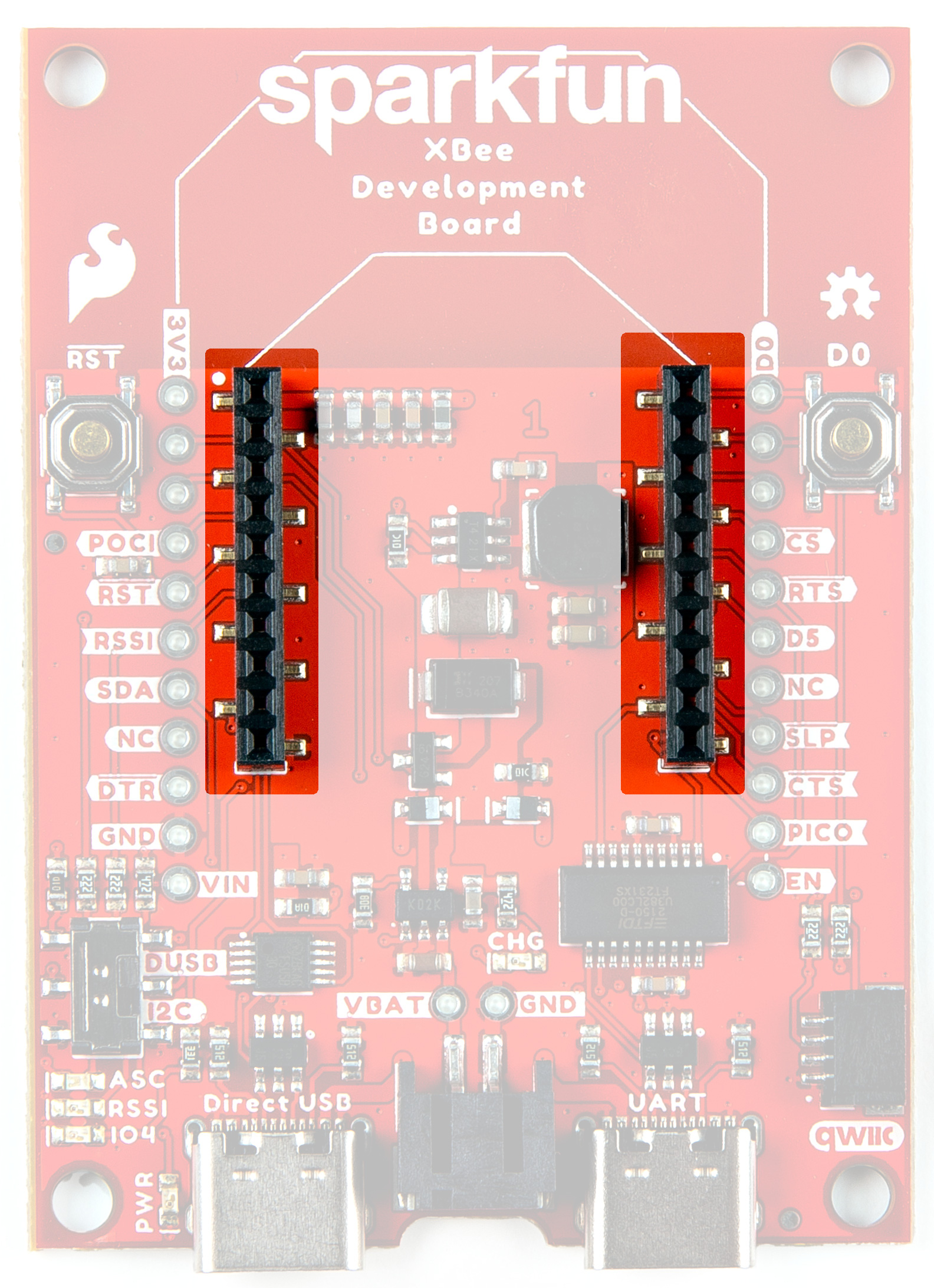
Digi XBee Socket
Power and USB-C Connectors
There are two USB-C connectors on the board that can provide power. Both can be plugged in simulatenously. Input VCC range is between 3.3V-5.5V.
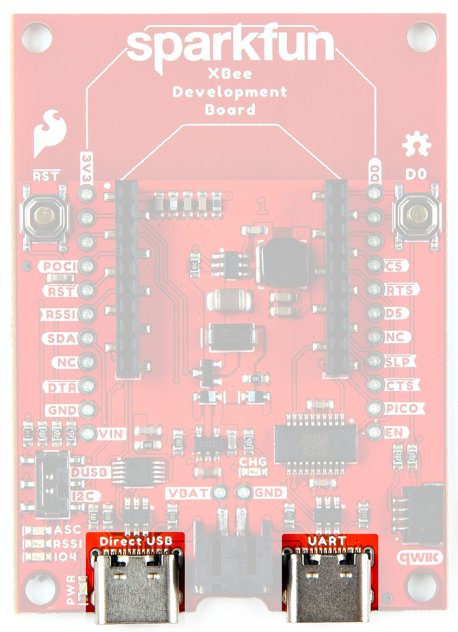
USB-C
Direct USB
Digi XBee 3 modules with cellular capabilities have a u-blox cell module. The firmware for this module can be updated directly from the "Direct USB" USB-C connector. For more information, please refer to the Digi XBee® 3 Cat1 Smart Modem User Guide.
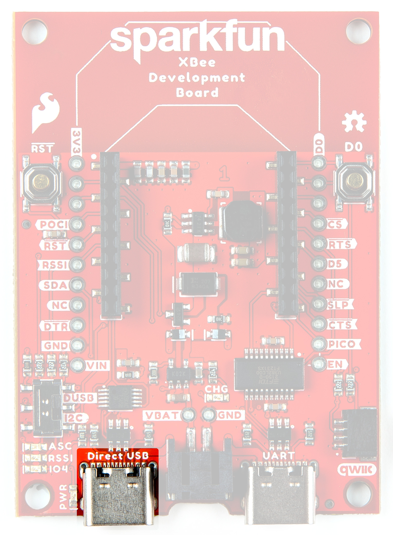
Direct USB-C
Qwiic Connector
The Qwiic connector on the SparkFun Digi XBee® Development Board provides power and I2C connectivity to Qwiic breakout boards. Note that I2C functionality is not enabled by default.
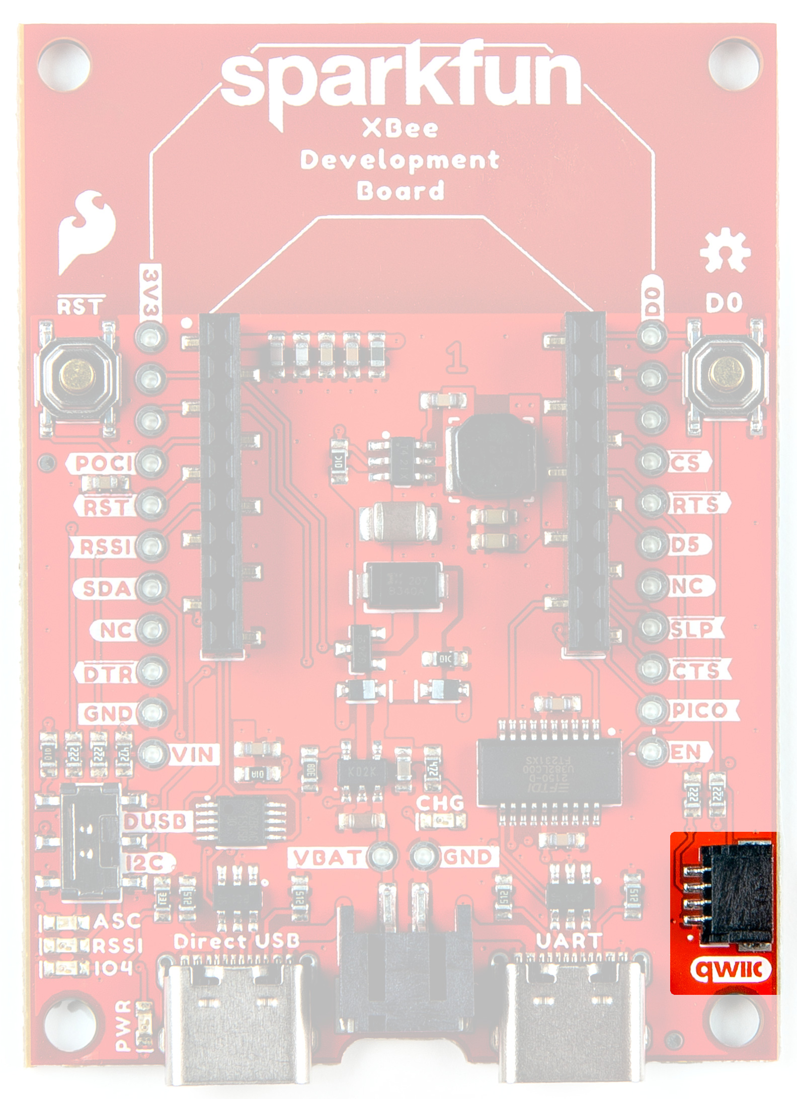
Qwiic Connector
USB Switch
The USB switch allows you to select between Direct USB and I2C. Default is Low (I2C/SDA).
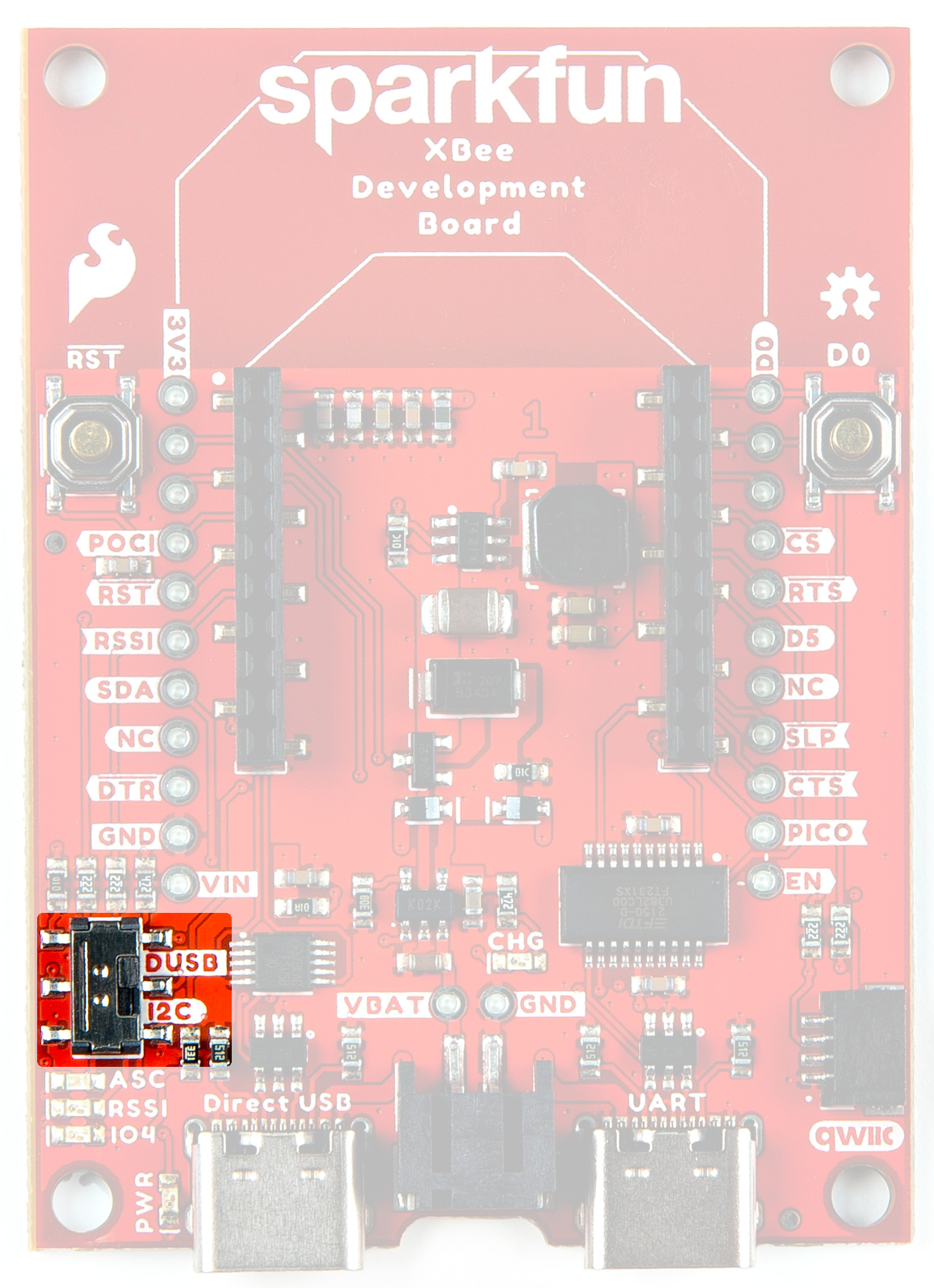
DUSB I2C Switch
Buck Converter - AP63203
The AP63203 is a 2A, synchronous buck converter with a wide input voltage range that fully integrates a 125mΩ high-side power MOSFET and a 68mΩ lowside power MOSFET to provide high-efficiency step-down DC/DC conversion. VIN range is 3.8V-5.5V. Output is 2A max.
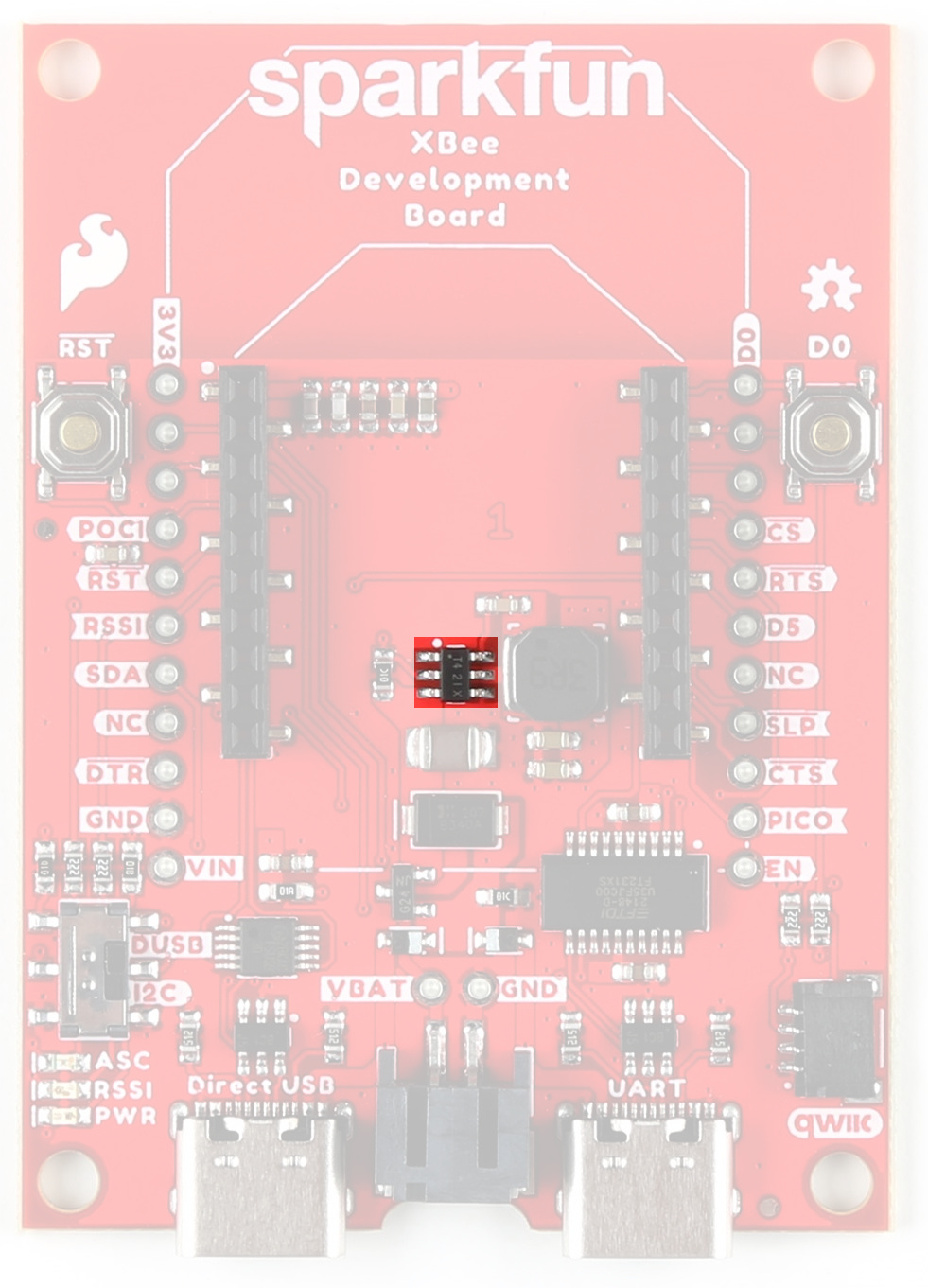
AP63203 Buck Converter
USB to UART Bridge
The FT231XS translates data between your computer and the Digi XBee. This is one of our favorite chips because it supports all computer platforms and it's easy to work with. If this is the first FTDI chip you've ever connected to your computer (it probably won't be your last), there is some driver installation to get out of the way. We've written a tutorial detailing How to Install FTDI Drivers tutorial.
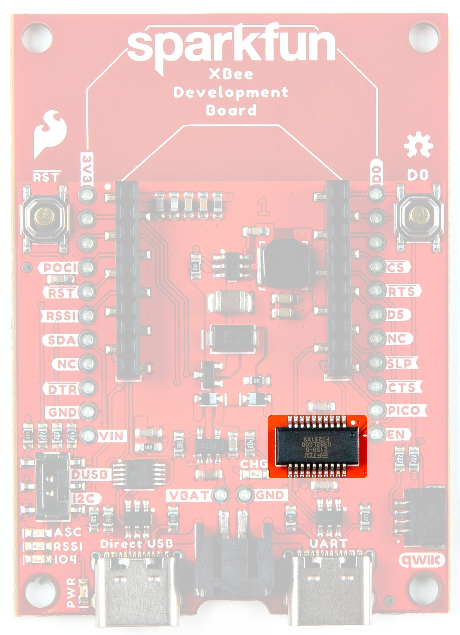
FT231XS USB to UART Bridge
Lipo Battery Connector
The SparkFun Digi XBee® Development Board includes support for single-cell lithium-polymer (LiPo) batteries, which plug into the board's black 2-pin JST connector. LiPos are perfect for projects on-the-go, or those that just need a little extra oomph. Bonus - you can charge your LiPo battery if the board is also plugged in.
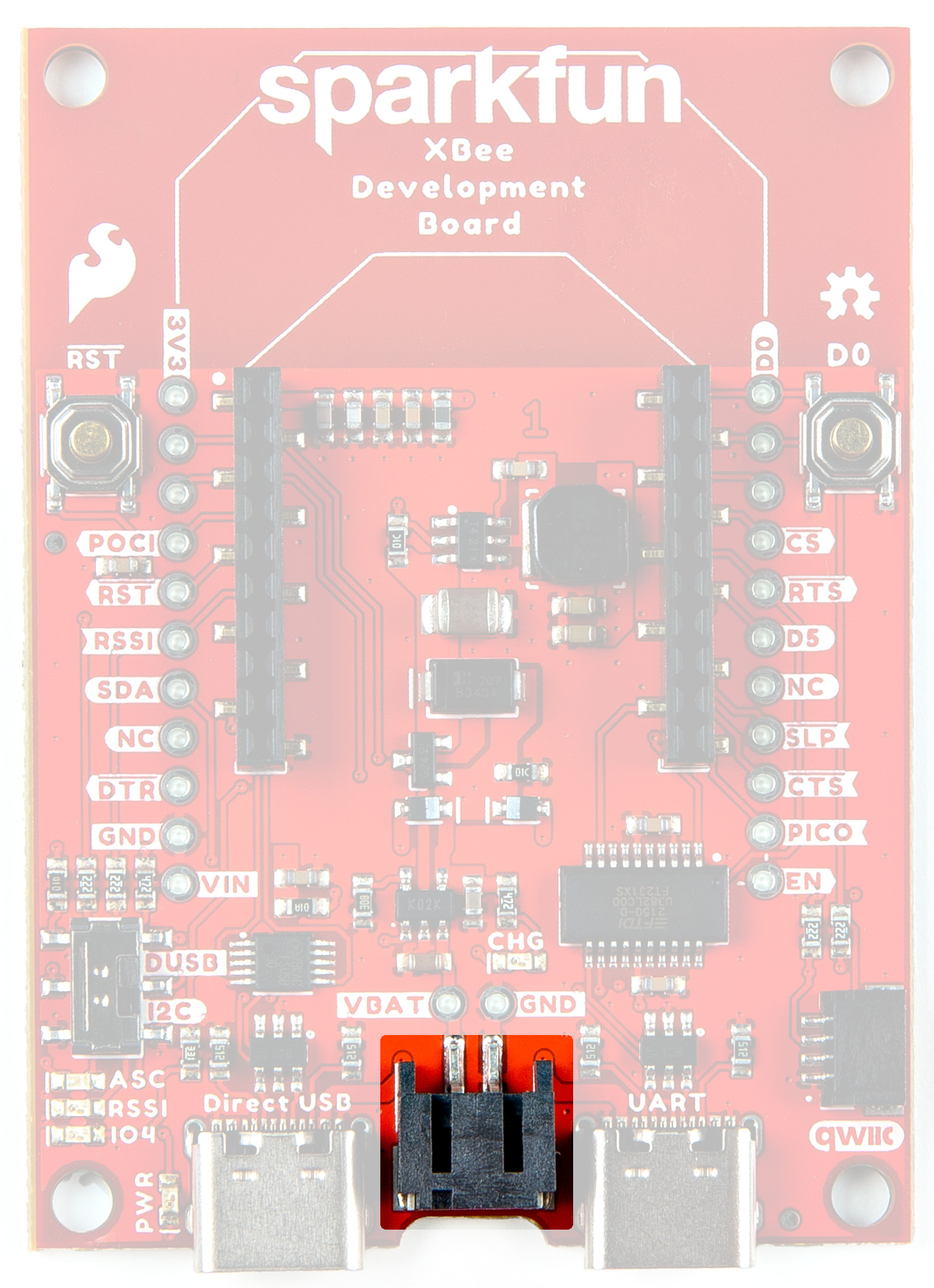
Battery Connector
GPIO
We've broken out the Digi XBee pins to plated through holes on either side of the board.
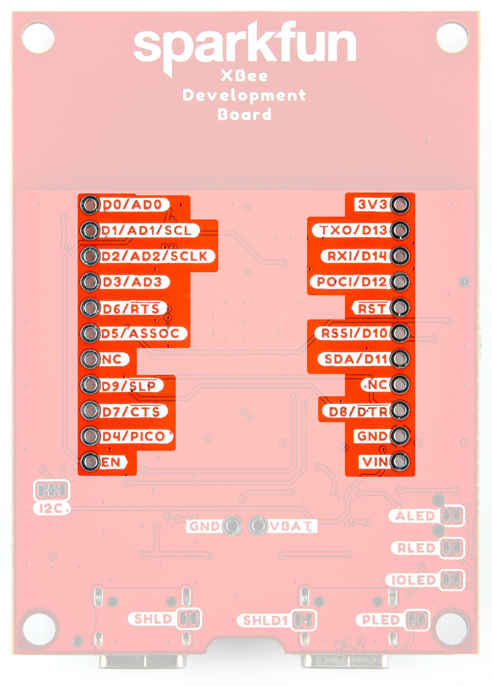
GPIO
Buttons
There are two buttons - D0 and RST. Reset allows you to reset the board without unplugging, the D0 button is provided for user-defined functionality.

Reset and D0 Buttons
LEDs
There are multiple LED indicator lights on the board:
LEDs
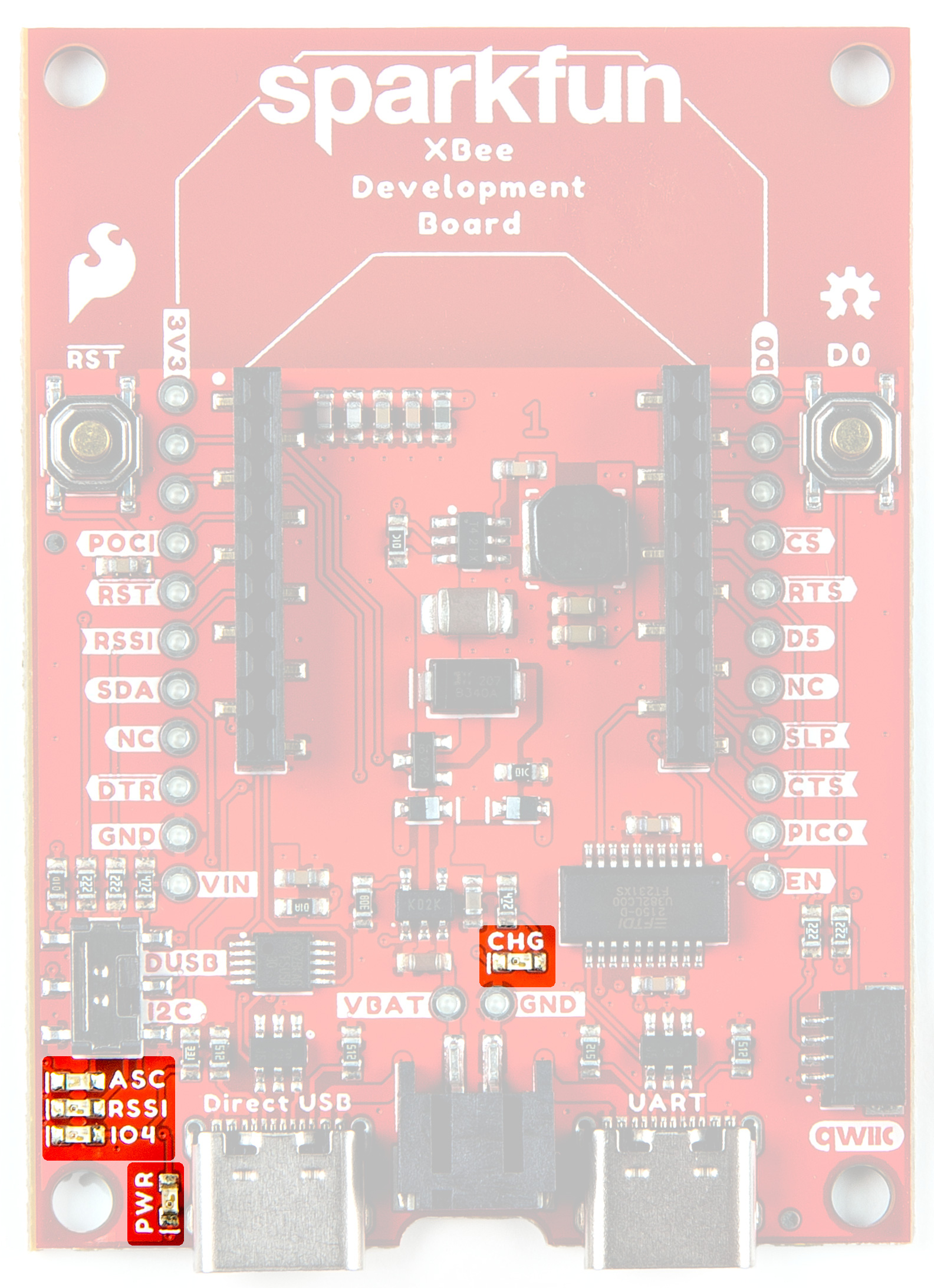
CHG
This LED lights up when the charge circuit is in use.
PWR
This LED lights up when power is provided to the board.
IO4
This Green LED is a user-defined LED connected to D4 of the XBee.
ASC
This LED on the development board blinks when the Digi XBee is registered to the cellular network.
| Blink | Timing | Meaning |
|---|---|---|
| On | Solid | Not joined to a mobile network |
| Double Blink | ½ second | The last TCP/UDP/SMS attempt failed. If the LED has this pattern, you may need to check DI (Remote Manager Indicator) or CI (Protocol/Connection Indication) for the cause of the error. |
| Single blink | 1 Second | Normal Operation |
RSSI
This LED is the Received Signal Strength Indicator. When configured, it reflects the received signal strength.
RSSI PWM The RSSI/PWM output is enabled continuously, unlike other Digi XBee products where the output is enabled for a short period of time after each received transmission. If running on the XBIB development board, DIO10 is connected to the RSSI LEDs, which may be interpreted as follows:
| PWM duty cycle | Number of LEDs turned on | Received signal strength (dBm) |
|---|---|---|
| 79.39% or more | 3 | 83 dBm or higher |
| 62.42% to 79.39% | 2 | -93 to -83 dBm |
| 45.45% to 62.42% | 1 | -103 to -93 dBm |
| Less than 45.45% | 0 | Less than -103 dBm, or no cellular network connection |
Jumpers
SHLD/SHLD1
For most applications, the single point grounding of the Direct USB or UART at the USB-C connector is sufficient. However, should you run into problems with EMI/EMC, we've provided jumpers that allow you to disconnect either connector from ground.
Cut the SHLD jumper for the UART USB-C; cut the SHLD1 jumper for Direct USB.
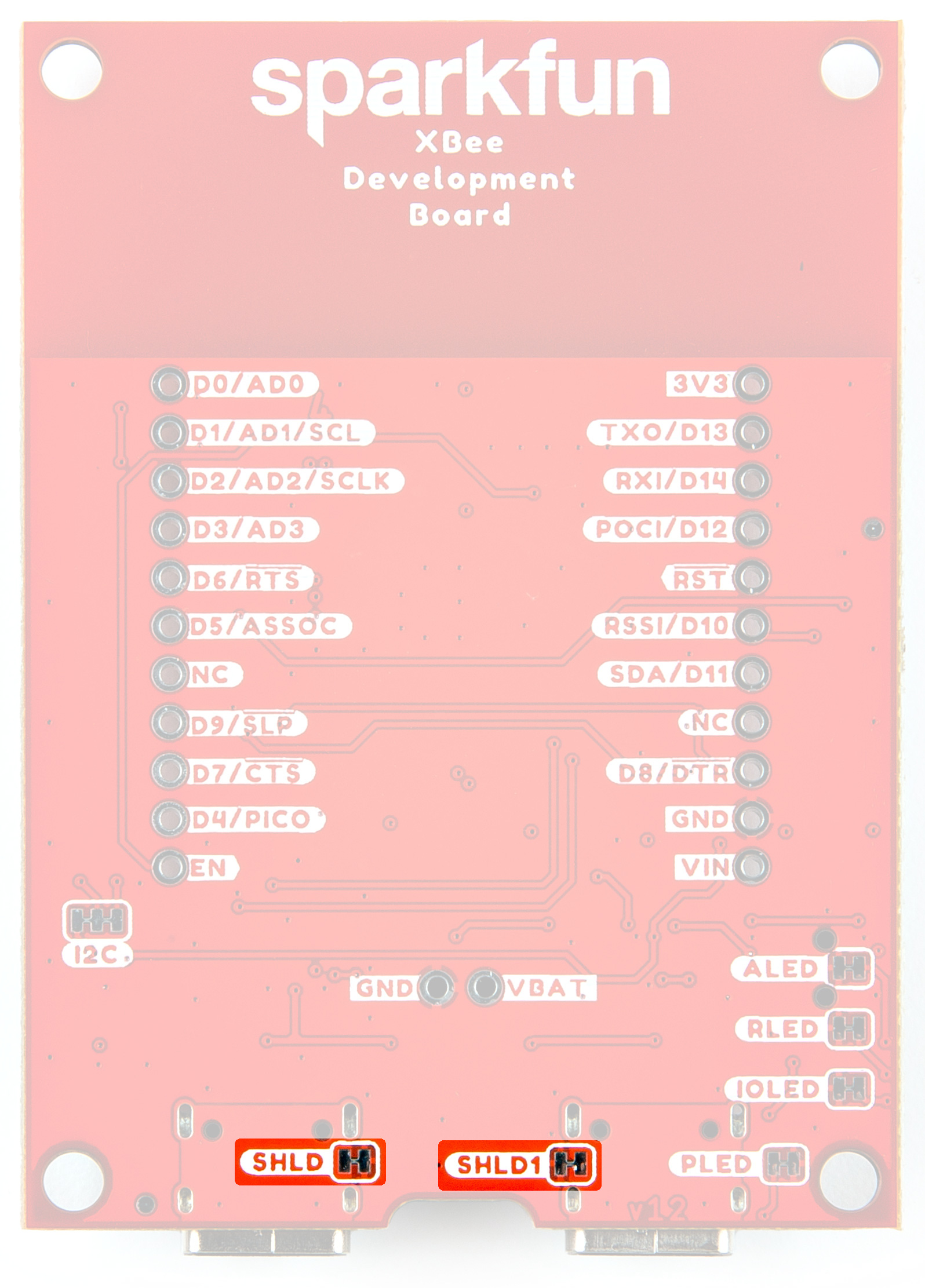
Shield Jumpers
ALED/PLED/RLED/IOLED
If power consumption is an issue (or if you just don't like the LEDs), cut the respective jumper to sever power to the LED.
- PLED: Red
- ALED: Blue
- RLED (RSSI): Yellow
- IOLED: Green
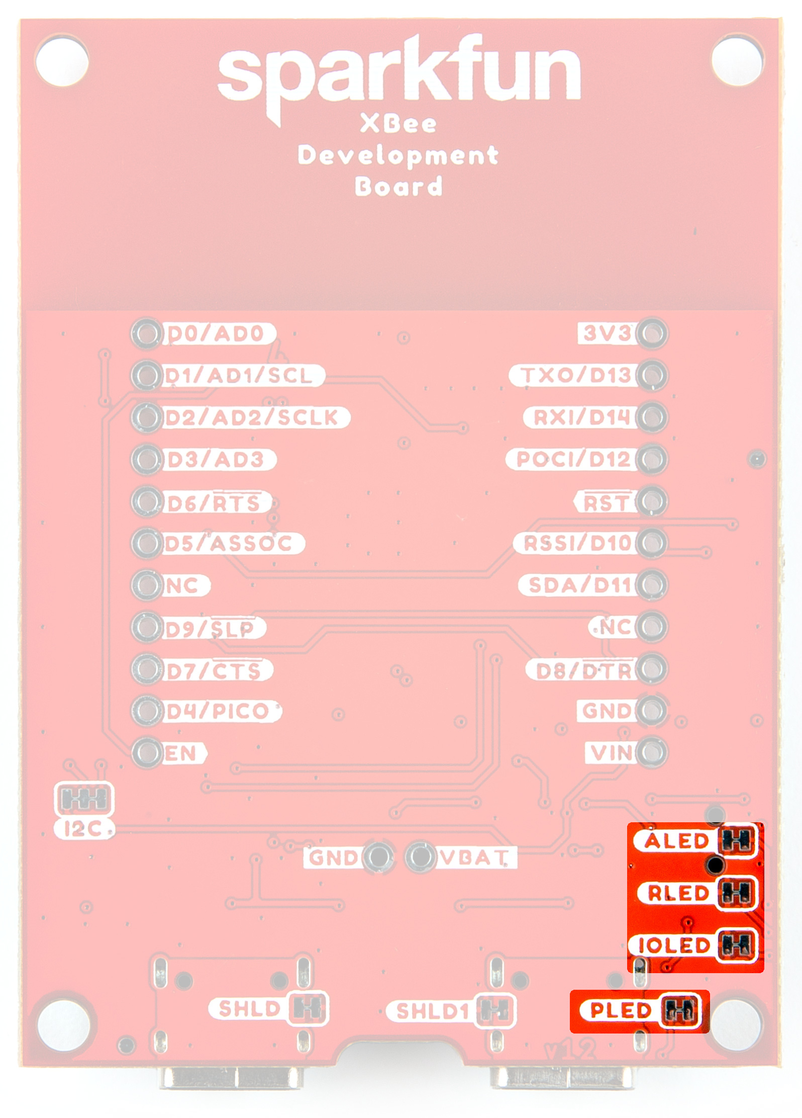
LED Jumpers
I2C
The I2C jumper pulls the SDA and SCL pins to VDD (normally 3.3V) through two 2.2K Ohm resistors. If you have multiple Qwiic devices on the same bus you may want to disable these by opening the jumper (assuming they are also operating at 3.3V logic).
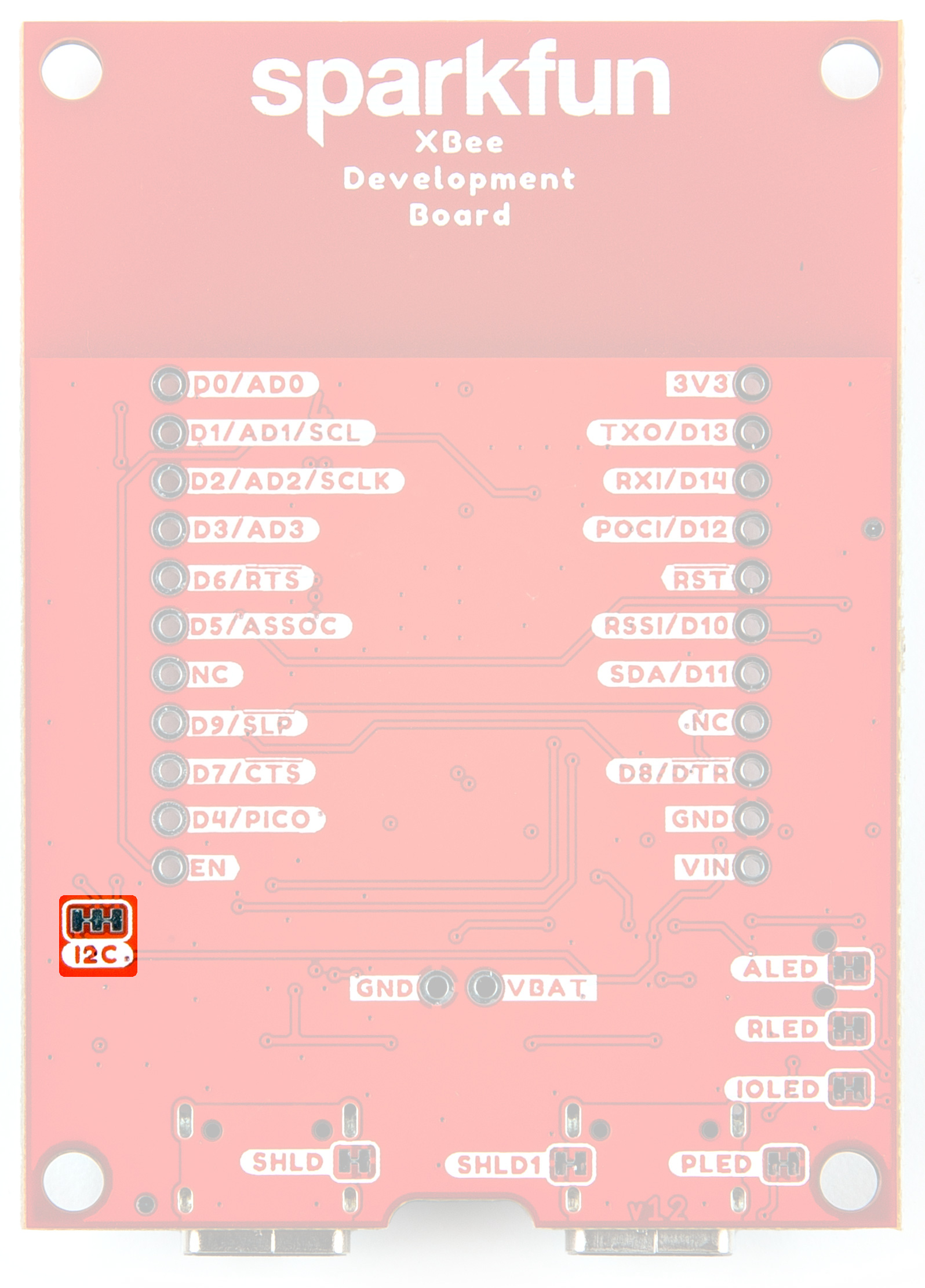
I2C Jumper
Board Outline
The overall size of the SparkFun Digi XBee® Development Board is 1.8" by 2.5". For specific measurements, see the image below.

Board Outline
Need more measurements?
For more information about the board's dimensions, users can download the Eagle files for the board. These files can be opened in Eagle and additional measurements can be made with the dimensions tool.
Eagle - Free Download!
Eagle is a CAD program for electronics that is free to use for hobbyists and students. However, it does require an account registration to utilize the software.
 Dimensions Tool
This video from Autodesk demonstrates how to utilize the dimensions tool in Eagle, to include additional measurements: