-
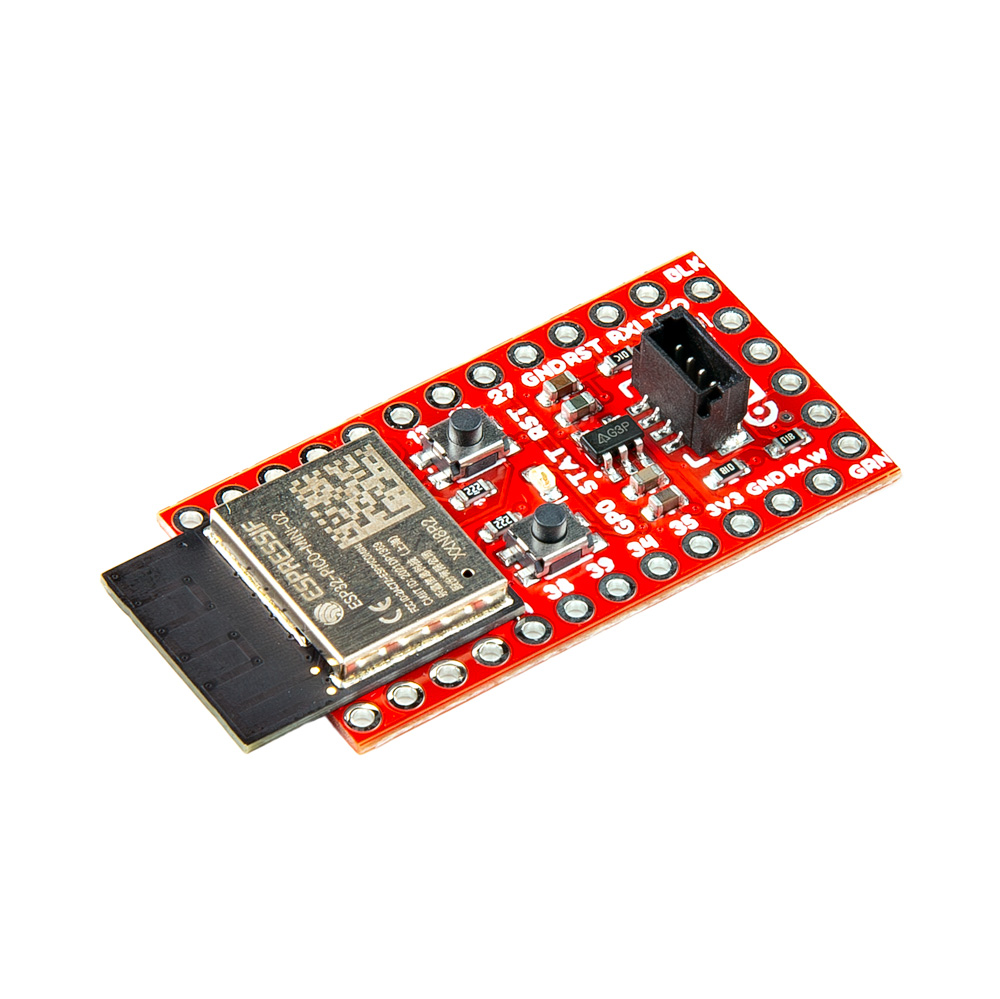
SparkFun ESP32 Qwiic Pro Mini
SKU: DEV-23386

-
The SparkFun ESP32 Qwiic Pro Mini houses the powerful ESP32-PICO-MINI-02-N8R2 variant from Espressif on our mini footprint. With two individually controllable CPU cores, adjustable CPU clock frequency, 8MB Flash, 2MB PSRAM, a co-processor that can be used in situations that require minimal computing power, as well as a rich set of peripherals such as capabilities for SD card interface, capacitive touch sensors, ADC, DAC, Two-Wire Automotive Interface, to Ethernet, high-speed SPI, UART, I²S, and I²C.
Purchase from SparkFun
Required Materials
To follow along with this tutorial, you will need the following materials. You may not need everything though depending on what you have. Add it to your cart, read through the guide, and adjust the cart as necessary.
 SparkFun ESP32 Qwiic Pro MiniDEV-23386 |
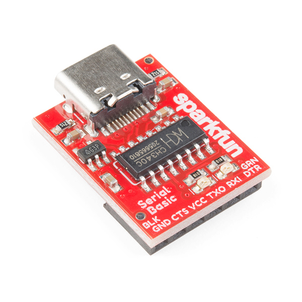 SparkFun Serial Basic Breakout - CH340C and USB-CDEV-15096 |
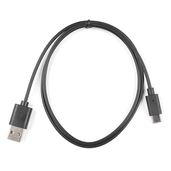
Reversible USB A to C Cable - 0.8mCAB-15425 |
Suggested Reading
As a more professionally oriented product, we will skip over the more fundamental tutorials (i.e. Ohm's Law and What is Electricity?). However, below are a few tutorials that may help users familiarize themselves with various aspects of the board.

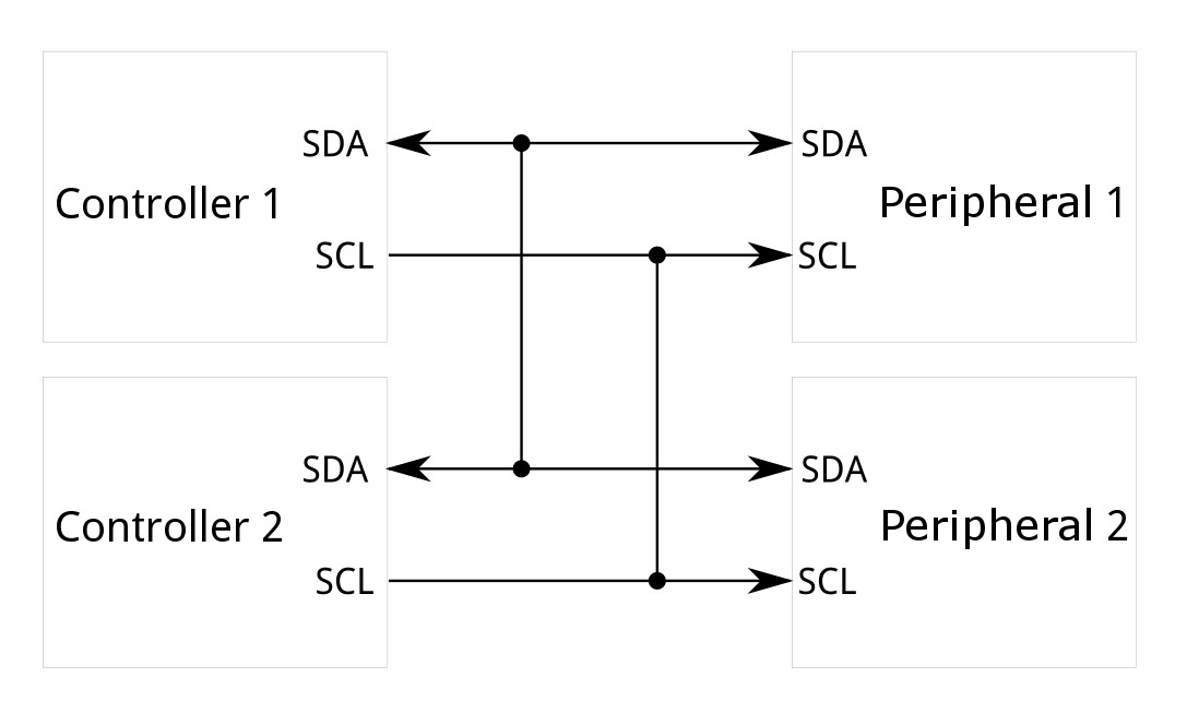

The SparkFun ESP32 Qwiic Pro Mini takes advantage of the Qwiic connect system. We recommend familiarizing yourself with the Logic Levels and I2C tutorials. Click on the banner above to learn more about Qwiic products.
Hardware Overview
ESP32 PICO Mini
At the core of the SparkFun ESP32 Qwiic Pro Mini is the ESP32-PICO-MINI-02-N8R2 variant which includes 8MB Flash and 2MB PSRAM. There are two CPU cores that can be individually controlled, and the CPU clock frequency is adjustable from 80 MHz to 240 MHz. The chip also has a low-power coprocessor that can be used instead of the CPU to save power while performing tasks that do not require much computing power, such as monitoring of peripherals. For more information, refer to the datasheet.

ESP32 PICO Mini
Power
Power is typically supplied via the VCC/GND pins using a USB to Serial adapter. Alternatively, external or portable power can be provided via the GND/RAW pins along the GPIO edge. Note: The AP2112K has a max input voltage of 6V.
The serial programming pins at the edge of the board are FTDI compatible and works best with our CH340 USB to Serial breakout. To utilize the GND/RAW pins along the GPIO edge, we recommend soldering the JST Right-Angle Connector - Through-Hole 2-Pin.

Serial Programming Pins

Power Plated Through Holes
Voltage Regulator - AP2112K
The AP2112K Voltage Regulator ensures that the appropriate voltage is provided to the various components of the board. The AP2112K has a max input voltage of 6V.

Voltage Regulator - AP2112K
Qwiic connector
The board includes a Qwiic Connector for use with our vast array of Qwiic sensors. The I2C data and clock lines are tied to 2.2kΩ pull-up resistors.
Note that we've mounted the Qwiic Connector vertically to prevent the occlusion of soldering and/or using the GPIO.

Qwiic connector
Buttons
There are two buttons on the board - Reset and Boot. The reset (RST) button allows users to reset the program running on the module without unplugging the board. The Boot Button allows the user to manually put the board into Bootloader Mode. To enter bootloader, hold the Boot button down when the ESP32 resets or powers on. These buttons are intentionally next to each other to make it a single finger rolling movement.

Buttons
LEDs
Two LEDs - Power(Red) and STAT(Blue) - show the user that power has been appropriately supplied to the board and the status of the data transfer.

Power and Status LEDs
GPIO
The PTH pins are compatible with older Pro Minis. There are a few analog input only pins. They are labeled clearly.

GPIO
Jumpers
Never modified a jumper before?
Check out our Jumper Pads and PCB Traces tutorial for a quick introduction!

Power Jumper
If you have concerns about power consumption, need to run dark, or really just don't like LEDs, you can cut this jumper to disable the red PWR LED on the front of the board.

Power Jumper
Board Dimensions
The board dimensions are illustrated in the drawing below; the listed measurements are in inches.

ESP32 Qwiic Pro Mini Board Dimensions
Need more measurements?
For more information about the board's dimensions, users can download the KiCad files for the board. These files can be opened in KiCad and additional measurements can be made with the dimensions tool.
KiCAD - Free Download!
KiCAD is a CAD program for electronics that is free to use for hobbyists and students. However, it does require an account registration to utilize the software.
Hardware Assembly
To program this board, and to use any of the I/O, you'll need to solder something to the board. In the least, we recommend soldering right-angle male headers or straight male headers onto the six-pin serial header. Either of these will interface easily with the SparkFun Serial Basic Breakout - CH340C and USB-C.
New to soldering?
If you have never soldered before or need a quick refresher, check out our How to Solder: Through-Hole Soldering guide.
-

How to Solder: Through-Hole Soldering

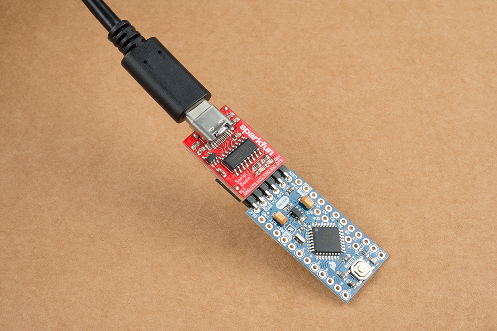
ESP32 Connected to Programming
Software Setup
With the ESP32 Qwiic Pro Mini Board connected to our computer, it's time to set up the boards package in Arduino.
Attention
If this is your first time using Arduino, please read through our tutorial on installing the Arduino IDE. If you have not installed an Arduino library before, we recommend you check out our installation guide.
Installing espressif Arduino Boards
Install the espressif ESP32 Arduino Boards package by opening the Boards Manager tab on the left side of the IDE, then search for "espressif ESP32" and install the latest version of the ESP32 boards package as the screenshot below shows. This assumes the use of Arduino 2.x. Legacy users (Arduino 1.8x and previous) can find the Boards Manager tool in File/Tools/Boards Manager.

Note: For more instructions, users can follow this tutorial on Installing Additional Cores provided by Arduino. Users will also need the .json file for the Espressif Arduino core:
Arduino Example
Now that we've installed the espressif boards package in Arduino, it's time to upload our first sketch to make sure everything is working properly.
Example - Blink
This basic example makes sure the board package installed correctly and the board accepts programming properly to blink the green STAT LED on the board every second. Open the example in Arduino by navigating to File > Examples > Basics > 01-Blink.
You will need to modify LED_BUILTIN to pin 0 like so:

Code changes for LED_BUILTIN
Make sure you have the board (ESP32 Dev Board) and select your applicable COM port:

Board and Port selected
Uploading Code
Attention
While most ESP32 boards include an auto-reset and auto-bootload circuitry, these have been removed from the ESP32 Pro Mini to save space. This means you will need to manually enter and exit the bootloader mode every time new code is to be loaded.
Before uploading, you'll need to put the board into the serial bootloader with the BOOT button. Holding down the BOOT button, while connecting the board to a computer through its USB-C connector or resetting the board will cause the MCU to enter the Firmware Download mode and its serial bootloader. The board will remain in this mode until it is power cycled by either pressing the RST button or the board is unplugged/plugged in.
- Hold the BOOT button down.
- Reset the MCU. This can be accomplished by:
- Plugging the board into a USB to Serial board.
- Or, press and releasing the RST button while holding BOOT.
- Release the BOOT button.
- After programming is completed, reboot the MCU.
- Press the RST button.
- Or, power cycle the board.
Once the board is in the serial bootloader, you can upload code through the Arduino interface. Once your code is uploaded, you will need to hit the RST button to get your sketch running.

Blink Example
Troubleshooting Tips
Note
Not working as expected and need help?
If you need technical assistance and more information on a product that is not working as you expected, we recommend heading on over to the SparkFun Technical Assistance page for some initial troubleshooting.
If you don't find what you need there, the SparkFun Forums are a great place to find and ask for help. If this is your first visit, you'll need to create a Forum Account to search product forums and post questions.
Resources:
For more resources related to the SparkFun ESP32 Qwiic Pro Mini, check out the links listed here:
- Product Page
- Schematic (PDF)
- KiCAD Files (ZIP)
- Board Dimensions (PDF)
- Hardware GitHub Respository