Software Setup
ESP32 Firmware
We have intentionally kept the ESP32 firmware as simple as possible - its only tasks are to: discipline the TCXO oscillator; control the OLED display. The intention is that you can easily develop your own firmware for the GNSSDO(+) if the SparkFun firmware does not meet your needs.
The /Firmware/Binaries folder contains the firmware binaries.
You can update or reload the firmware using the SparkFun RTK Firmware Uploader.
You can of course modify the hardware too, should you want to. The design is completely open-source.
Note
The mosaic-T module has numerous capabilities and a multitude of ways to configure and interface with them. Without regurgitating all the information that is documented in Septentrio's user manuals and videos, we have tried to highlight a good majority of the module's aspects.
With that said, please feel free to file an issue if you feel we have missed something that may benefit other users. (Don't forget to provide us with a link to the documentation and what section the information is located.)
mosaic-T
RxTools Software Suite
Tip
Even if you aren't necessarily interested in it, we highly recommend that users install the RXTools software suite before plugging in their board. For Windows PCs, it also includes the USB driver for the module that enables the Ethernet-over-USB support and virtual COM ports.
Users should install the RXTools software suite on their computer to interact with the mosaic-T module through the USB interface. The software package includes the USB-IP driver1 necessary to recognize the board as an ethernet device on Windows PCs (1).
- On Linux, the standard Linux CDC-ACM driver is suitable.
System Requirements2
- Windows 7
- Windows 8
- Windows 10
- Fedora 23 (or later) using Qt technology.
- The standalone tools (except
bin2asc) will run on older distributions.
- The standalone tools (except
The minimal hardware requirements (1Hz update3):
- CPU: 1 GHz processor
- RAM: 1 GB RAM
- Screen Resolution: 1024×768 or higher resolution
Installation Instructions2
Users can install RxTools software suite by running the installation executable4(1), located in the RxTools\windows directory of the downloaded *.zip file5. During the installation process, users will be notified if a previous version of RxTools is already installed then the previous version will be uninstalled. Next, users will need to provide an installation directory for the RxTools software suite. Users will then select which of the following applications6 are installed:
- For RxTools v22.1.0, the installation filename is
RxTools_22_1_0_Installer.exefor Windows PCs.
- RxControl
- SBF Converter
- SBF Analyzer
- RxLogger
- RxUpgrade
- RxDownload
- RxPlanner
- Data Link
- RxAssistant
- RxLauncher
Warning
It is recommended that users NOT install RxControl as root, for security reasons and to avoid installation overwrites of other system settings. To make RxTools available to more than one user, provide a shared installation directory.
Users can install RxTools software suite by running the installation binary4(1), located in the RxTools/linux-i386/ directory of the downloaded *.zip file5. During the installation, users will be prompted for an installation directory. If there are any previous installations of RxControl, please use a different directory to avoid conflicts.
- For RxTools v22.1.0, the installation filename is
RxTools_22_1_0_Installer.binfor Linux.
Permission Settings
Once installed, users may need to reconfigure their permission settings:
-
RxTools will need rights to access the
/dev/ttyS*serial ports.-
To access the serial ports, users must be part of the
uucpandlockgroups (1). This can be configured by editing the/etc/group7 file and adding the username to the lines defining theuucpgroup and thelockgroup.For example, when adding the user
jsmithto theuucpgroup, users would modify the/etc/groupfile as shown below: -
On Linux machine administered centrally on a local network, ask your system administrator to be included in the
uucpandlockgroups.
-
-
RxTools also needs read/write (
rw) access(4) to the/dev/ttyS*serial ports.-
Users can change the permissions with the
chmod8 command:
-
- On most Linux operating systems, the
/dev/ttyS*devices are owned byrootand belong to theuucpgroup with read/write (rw) access. Additionally, the devices are normally locked by writing a file in the/var/lock/directory, with the same permissions. - Remove
- Replace with this line
- By default, users will normally have read/write (
rw) access to the/dev/ttyS*serial ports. - where users must specify the port number
e.g./dev/ttyS0might be portCOM1
Note
In order for these changes to take effect, users must update their environment by logging out and back in.
Be aware that the X-session has to be restarted as well. On most systems, this can be done by pressing the key combination Ctrl + Alt + Backspace
64-bit OS
In order to run the RxTools on a 64-bit Linux operating system, users might have to install the 32-bit version of the C standard library.
- For Fedora installations, this is the
glibc.i686package. - The equivalent for Debian(/Ubuntu) installations is the
ia32-libspackage.
Septentrio USB Driver
If users haven't already installed the RxTools software suite on their Windows PC, they will need to install the USB driver1 necessary to recognize and interact with the mosaic-T module through the USB interface.
A Windows USB driver for the mosaic-T can be installed through two methods:
- RxTools Software Suite (1)
- mosaic-T GNSS Receiver Module (2)
- The driver is installed during the installation process.
- The installation file for the Windows USB driver will be available from the mass-storage device when the board is initially connected to the computer.
Once installed, the driver emulates two virtual serial ports, which can be accessed as standard COM ports to the receiver.
Terminal Emulators
Most terminal emulation programs will not make a distinction between virtual or native COM ports. However, for virtual serial ports, the port settings (i.e. baud rate, etc.) are not relevant and the default configuration is used in the terminal emulation program. However, the physical/native COM ports will have the following default setting:
- Baudrate: 115200bps
- Data Bits: 8
- Parity: No
- Stop Bits: 1
- Flow Control: None
Having Trouble?
For users who are having trouble installing the USB driver, we have an archived version (v3.0.29) of the installation file. Users can download version 3.0.2 of the driver, by clicking on the button below.
On Linux, the standard Linux CDC-ACM driver is suitable for the mosaic-T module.
Web Interface
With the USB driver installed, the mosaic-T module supports Ethernet-over-USB. The default IP address allocated for the Ethernet-over-USB interface is 192.168.3.1. This IP can be entered in any browser to open a connection to the receiver's Web Interface as shown below.

All the drop-down navigation tabs in the web interface.
Info
The default IP address cannot be changed; this feature is only to be used when a single receiver is connected to your computer.
Invalid IP Address (WiFi Only)
One of the documentation pages on Septentrio's website, specifies a default IP address of 192.168.20.1 for the web interface. However, that address is for a WiFi enabled product and cannot be used with this product.
ESP32
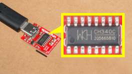
CH340 USB Driver
Users will need to install a USB driver for the CH340 serial-to-USB chip, in order to communicate with the ESP32 module. The latest USB drivers for the CH340 are available from the manufacturer, on the WCH website:
Need Directions?
For users having trouble installing the CH340 USB driver, check out our video and hookup guide:
-
How to Install CH340 Drivers
Terminal Emulator
In order to configure the firmware settings on the ESP32, users will need to install a serial terminal emulator on their computer.
For Windows computers, we highly recommend TeraTerm.
Some Linux operating systems will already have the screen terminal emulator preinstalled.
Need Directions?
Check out our hookup guide to install your favorite terminal emulator:
-
Serial Terminal Basics
Software Settings
When connected to the ESP32 CH340 COM port at 115200 baud, pressing any key in the terminal emulator will open the firmware Main Menu:

The ESP32 firmware main menu.
Configure Operation
Select option c ("c" followed by "Enter") to configure the firmware:

The ESP32 firmware configuration menu.
- 1) Minimum TCXO Warm Up (s)
- This defines the minimum oscillator warmp-up in state STATE_TCXO_WARMUP
- Default: 120s
- GNSSDO+ only
- 2) Required TCXO Temperature Stability (ADU)
- This defines the required temperature stability to exit STATE_TCXO_WARMUP
- Default: 0.01 ADU
- GNSSDO+ only
- 10) PI P term for initial frequency steering
- This defines the PI control loop Proportional term used during initial frequency locking
- The default value depends on the oscillator (GNSSDO vs. GNSSDO+)
- 11) PI I term for initial frequency steering
- This defines the PI control loop Integral term used during initial frequency locking
- The default value depends on the oscillator (GNSSDO vs. GNSSDO+)
- 12) Required bias stability for frequency lock
- The firmware will stay in state STATE_GNSS_FINETIME until the change in Bias reaches this
- Default: 1.0e-10
- 13) PI P term for fast ramping
- This defines the PI control loop Proportional term used during fast ramping (state STATE_GNSS_FREQUENCY_LOCK) to remove the large initial bias
- The default value depends on the oscillator (GNSSDO vs. GNSSDO+)
- 14) PI I term for fast ramping
- This defines the PI control loop Integral term used during fast ramping (state STATE_GNSS_FREQUENCY_LOCK) to remove the large initial bias
- The default value depends on the oscillator (GNSSDO vs. GNSSDO+)
- 15) TCXO steering ramp rate limit (s/s)
- This setting limits the maximum rate (change) in the setpoint during fast ramping
- The default value depends on the oscillator (GNSSDO vs. GNSSDO+) but is typically 250ns/s
- 16) TCXO steering ramp step size (s)
- This setting sets the rate of change of the setpoint during fast ramping
- The default value depends on the oscillator (GNSSDO vs. GNSSDO+) but is typically 0.5ns
- 17) TCXO steering ramp asymmetry
- If needed, this setting can be used to adjust the step size used during the 'down' ramp compared to the 'up'
- The default value is 1.0 = no asymmetry
- A value of 0.5 makes the 'down' ramp steps half the size of the 'up' ramp
- If 16) is set to 1.0ns, and 17) is set to 0.5, the 'down' ramp steps will be 0.5ns. The 'down' ramp will take twice as long as the 'up'
- If 16) is set to 1.0ns, and 17) is set to 2.0, the 'down' ramp steps will be 2.0ns. The 'down' ramp will take half the time of the 'up'
- 18) TCXO steering ramp minimum repeats
- This sets the minimum number of times state STATE_GNSS_FREQUENCY_LOCK is repeated
- The default value depends on the oscillator (GNSSDO vs. GNSSDO+)
- 19) Required bias for phase lock (s)
- The firmware will stay in state STATE_GNSS_FREQUENCY_LOCK if the Bias exceeds this after fast ramping
- Default: 100ns
- 20) PI P term for final TCXO disciplining
- This defines the Proportional term for the TCXO frequency PI control loop
- The default value depends on the oscillator (GNSSDO vs. GNSSDO+)
- 21) PI I term for final TCXO disciplining
- This defines the Integral term for the TCXO frequency PI control loop
- The default value depends on the oscillator (GNSSDO vs. GNSSDO+)
- 30) Prefer non-composite GPS bias - if available
- With a subscription to Fugro AtomiChron, this option allows the individual GPS clock bias to be preferred over the composite Fugro bias.
- You can enable a preference for either GPS or Galileo. Enabling GPS will disable Galileo.
- 31) Prefer non-composite Galileo bias - if available
- With a subscription to Fugro AtomiChron, this option allows the individual Galileo clock bias to be preferred over the composite Fugro bias.
- You can enable a preference for either GPS or Galileo. Enabling Galileo will disable GPS.
- 40) Pulse-Per-Second Interval
- This defines the interval of the PPS signal. The intervals are defined by the mosiac-T firmware. Use "40" and "Enter" to scroll through the intervals:
- "off"
- "msec10"
- "msec20"
- "msec50"
- "msec100"
- "msec200"
- "msec250"
- "msec500"
- "sec1"
- "sec2"
- "sec4"
- "sec5"
- "sec10"
- "sec30"
- "sec60"
- This defines the interval of the PPS signal. The intervals are defined by the mosiac-T firmware. Use "40" and "Enter" to scroll through the intervals:
- 41) Pulse-Per-Second Polarity
- This defines the PPS signal polarity: Low2High or High2Low
- 42) Pulse-Per-Second Delay (ns)
- This allows the timing of the PPS signal to be advanced or retarded. The units are nanoseconds
- On GNSSDO+:
- Advanced users may want to adjust this to ensure a slight mis-alignment between PPS and the 10MHz clock
- This would ensure their rising edges are slightly separated and that the 74LVC1G175 flip-flop (U15) produces a clean output
- Consult page 7 of the GNSSDO+ schematic for more details
- 43) Pulse-Per-Second Time Scale
- This defines which time scale is used to generate the PPS signal.
- "GPS"
- "Galileo"
- "BeiDou"
- "GLONASS"
- "UTC"
- "RxClock"
- This defines which time scale is used to generate the PPS signal.
- 44) Pulse-Per-Second Max Sync Age (s)
- This defines how long PPS pulses will be produced when the GNSS signal is lost or jammed: 0 to 3600 seconds
- 45) Pulse-Per-Second Pulse Width (ms)
- This defines the width of the PPS signal. The units are milliseconds: 0.000001 to 1000.000000
- 50) TCP Server (IPS1)
- See TCP Server (IPS1) below for more details
- 51) TCP Server Port
- The port for the TCP connection. Default is 28785
- 60) Save TCXO control word to TCXO memory
- This option allows the current TCXO control word to be saved manually to TCXO internal memory
- GNSSDO+ only
- This may be useful when setting up a new GNSSDO+. E.g. the control word could be saved manually when state STATE_GNSS_FINETIME is almost complete
- The control word will be saved automatically when the firmware has been in state STATE_GNSS_PHASE_LOCK for one hour
To reset all settings to their default values, select "r", "Enter", "y", "Enter"
The settings are saved to non-volatile memory (NVM, LittleFS) on exiting the menu. Ensure you fully exit the menu ("x", "Enter", "x", "Enter") to save any modified settings.
The TCXO frequency control word is saved to NVM once per hour, to allow a quicker startup at the next power-on.
TCP Server (IPS1)
When TCP Server (IPS1) is enabled, the ESP32 serial console is diverted from the CH340 USB (CONFIG ESP32) interface to the mosaic-T COM3 UART interface and daisy chained to the IPS1 TCP server. The configuration menu and debug messages can then be accessed over TCP / Telnet on the chosen port. The CH340 USB (CONFIG ESP32) interface is then no longer active.
TCP / Telnet is supported over both Ethernet and the Ethernet-over-USB connection. Only one TCP2Way connection is supported.
If you are using Tera Term:
- Select TCP/IP and Telnet
- Enter the mosaic-T's IP address in Host
- If you are connected via the CONFIG MOSAIC Ethernet-over-USB interface, the IP address is 192.168.3.1
- Enter the TCP Server Port number in TCP port#
- The default port is 28785

Tera Term configuration for TCP.
Debug Software
Select option d ("d" followed by "Enter") to configure the software debug options:

The ESP32 firmware debug menu.
The debug options are what we use at SparkFun to check that the firmware is running correctly. You should not need change any of the options, except perhaps option 8 Print conditions. This option controls the periodic CSV messages seen in the console when the menu is closed. The format can be changed to human-readable text, or the messages can be disabled if desired.
Print Conditions (periodic messages)
The format of the Print conditions CSV data is:
YYYY/MM/DD,HH:MM:SS,Epoch,Lat,Lon,Alt,TimeSys,Error,Fine,PPS,Bias,Drift,Source,TCXO,PkSteer,IkSteer,PkRamp,IkRamp,Pk,Ik,Press,Temp,Hum,TCXO_Temp,Mode,Temp_Smooth,Bias_Smooth,Rate,Rate_Held,Setpoint,Turn,Error,Repeat
- YYYY/MM/DD is the date from the ReceiverTime SBF message
- HH:MM:SS is the time from the ReceiverTime SBF message
- Epoch is the date and time in Unix epoch format: seconds.milliseconds from midnight UTC January 1st 1970. This is useful when plotting the data against time.
- Lat is the Latitude in degrees from the PVTGeodetic SBF message (7 decimal places)
- Lon is the Longitude in degrees from the PVTGeodetic SBF message (7 decimal places)
- Alt is the Altitude in metres from the PVTGeodetic SBF message (0.1mm resolution)
- TimeSys is the named TimeSystem from the PVTGeodetic SBF message
- Error is the Error byte from the PVTGeodetic SBF message. 0 indicates no error
- Fine is the FINETIME bit from the SyncLevel byte from the ReceiverTime SBF message
- PPS indicates if the Pulse-Per-Second output is enabled
- PPS is enabled when the RxClkBias reaches the required accuracy, set by RX Clock Bias Lock Limit
- Bias is the receiver clock bias in seconds
- Drift is the receiver clock drift in PPM
- Source is the source of the receiver clock bias reported in Bias
- By default, this is PVT indicating the source is the composite RxClkBias from the PVTGeodetic SBF message
- If AtomiChron is enabled and if Prefer non-composite GPS bias or Prefer non-composite Galileo bias has been selected, this will change to GPS or Galileo indicating that the individual non-composite bias from the FugroTimeOffset SBF message is available and is being used
- TCXO is the frequency control word written to the temperature-controlled oscillator
- PkSteer is the PI control loop Proportional term used during initial frequency locking - set in the configuration menu
- IkSteer is the PI control loop Integral term used during initial frequency locking - set in the configuration menu
- PkRamp is the PI control loop Proportional term during fast ramping to remove the large initial bias - set in the configuration menu
- IkRamp is the PI control loop Integral term during fast ramping to remove the large initial bias - set in the configuration menu
- Pk is the PI control loop Proportional term for the main Phase-Locked Loop - set in the configuration menu
- Ik is the PI control loop Integral term for the main Phase-Locked Loop - set in the configuration menu
- Press is the atmospheric pressure in hPa (mbar) : GNSSDO Plus (GNSSDO+) only
- Temp is the internal temperature in degrees C : GNSSDO Plus (GNSSDO+) only
- Hum is the relative humidity in %RH : GNSSDO Plus (GNSSDO+) only
- TCXO_Temp is the temperature-controlled oscillator internal temperature in ADU : GNSSDO Plus (GNSSDO+) only
- Mode is the firmware mode / state. Possible values are:
- NOT_CONFIGURED
- CONFIGURED
- ERROR_BEFORE_FINETIME
- WARMUP
- ERROR_DURING_WARMUP
- FINETIME
- ERROR_AFTER_FINETIME
- FREQUENCY_LOCK
- ERROR_AFTER_FREQUENCY_LOCK
- PHASE_LOCK
- ERROR_AFTER_PHASE_LOCK
- Temp_Smooth is the exponentially smoothed TCXO_Temp : state STATE_TCXO_WARMUP only : GNSSDO Plus (GNSSDO+) only
- Bias_Smooth is the exponentially smoothed change in Bias : state STATE_GNSS_FINETIME only
- Rate is the ramp rate (s/s) during state STATE_GNSS_FREQUENCY_LOCK
- Rate_Held is the capped ramp rate (s/s) during state STATE_GNSS_FREQUENCY_LOCK
- Setpoint is the Bias target value which during ramping in state STATE_GNSS_FREQUENCY_LOCK
- Turn is the turn-around point in state STATE_GNSS_FREQUENCY_LOCK, from the 'up' ramp to the 'down' ramp
- Error is the error term (difference between the Setpoint and the Bias) in state STATE_GNSS_FREQUENCY_LOCK
- Repeat is the count of the number of times state STATE_GNSS_FREQUENCY_LOCK has been repeated
Note
The GNSSDO Plus (GNSSDO+) contains a MS8607 pressure, temperature and humidity sensor. The readings are reported in the periodic messages as Press, Temp and Hum.
The temperature reading will be higher than expected due to the sensor's proximity to the OCXO. The OCXO runs at elevated temperature; heat will be coupled to the sensor by convection, radiation and conduction (through the PCB).
Firmware Upgrade
The /Firmware/Binaries folder contains the firmware binaries. v3.0 is the latest stable release - as at 4-13-26.
You can update or reload the firmware using the SparkFun RTK Firmware Uploader.
See below for details on how to upload with esptool from the command line.
Compiling Firmware - using Docker
To compile the GNSSDO Firmware, you need to use the correct version of the ESP32 Arduino core and of each required Arduino library. It is tedious and error-prone. Especially on Windows. We've lost count of the number of times code compilation fails on our local machines, because we had the wrong ESP32 core installed... It is much easier to sandbox the firmware compilation using an environment like Docker.
Docker is open-source. It is our new favourite thing!
Here is a step-by-step guide for how to install Docker and compile the firmware from scratch:
Clone, fork or download the GNSSDO repo
To build the GNSSDO Firmware, you obviously need a copy of the source code.
Click on the icon below to download a copy of the main (released) branch:

For the real Wild West experience, you can also download a copy of the release_candidate code branch. This is where the team is actively changing and testing the code, before it becomes a full release. The code there will usually compile and will usually work, but we don't guarantee it! We may be part way through implementing some breaking changes at the time of your download...
Install Docker Desktop
- (Optional) Head to Docker and create an account. A free "Personal" account will cover occasional compilations of the firmware
- Download and install Docker Desktop - there are versions for Mac, Windows and Linux. You may need to restart to complete the installation.
- Run the Desktop
- You don't need to have an account and you don't need to be signed in
- You only need to be signed in if you want to store or share your Container on Docker Hub
- If you don't sign in, Docker Desktop will run in Personal mode - which will cover local compilations of the firmware
- On Windows, you may see an error saying "WSL needs updating Your version of Windows Subsystem for Linux (WSL) is too old". If you do:
- Open a command prompt
- Type
wsl --updateto update WSL. At the time of writing, this installs Windows Subsystem for Linux 2.6.1 - Restart the Docker Desktop
- If you are using Docker for the first time, the "What is a container?" and "How do I run a container?" demos are useful - but not essential
- On Windows, you may want to give Docker Desktop permission to access to your Network, so it can access (e.g.) HTML ports
- You can Stop the container and Delete it when you are done
- You may want to prevent Docker from running when your machine starts up
- Uncheck "Start Docker Desktop when you sign in to your computer" in the Desktop settings
Using Docker to create the firmware binary
- Make sure you have Docker Desktop running. You don't need to be signed in, but it needs to be running.
- Open a Command Prompt and
cdinto the SparkFun_GNSSDO folder - Check you are in the right place. Type
dirand hit enter. You should see the following files and folders:
cd Firmwareand thendiragain. You should see:
-
The file that does most of the work is the
Dockerfile -
Run
compile_with_docker.batto compile the firmware. It does everything for you -
Type
diragain. Hey presto! You have your newly compiled firmware binary!
You can then use (e.g.) the SparkFun RTK Firmware Uploader to upload the binary onto the ESP32.
You may find the .elf file useful if you are trying to debug the code with me-no-dev's Exception Decoder.
Uploading Firmware - using esptool
The SparkFun RTK Firmware Uploader contains a copy of Espressif's esptool. It is esptool that actually performs the code upload.
If you want to upload new firmware manually from the command line, here are the commands:
esptool.py --chip esp32 --port /dev/ttyUSB0 --baud 460800 --before default_reset --after no_reset write_flash -z --flash_mode dio --flash_freq 80m --flash_size detect 0x1000 RTK_Surveyor.ino.bootloader.bin 0x8000 RTK_Surveyor_Partitions_16MB.bin 0xe000 boot_app0.bin 0x10000 GNSSDO_Firmware.ino.bin
followed by:
On Windows, you can replace esptool.py with esptool.exe. You can find a copy of esptool.exe in the Utils folder.
On Windows, replace /dev/ttyUSB0 with the name of your CH340 COM port: COM1 or similar.
You can find copies of RTK_Surveyor.ino.bootloader.bin, RTK_Surveyor_Partitions_16MB.bin and boot_app0.bin in the Firmware Uploader resource folder.
Enjoy!
- Your friends at SparkFun
-
On Linux, the standard Linux CDC-ACM driver is suitable. ↩↩↩
-
The system requirements and installation instructions are from the RxTools v22.1.0 user manual. This information may change in later iterations of the software suite. Please refer to the user manual (of the version you are utilizing) for the most accurate information. ↩↩
-
Higher data rates will require higher CPU speed and more memory capacity. ↩
-
Users will need administrative privileges to install the RxTools software. ↩↩
-
Users may need to extract the RxTools installation files from the downloaded, compressed file. ↩↩
-
Please see the release notes for the issues and limitations of the RxTools applications. ↩
-
Requires c privileges. ↩
-
Changing these permissions also requires
rootprivileges. ↩ -
For the latest USB driver from Septentrio, please install their driver through the RxTools software suite.
This driver version was archived at the time that the mosaic-T hookup guide was written. Please do not request for the file to be updated. ↩