Hardware Assembly
USB Programming (UART1)
The USB connection can be utilized for serial communication and configuring the LG580P GNSS module. Users only need to connect their Quad-band GNSS RTK breakout board to a computer, using a USB-C cable.

The Quad-band GNSS RTK breakout board with USB-C cable being attached.
GNSS Antenna
In order to receive GNSS signals, users will need to connect compatible antennas. For the best performance, we recommend users choose active, multi-band GNSS antennas and utilize a low-loss cables.
Antenna Specifications
- Passive antennas are not recommended for the LG580P GNSS module.
- To mitigate the impact of out-of-band signals, utilize an active antenna whose SAW filter is placed in front of the LNA in the internal framework.
- DO NOT select and antenna with the LNA placed in the front.
- There is no need to inject an external DC voltage into the SMA connector for the GNSS antenna. Power is already provided from the LG580P module for the LNA of an active antenna.
Tip
For the best performance, we recommend users choose compatible L1/L2/L5/L6/L-Band GNSS antennas and utilize a low-loss cables. Also, don't forget that GNSS signals are fairly weak and can't penetrate buildings or dense vegetation. The GNSS antennas should have an unobstructed view of the sky.
Primary Antenna
The Antenna-1 SMA connector functions as the primary GNSS antenna connection for the LG580P GNSS receiver. The GNSS antenna on this connection will also function as the reference position for any heading computations.

A GNSS antenna attached to the SMA connector on the Quad-band GNSS RTK breakout board.
Secondary Antenna
The Antenna-2 SMA connector is only utilized for attitude determination by the LG580P GNSS receiver. With a minimum distance of 1m between the antennas and the base length setting configured, users should be able to achieve a heading accuracy of 0.1°.

Two GNSS antennas attached to the SMA connectors on the Quad-band GNSS RTK breakout board.
JST Connector (UART3)
The JST connector on the Quad-band GNSS RTK board, breaks out the UART3 port of the LG580P GNSS module. In certain circumstances, users may need to utilize the JST connector to transmit or receive RTK correction data with one of our radios.

The Telemetry Radio v3 connected to the Quad-band GNSS RTK breakout.
When connecting the Quad-band GNSS RTK breakout board to other products, users should be aware of the pin connections between the devices. The table below, details the pin connections of the locking JST connector on the Quad-band GNSS RTK breakout board.
| Pin Number |
1 (Left Side) |
2 | 3 | 4 |
|---|---|---|---|---|
| Label | VCC | TX3 | RX3 | GND |
| Function |
Voltage Output - Default: 3.3V - 3.3V or 5V |
UART3 - Receive |
UART3 - Transmit |
Ground |
Radio Transceivers
We have designed the locking JST connector to be plug-n-play with the following devices and cables. However, for the SiK Telemetry Radio v3, users should modify the VSEL jumper (1) on the back of the board to enable a 5V output on the VCC pin. Below, is a table summarizing the pin connections of the radios.
- While the SiK Telemetry Radio v3 may function with a 3.3V input, their specifications stipulate that a 5V power supply be provided.
| Pin Number |
1 (Left Side) |
2 | 3 | 4 | 5 |
6 (Right) |
|---|---|---|---|---|---|---|
| Label | 5V |
RX - SiK RXI - LoRaSerial |
TX - SiK TXO - LoRaSerial |
CTS | RTS | GND |
| Function |
Voltage Input - SiK: 5V - LoRaSerial: 3.3 to 5V |
UART - Receive | UART - Transmit |
Flow Control Clear-to-Send |
Flow Control Ready-to-Send |
Ground |
Radio Pin Connections
As documented in the LoRaSerial product manual, the pin connections between a host system (i.e. Quad-band GNSS RTK breakout board) and the LoRaSerial radio is outlined in the image below.
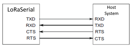
However, the flow control pins (CTS and RTS) are not available on the Quad-band GNSS RTK breakout board. Therefore, when connecting either of the radios, the pin connections should follow the table below:
| Board | RX | TX | GND |
|---|---|---|---|
| Radio | TX | RX | GND |
Radio Transceivers and Cables
Default Baud Rate
The baud rate for these radios are configured by the SERIAL_SPEED parameter. The default configuration is SERIAL_SPEED: 57600bps.
-

SiK Telemetry Radio V3 - 915MHz, 100mW
WRL-19032 -

SparkFun LoRaSerial Kit - 915MHz (Enclosed)
WRL-20029 -

JST-GHR-04V to JST-GHR-06V Cable - 1.25mm pitch
CAB-17239 -

GHR-04V-S to GHR-06V-S Cable - 100mm
CAB-17854
Breakout Pins
The PTH pins on the Quad-band GNSS RTK board are broken out into 0.1"-spaced pins on the outer edges of the board.
New to soldering?
If you have never soldered before or need a quick refresher, check out our How to Solder: Through-Hole Soldering guide.
-

How to Solder: Through-Hole Soldering
Headers
When selecting headers, be sure you are aware of the functionality you require.

Soldering headers to the Quad-band GNSS RTK breakout board.
Hookup Wires
For a more permanent connection, users can solder wires directly to the board.

Soldering wires to the Quad-band GNSS RTK breakout board.
BlueSMiRF Header (UART2)
The BlueSMiRF header pins on the Quad-band GNSS RTK board, breaks out the UART2 port of the LG580P GNSS module. This pin layout is perfect for connecting a serial-to-UART adapter or a transceiver for serial data, such as the BlueSMiRF Bluetooth™ serial-link.

Soldering male header pins to the Quad-band GNSS RTK breakout board.

Soldering female header pins to the Quad-band GNSS RTK breakout board.

Soldering female header pins to the back of the Quad-band GNSS RTK breakout board.
Jumper Access
When soldering a header to the back of the board, be aware that you'll loose access to the jumper in that area.

BT-VCC jumper.
Default Baud Rate
The baud rate for the BlueSMiRF transceiver is configured by the SerialSpeed parameter. The default configuration is SerialSpeed: 115200bps.
Connecting a BlueSMiRF transceiver to a female header that was soldered to the Quad-band GNSS RTK breakout board. This will allow users to pair their board with a mobile device; and log PNT data on the mobile device and/or connect the LG580P to an NTRIP server for RTK corrections (through mobile device's cellular or WiFi connection).


Connecting a UART adapter (Serial Basic) to a male header that was soldered to the Quad-band GNSS RTK breakout board. This will allow users to configure the LG580P, when the USB connection is unavailable.

