AT Commands
LoRaSerial radios are very flexible. By default, the radio is looking for serial communication at 57600bps. Open the terminal of your choice and enter +++ and wait for an OK. The radio is now ready for an AT command.
A PDF of all AT commands is available here.
Below is a brief list of commands:
| AT Command | Command Description |
|---|---|
| +++ | Enter command mode |
| AT | Reports OK |
| AT? | Display help text |
| ATB | Break the link |
| ATD | Display the debug settings |
| ATF | Restore factory settings |
| ATG | Generate new netID and encryption key |
| ATI | Display the radio version |
| ATI? | Display the information commands |
| ATIn | Display system information |
| ATO | Exit command mode |
| ATP | Display probe trigger settings |
| ATR | Display radio settings |
| ATS | Display the serial settings |
| ATT | Enter training mode |
| ATW | Save current settings to NVM |
| ATZ | Reboot the radio |
| AT-Param=xxx | Set parameter's value to xxx by name (Param) |
| AT-Param? | Print parameter's current value by name (Param) |
| AT-? | Display the setting values |
Table of AT Commands
The commands are best discussed in groups:
- Radio Commands
- Serial Commands
- Info Commands
- Debug Commands
A parameter is set using the AT- prefix, followed by the name of the command with an equals sign and the value to set. For example, sending AT-Echo=1** will enable serial echo. This setting can be stored in NVM (non-volatile memory) by sending the ATW command. To query a setting, send the AT command without a value and the device will respond with the current value. For example, sending AT-FrequencyMax will generate the response 928.000 followed by OK.
Radio Commands
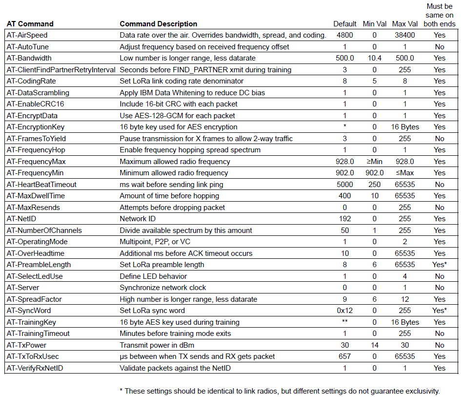
Table of common radio link parameters
A table of the subset of the common Radio Link Parameters is available here in PDF format.
Note: Some settings must be identical on both radios for the link to be possible. These settings are used to generate the unique hop table. If settings are not compatible between radios, they will not be able to communicate.
| AT Command | Command Description |
|---|---|
| AT-AirSpeed | Data rate over the air. Overrides bandwidth, spread, and coding. |
| AT-AutoTune | Adjust frequency based on received frequency offset |
| AT-Bandwidth | Low number is longer range, less data rate |
| AT-ClientFindPartnerRetryInterval | Seconds before FIND_PARTNER xmit during training |
| AT-CodingRate | Set LoRa link coding rate denominator |
| AT-DataScrambling | Apply IBM Data Whitening to reduce DC bias |
| AT-EnableCRC16 | Include 16-bit CRC with each packet |
| AT-EncryptData | Use AES-128-GCM for each packet |
| AT-EncryptionKey | 16 byte key used for AES encryption |
| AT-FramesToYield | Pause transmission for X frames to allow 2-way traffic |
| AT-FrequencyHop | Enable frequency hopping spread spectrum |
| AT-FrequencyMax | Maximum allowed radio frequency |
| AT-FrequencyMin | Minimum allowed radio frequency |
| AT-HeartBeatTimeout | ms wait before sending link ping |
| AT-MaxDwellTime | Amount of time before hopping |
| AT-MaxResends | Attempts before dropping packet |
| AT-NetID | Network ID |
| AT-NumberOfChannels | Divide available spectrum by this amount |
| AT-OperatingMode | Multipoint or P2P |
| AT-OverHeadtime | Additional ms before ACK timeout occurs |
| AT-PreambleLength | Set LoRa preamble length |
| AT-SelectLedUse | Define LED behavior |
| AT-Server | Synchronize network clock |
| AT-SpreadFactor | High number is longer range, less data rate |
| AT-SyncWord | Set LoRa sync word |
| AT-TrainingKey | 16 byte AES key used during training |
| AT-TrainingTimeout | Minutes before training mode exits |
| AT-TxPower | Transmit power in dBm |
| AT-TxToRxUsec | μs between when TX sends and RX gets packet |
| AT-VerifyRxNetID | Validate packets against the NetID |
Table of Radio Commands
-
AirSpeed - This is the effective rate in bits-per-second at which data is sent over the air. In general, the lower the airspeed, the greater the transmission distance. LoRaSerial uses buffers to receive and send serial over USB or UART at the SerialSpeed and begins sending that data in chunks over the air at the AirSpeed. The AirSpeed setting does not have to match the SerialSpeed. It is recommended to limit the total incoming data to match the airspeed. For example, regularly sending a group of 300 bytes with an air speed of 4800 bps (480 bytes per second) will allow the radio sufficient bandwidth. Sending 1,000 bytes per second with an air speed of 4800 bps (480 bytes per second) will within a few seconds overwhelm the link leading to buffer overflow and data loss. The default is 4800bps. Allowed values are 400, 1200, 2400, 4800, 9600, and 19200 bits per second. Changing the AirSpeed value overwrites the following 5 parameters:
-
HeartbeatTimeout
- RadioBandwidth
- RadioCodingRate
- RadioSpreadFactor
- TxToRxUsec
After AirSpeed is set, it is possible to modify any of the above five parameters. Note that AirSpeed is just an easy way to set the five parameters to known values. AirSpeed is not a parameter that is transmitted during training, merely a convenient way to set the five parameters in one step.
Note: The AirSpeed setting can be queried, but it is not back calculated. Said differently, after a system reset, the AirSpeed setting will report 0. This is because calculating the equivalent airspeed based on the user's settings results in non-sensical values that do not map cleanly with the defined AirSpeed options. Currently, the way to verify the device is set to the correct airspeed is to check the 5 parameters shown above against the settings shown on the AirSpeed calculation page.
-
AutoTune - Enabling autotune will cause the radio to tune the receiver frequency based on the calculated frequency error. This is used for testing and is not recommended for general use.
-
Bandwidth - The bandwidth used around a given frequency during LoRa transmissions. This setting is in kHz. This setting is overwritten if the AirSpeed setting is changed. It is recommended to use the airspeed setting unless you are very aware of the consequences. In general, a lower bandwidth number provides a longer range, but a lower overall data rate. Allowed bandwidths: 10.4, 15.6, 20.8, 31.25, 41.7, 62.5, 125.0, 250.0, and 500.0kHz.
-
ClientFindPartnerRetryInterval - In training mode, the client will transmit a special packet and then await a response from a server. This is the number of seconds between re-transmits of the FIND_PARTNER packet.
-
CodingRate - The coding rate used during LoRa transmissions. It is recommended to use the airspeed setting unless you are very aware of the consequences. This setting is overwritten if the AirSpeed setting is changed. In general, a higher spread factor provides a longer range, but a lower overall data rate. Allowed spread factors: 6 to 12 (inclusive).
-
DataScrambling - Enabling data scrambling will send all packets through an IBM data whitening process. This removes long sets of 1s or 0s from the packet to reduce DC bias during transmission. This is generally not needed and is not recommended when AES encryption is enabled. By default, scrambling is turned off.
-
EnableCRC16 - When CRC is enabled, any packet that does not have a valid CRC will be ignored. The SX1276 IC has CRC at the radio interface, but because of RF noise, the number of corrupt packets is noticeable. This extra layer ensures packet delivery. Enabling CRC will add two bytes to each frame.
-
EncryptData - By default, all packets are encrypted using 128-bit AES GCM. Disabling this will not achieve a greater range or bandwidth. Disabling encryption will allow all packets to be seen in clear text via an SDR or other monitoring device.
-
EncryptionKey - This is the 16-byte key used for AES encryption. While SparkFun provides a default value, it is strongly recommended to change this value for your own networks. This can be changed via command or via the P2P training method. Please see P2P Training for more information.
-
FramesToYield - During large data flows the receiving radio can request a yield within the ACK packet. When the transmitter receives a yield request, data flow is paused for FramesToYield * Frame Transmit Time. This gives the receiver a chance to transmit its own data allowing data to flow in both directions on the link.
-
FrequencyHop - The LoRaSerial implements frequency hopping spread spectrum (FHSS) by default to meet FCC Part 15.247 compliance. Turning off frequency hopping is not recommended unless You Know What You’re Doing™.
-
FrequencyMin/FrequencyMax - These are the lower and upper bounds for the allowed transmission frequencies in megahertz. By default, this is 902.0 to 928.0.
-
HeartbeatTimeout - Heartbeats are transmitted on a regular basis by the server and in point-to-point mode by the clients. This parameter specifies the time in milliseconds during which a HEARTBEAT frame should be transmitted. If a HEARTBEAT frame is not received within three (3) times this interval then the point-to-point link is broken. The default heartbeatTimeout is 5000 milliseconds (5 seconds).
-
MaxDwellTime - The number of milliseconds of transmission allowed on a given frequency before hopping intra-packet. The default is 400ms to be compliant with FCC Part 15.247. This means the radio will change its frequency to the next channel in the hop table during the packet transmission. Note this is the maximum dwell time; depending on the air speed setting the radio may have a hopping period that is shorter than the dwell time.
-
MaxResends - Number of retransmission attempts when an ACK is not received from the destination radio. The valid range is 0 to 255. The default of zero represents infinite and retries will continue as long as the two radios are receiving HEARTBEAT frames from each other. The transmission will fail only when the link breaks due to not receiving HEARTBEAT frames.
-
NetID - When VerifyRxNetID is enabled, each received packet is checked against the radio's network ID. If a packet is received with a non-matching NetID it is discarded. Changing the NetID is a handy way to make sure your radios do not interfere with other radios in the same vicinity.
-
NumberOfChannels - The available spectrum (default is 902MHz to 928MHz) is divided by this number of channels to create the channel spacing and allowed frequency list (aka the ‘hop table’). The default is 50 channels to meet FCC Part 15.247 compliance and may be changed to meet local regulations.
-
OperatingMode - The radios can operate in one of two different modes: Multipoint and Point-To-Point. See Operating Modes for more information.
-
MODE_MULTIPOINT (0) - A single server with multiple clients. All radios may broadcast to all other radios, but data is not guaranteed to be received by the other radios. This mode is great when real-time transmission is necessary and the application can tolerate some loss of data.
-
MODE_POINT_TO_POINT (1, default) - Communications between two LoRaSerial radios with guaranteed delivery of frames or the link breaks.
-
OverheadTime - The number of milliseconds to add to ACK and datagram times before ACK timeout occurs. The default is 10 milliseconds.
-
PreambleLength - The number of sync words to send at the start of a packet. Note that two LoRa radios with the same settings but different preamble lengths have been shown to intermittently receive packets from each other. Therefore, using a unique preamble length does not guarantee exclusivity. Allowed values: 6 to 65535.
-
SelectLedUse - Select how to display information on the LEDs. See LED States for more information.
-
Server - Enable (1) or disable (0) the server mode for training and for multipoint operation. The default is client mode (0). The radio designated as Server synchronizes the network. A server is required for Multipoint and Training modes.
-
SpreadFactor - The spread factor used during LoRa transmissions. It is recommended to use the airspeed setting unless you are very aware of the consequences. This setting is overwritten if the AirSpeed setting is changed. In general, a higher spread factor provides a longer range, but a lower overall data rate. Allowed spread factors: 6 to 12 (inclusive).
-
SyncWord - The byte used to synchronize LoRa transmissions. In general, this is set to 0x12 for non-LoRaWAN networks. Note that two LoRa radios with the same settings but different sync words have been shown to intermittently receive packets from each other. Therefore, using a unique synch word does not guarantee exclusivity. Allowed values: 0 to 255.
-
TxPower - The LoRaSerial uses a high-power 1W transceiver. By default, all transmissions are sent at the highest possible power of 30dBm which is compliant with FCC Part 15.247 when used with an antenna that has a gain of 6dBi or less. If your local regulations require lower transmission power this setting can be lowered. Allowed values are 30 down to 14dBm. Note: The chosen setting is the actual measured transmit power at the SMA connector. An internal lookup table sets the radio settings accordingly.
-
TxToRxUsec - This is the number of microseconds between when the transmitter completes a transmission, and when the receiver completes the reception of that packet. For lower airspeeds, this value increases and generally tracks to 1 symbol time. It is recommended to use the airspeed setting unless you are very aware of the consequences. This setting is overwritten if the AirSpeed setting is changed.
-
VerifyRxNetID - Enable (1) or disable (0) the verification of the netID value during reception. The default is enabled (1).
Serial Commands
| AT Command | Command Description |
|---|---|
| AT-CopySerial | Copy the serial parameters to the training client |
| AT-Echo | Print locally inputted serial |
| AT-FlowControl | Enable the use of CTS/RTS flow control signals |
| AT-InvertCts | Invert the input of CTS |
| AT-InvertRts | Invert the output of RTS |
| AT-SerialDelay | ms of no data before fractional buffer is sent |
| AT-SerialSpeed | Hardware UART baud rate |
| AT-UsbSerialWait | Wait for USB enumeration before radio start |
-
CopySerial - False by default. Set to true to transmit Serial settings during training from Server to Clients.
-
Echo - By default, the radio will not echo the incoming serial. This is helpful at times if a user is typing data directly into a terminal. During AT configuration echo is turned on regardless of this setting.
-
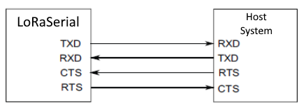
FlowControl - If flow control is enabled, LoRaSerial will send data when its CTS pin is driven low (the host system is telling the radio to transmit). If flow control is enabled, LoRaSerial will drive its RTS low if its serial buffer is full (the radio is telling the host system to hold its horses). CTS and RTS pins are only exposed on the UART connector but if flow control is enabled, the UART flow control pins will apply to both USB and serial data streams. Internal pull-ups are used so if flow control is enabled, RTS and CTS must not be left floating. By default, flow control is turned off.
-
InvertCts - By default, InvertCts is false and CTS is high when data is allowed to flow. Enable InvertCts to do the opposite.
-
InvertRts - By default, InvertRts is false and RTS is high when data is allowed to flow. Enable InvertRts to do the opposite.
-
SerialDelay - The number of milliseconds of timeout before a partial packet is sent. For example, if a partial frame of 12 bytes is received, the radio will wait this amount for more bytes before initiating a transmission. The default is 50ms. Allowed values: 10 to 2000ms.
-
SerialSpeed - Controls the baud rate in bits-per-second used over the UART connector. Data sent over USB will be sent/received regardless of this setting. The default is 57600bps. Allowed values are 2400, 4800, 9600, 14400, 19200, 38400, 57600, and 115200bps.
-
UsbSerialWait - If enabled, the radio will wait for the USB port to be enumerated and open before beginning operation. The default is false.
Info Commands
| AT Command | Command Description |
|---|---|
| ATI0 | Show user settable parameters |
| ATI1 | Show board variant |
| ATI2 | Show firmware version |
| ATI3 | Display RSSI value |
| ATI4 | Get random byte from RSSI |
| ATI5 | Show max possible bytes per second |
| ATI6 | Display current radio state |
| ATI7 | Show current FHSS channel |
| ATI8 | Display system unique ID |
| ATI9 | Display the maximum datagram size |
| ATI10 | Display radio metrics |
| ATI13 | Display the SX1276 registers |
| ATI14 | Dump the radioTxBuffer |
-
ATI0 - List all available AT commands.
-
ATI1 - Shows the board variant. For example "SparkFun LoRaSerial SAMD21 1W 915MHz".
-
ATI2 - Shows the LoRaSerial firmware version. For example "2.0".
-
ATI3 - Shows the last RSSI during a successful reception. For example "-76".
-
ATI4 - Queries the radio for a random byte, 0 to 255, based on RF noise. For example "42".
-
ATI5 - Based on settings, returns the ideal number of bytes capable of being transmitted over the link. This number assumes no retransmits and should be used only as a guide to set expectations of the host system.
-
ATI6 - Displays the current radio state. For example: "State: P2P: Receiving Standby LinkUptime: 2:45:08".
-
ATI7 - Displays the current channel number. For example: "29".
-
ATI8 - Displays the unique 32-character, 16-byte, 128-bit value marked into the SAMD21 microcontroller. For example: "5BCEDAE13630595020312E32102317FF".
-
ATI9 - Displays the maximum number of bytes that can be transmitted. Different radio settings will use fewer or a greater number of bytes for overhead. For example: "249".
-
ATI10 - Displays a large number of metrics related to the radio link including datagrams sent, link uptime, ACK counts, buffer states, etc.
-
ATI13 - Displays the contents of all the registers in the SX1276 LoRa transceiver.
-
ATI14 - Displays the contents of the current transmit buffer.
Remote Training
Currently, only one remote command is supported - RTT. Issuing this command to the local radio when the link is up will cause the remote radio to drop from the link and enter training mode. The remote radio will wait in this mode until training is completed, a local ATZ command is entered into the remote device, or the Train button is pressed on the remote device.
This command is generally used to remotely configure a radio. First, the RTT command is issued, the local radio is configured (including enabling Server), then the ATT is issued to push the local radio into training. Because the local radio is the server, its settings are set to the remote radio. The remote radio will reset and start with these newly issued settings. The local radio needs to reset with an ATZ command and the link should be re-established with new settings. Below is a command script to achieve this remote configuration. We assume the radios are currently linked at the start of the script.
Note: RTT is only supported in P2P mode.
+++
RTT
AT-Server=1
AT-AirSpeed=9600
ATW
ATT
(Wait for the 'Client XYZ Trained' message)
ATZ