Installation & Setup
CH340 Driver
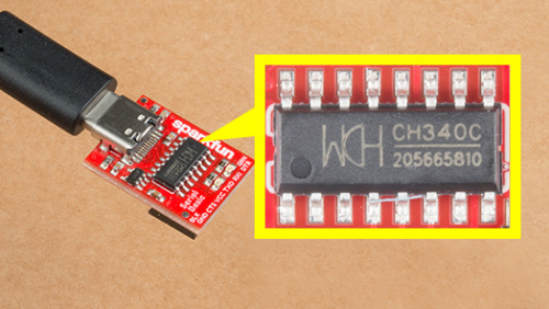
Users will need to install the appropriate driver for their computer to recognize the serial-to-UART chip on their board/adapter. Most of the latest operating systems will recognize the CH340C chip on the board and automatically install the required driver.
To manually install the CH340 driver on their computer, users can download it from the WCH website. For more information, check out our How to Install CH340 Drivers Tutorial.
Arduino IDE
Tip
For first-time users, who have never programmed before and are looking to use the Arduino IDE, we recommend beginning with the SparkFun Inventor's Kit (SIK), which is designed to help users get started programming with the Arduino IDE.
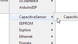
Most users may already be familiar with the Arduino IDE and its use. However, for those of you who have never heard the name Arduino before, feel free to check out the Arduino website. To get started with using the Arduino IDE, check out our tutorials below:
Install Board Definition
Install the latest ESP32 board definitions in the Arduino IDE.
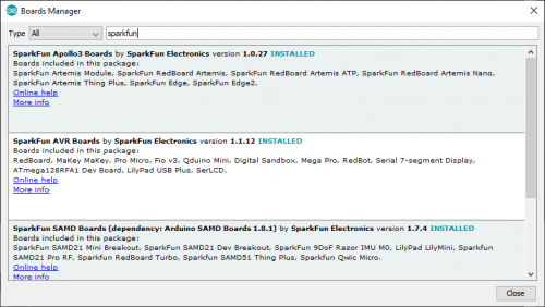
Installing Board Definitions in the Arduino IDE
Info
For more instructions, users can follow this tutorial on Installing Additional Cores provided by Arduino. Users will also need the .json file for the Espressif Arduino core:
https://raw.githubusercontent.com/espressif/arduino-esp32/gh-pages/package_esp32_index.json
When selecting a board to program in the Arduino IDE, users should select the SparkFun ESP32 Thing Plus C from the Tools drop-down menu (_i.e. Tools > Board > ESP32 Arduino > SparkFun ESP32 Thing Plus C). Alternatively, users can also select the ESP32 Dev Module; however, they may lose some pin assignments.
Select the SparkFun ESP32 Thing Plus C from the Tools drop-down menu in the Arduino IDE.
Arduino IDE 2.x.x - Alternative Method
In the newest version of the Arduino IDE 2.x.x, users can also select their board (green) and port (blue) from the Select Board & Port dropdown menu (yellow).

SparkFun TMAG5273 Arduino Library
The SparkFun TMAG5273 Arduino Library can be installed from the library manager in the Arduino IDE.
SparkFun TMAG5273 Arduino library in the library manager of the Arduino IDE.
Arduino IDE (v1.x.x)
In the Arduino IDE v1.x.x, the library manager will have the following appearance for the SimpleFOC library:

This library will be primarily used to interact with the TMAG5273 hall-effect sensor and return the rotation angle of the motor.
SimpleFOC Arduino Library
The Simple Field Oriented Control Library can be installed from the library manager in the Arduino IDE.
SimpleFOC library in the library manager of the Arduino IDE.
Arduino IDE (v1.x.x)
In the Arduino IDE v1.x.x, the library manager will have the following appearance for the SimpleFOC library:

This library utilizes a motor control scheme called field oriented control (FOC), which can utilize a feedback control loop to drive a motor with a higher power efficiency and precision characteristics, like evenly distributed torque control.
Info
For more details about the library, check out the online documentation.
Supported Hardware
For a detailed and up-to-date list of the hardware supported by this library, check out the library's documentation. The following are excerpts taken from the library's documentation page:
Arduino SimpleFOClibrary supports:
| MCU | 2 PWM mode | 4 PWM mode | 3 PWM mode | 6 PWM mode | pwm frequency config |
|---|---|---|---|---|---|
| Arduino (8-bit) | ✔️ | ✔️ | ✔️ | ✔️ | ✔️ (either 4kHz or 32kHz) |
| Arduino DUE | ✔️ | ✔️ | ✔️ | ❌ | ✔️ |
| stm32 | ✔️ | ✔️ | ✔️ | ✔️ | ✔️ |
| esp32 MCPWM | ✔️ | ✔️ | ✔️ | ✔️ | ✔️ |
| esp32 LEDC | ✔️ | ✔️ | ✔️ | ❌ | ✔️ |
| esp8266 | ✔️ | ✔️ | ✔️ | ❌ | ✔️ |
| samd21/51 | ✔️ | ✔️ | ✔️ | ✔️ | ✔️ |
| teensy | ✔️ | ✔️ | ✔️ | ✔️ | ✔️ |
| Raspberry Pi Pico | ✔️ | ✔️ | ✔️ | ✔️ | ✔️ |
| Portenta H7 | ✔️ | ✔️ | ✔️ | ❌ | ✔️ |
| nRF52 | ✔️ | ✔️ | ✔️ | ✔️ | ✔️ |
From this table you can see that if you need the 6 PWM mode for your application you should avoid using Teensy and Arduino DUE boards for now.
Info
For more details, please refer to the SimpleFOC Arduino library documentation.
Arduino SimpleFOClibrary has a goal to support as many BLDC and stepper motor drivers as possible. Till this moment there are two kinds of motor drivers supported by this library:
- BLDC motor driver
- 3 PWM signals ( 3 phase )
- 6 PWM signals ( 3 phase )
Current Limitations
Before running any BLDC motor with the SimpleFOClibrary please make sure your hardware can handle the currents your motor requires.
The simplest way to do it is by checking the motor phase resistance R. Either check the datasheet of your motor and search for the resistance value or measure it yourself using a multimeter. Then check the value of your power supply voltage V_dc and once when you have the values you can find the maximum current I_max value by calculating:
I_max with the datasheet of your driver board. If the I_max is too high you can lower the power supply voltage V_dc in order prevent too high peaks of the current. If you are not able to change your power supply voltage you can limit the voltage set to motor in software.
NOTE
The equation above calculates the worst case maximum currentI_maxand in most cases calculatedI_maxis higher than the actual value. Maximum current depends both of the motor hardware such as winding configuration and the control algorithm.
Tip
While the TMC6300 isn't directly listed as part of the supported hardware for the SimpleFOC Arduino library, we have verified that is compatible with the library.
Info
For more details, please refer to the SimpleFOC Arduino library documentation.
Arduino SimpleFOClibrary supports two types of BLDC motors:
-
BLDC motors
-
3 phase (3 wire):
Gimbal Motors
Gimbal motors will work basically with any BLDC motor driver, but since the high-performance drivers have current measurement circuits optimized for high currents you will not have any benefit of using them. Therefore low-power BLDC motor drivers will have comparable performance as the expensive high-power, high-performance drivers for gimbal motors. What is in my opinion very cool! 😃 This was one of the main motivations to start developing SimpleFOCShield.
Some of the characteristics of Gimbal motors are:
- High torque on low velocities
- Very smooth operation
- Internal resistance >10Ω
- Currents up to 5A
Gimbal motors are very versatile and their main benefit is very smooth operation on low speeds and high torque. They can be used in may different applications everywhere from being a high-quality replacement for your stepper motor or DC servo motor to very smooth camera gimbals and many different robotics applications. One of very interesting use cases are student experiments, where BLDC motors provide a very high degree of control and dynamics, such examples are ball and plate, inverted pendulums, balancing robots and similar.
High-performance Motors
Gimbal motors are just a subset of all the BLDC motors there is. As suggested in previous chapters, when using high-torque ( currents > 5A), low-resistance (~1Ω) BLDC motors such as drone motors make sure your BLDC driver can support the currents necessary. SimpleFOClibrary has been tested with several high performance BLDC drivers (supported BLDC drivers list).
-
-
Stepper motors
- 2 phase (4 wire)
Current Limitations
Before running any BLDC motor with the SimpleFOClibrary please make sure your hardware can handle the currents your motor requires.
The simplest way to do it is by checking the motor phase resistance R. Either check the datasheet of your motor and search for the resistance value or measure it yourself using a multimeter. Then check the value of your power supply voltage V_dc and once when you have the values you can find the maximum current I_max value by calculating:
I_max with the datasheet of your driver board. If the I_max is too high you can lower the power supply voltage V_dc in order prevent too high peaks of the current. If you are not able to change your power supply voltage you can limit the voltage set to motor in software.
NOTE
The equation above calculates the worst case maximum currentI_maxand in most cases calculatedI_maxis higher than the actual value. Maximum current depends both of the motor hardware such as winding configuration and the control algorithm.
Info
For more details, please refer to the SimpleFOC Arduino library documentation.
6PWM Motor Driver
Users will need to utilize the BLDCDriver6PWM class to provide the six PWM signals required for the TMC6300 motor driver.
BLDCDriver6PWM-
This class provides an abstraction layer for most of the common BLDC drivers, which require six PWM signals. This method offers more control than a three PWM motor drivers, since each of the 6 half-bridges MOSFETs can be controlled independently.
To create the interface to the BLDC driver you need to specify the 6
PWMpin numbers for each motor phase and optionallyenablepin.// BLDCDriver6PWM( int phA_h, int phA_l, int phB_h, int phB_l, int phC_h, int phC_l, int en) // - phA_h, phA_l - A phase pwm pin high/low pair // - phB_h, phB_l - B phase pwm pin high/low pair // - phB_h, phC_l - C phase pwm pin high/low pair // - enable pin - (optional input) BLDCDriver6PWM driver = BLDCDriver6PWM(5,6, 9,10, 3,11, 8);Microcontroller Considerations
Arduino UNO and all the atmega328 based boards have only 6 PWM pins and in order to use the
BLDCDrievr6PWMwe need to use all of them. Those are3,5,6,9,10and11. Furthermore in order for the algorithm to work well we need to use the PWM pins that belong to the same timer for each high/low side pair of each phase. So Atmega328 pins belonging to the timers are:TIM0TIM1TIM25,69,103,11Therefore it is important that
phA_handphA_lbelong to one timer,phB_handphB_lto second timer andphC_handphC_lto the last timer. If we decide that phaseAbelongs to the timerTIM0we can setphA_heither to pin5or pin6.Stm32 boards have two possible 6 PWM modes:
- Hardware 6 PWM mode
- Software 6 PWM mode
-
Hardware PWM
In hardware 6 PWM mode the user uses only one timer, usually Timer 1 for all the 6 PWM channels. Stm32 boards usually have at least one timer which has automatic complementary channels which avoids the need for a complicated channel inverting configuration. SimpleFOClibrary automatically enables this control mode if you provide the pins that support this interface to the constructor of the
BLDCDriver6PWMclass. For example, both STM32 Bluepill and STM32 Nucleo boards have this interface supported by pins:T1C1T1C2T1C3T1C1NT1C2NT1C3NPA8PA9PA10PB13PB14PB15Where
T1Cxare the Timer 1 channels andT1CxNare their complementary channels (inverted channels). Each pair ofT1CxandT1CxNis used for one pair of the high/low PWM pins. The library will configure the necessary timers and registers if you provide these pins to the constrictor of theBLDCDriver6PWMclass. For example: -
Software PWM
If it is not possible to use the hardware 6 PWM mode with your board SimpleFOClibrary enables you to use any two channels of any of the timers as your high/low side PWM pair. Basically, the library will automatically configure the complementary channels on the provided low side pins. The only requirement for this code to work properly is exatcly the same as for the Arudino UNO, each phase high/low PWM pair needs to belong to the same timer. For example, if we take STM32 Nucleo F401RE board we can take for example:
Where// BLDCDriver6PWM( int phA_h, int phA_l, int phB_h, int phB_l, int phC_h, int phC_l, int en) BLDCDriver6PWM driver = BLDCDriver6PWM(7, 2, 6, 3, 5, 4);T1C1T1C3T2C3T2C2T3C1T3C2726354On Bluepill we could use:
Where// BLDCDriver6PWM( int phA_h, int phA_l, int phB_h, int phB_l, int phC_h, int phC_l, int en) BLDCDriver6PWM driver = BLDCDriver6PWM(PA8, PA9, PB6, PB7, PB8, PB9);T1C1T1C2T4C1T4C2T4C3T4C4PA8PA9PB6PB7PB8PB9
ESP32 boards support
MCPWMinterface that is intended for this kind of applications. Each ESP32 board has two of theMCPWMchannels and can support two 6 PWM drivers. There is no pin specific requirements for the ESP32, each pin can be used in PWM mode. But please make sure not to use the pins that have predefined states on boot because this could result malfunction. You can find this information online easily, here is a YouTube video with more details.Info
For more details about the
BLDCDriver6PWMclass, check out the online documentation.
BLDC Motor
All BLDC motors are handled with the BLDCMotor class.
BLDCMotor-
This class implements the BLDC FOC algorithm, motion control loops, and monitoring.
To instantiate the BLDC motor we need to create an instance of the
BLDCMotorclass and provide it the number ofpole pairsof the motor.// BLDCMotor(int pp, (optional R, KV)) // - pp - pole pair number // - R - phase resistance value - optional // - KV - motor KV rating [rpm/V] - optional BLDCMotor motor = BLDCMotor(11, 10.5, 120);Motor Considerations
While, the datasheet for our gimbal motor, indicates that there are 8 pole pairs, we have found that the motor operates more smoothly if the
BLDCMotorclass is instantiated with 7 pole pairs instead.Info
For more details about the
BLDCMotorclass, check out the online documentation.
Position Sensor
In order to incorporate the TMAG5273 hall-effect sensor into the FOC algorithm, users will need to utilize the GenericSensor class.
GenericSensor-
This class allows users to link a custom position sensor (not already implemented in the SimpleFOC library) by incorporating a few functions into their sketch.
-
Implement two functions; one to initialize the TMAG5273 and another to read and return the sensor's current position.
-
Instantiate the
GenericSensorclass and initialize the class by providing it pointers to the two functions. -
There are two ways to use sensors implemented within the SimpleFOC library:
- As standalone position sensor
- In this configuration users would simply read the sensor's position, independently from incorporating the readings into the FOC algorithm.
-
Incorporate it as the motor position sensor for FOC algorithm
-
Initialize the sensor in the
setup()loop: -
Link the sensor in the
setup()loop:
-
- As standalone position sensor
-
Info
For more instructions on incorporating the GenericSensor class, please refer to the SimpleFOC documentation.
In-line Current Sensing
In order to incorporate the current sensing into the FOC algorithm, users will need to utilize the InlineCurrentSense class.
InlineCurrentSense-
This class allows users to link a custom position sensor (not already implemented in the SimpleFOC library) by incorporating a few functions into their sketch.
-
Instantiate the
InlineCurrentSenseclass and initialize the class by providing the hardware configuration.To instantiate the inline current sensor using the SimpleFOClibrary just create an instance of the class
InlineCurrentSense. ```cpp // InlineCurrentSensor constructor // - shunt_resistor - shunt resistor value // - gain - current-sense op-amp gain // - phA - A phase adc pin // - phB - B phase adc pin // - phC - C phase adc pin (optional) InlineCurrentSense current_sense = InlineCurrentSense(0.01, 20, A0, A1, A2); -
Incorporate the current sensor into the FOC algorithm:
-
Initialize the sensor in the
setup()loop:Once the current sense has been created it can be initialised. This
init()function configures the ADC hardware for reading and finds the zero offsets of the ADC for each channel. ```cpp // init current sense current_sense.init(); -
Link the sensor to the motor driver in the
setup()loop:To use the
InlineCurrentSensewith the FOC algorithm, first thing you'll need to do is to associate (link) your current sense with theBLDCDriver: ```cpp // link current sense and driver current_sense.linkDriver(&driver); -
Link the sensor to the motor in the
setup()loop:Once the driver is linked to the current sense, last step is to link the current sense with the
BLDCMotoryou wish to use it with: ```cpp // link motor and current sense motor.linkCurrentSense(¤t_sense);
It is very important that the the current sensing
initfunction is called after theBLDCMotorandBLDCDriverinit functions are called. Which will make sure that the driver is enabled when current sense calibration is taking place. Also, it is important that the current senseinitfunction is called before starting the foc algorithm with theinitFOCfunction.So the suggested code structure would be:
```cpp void loop(){ .... // driver init driver.init(); // link the driver to the current sense current_sense.linkDriver(&driver); .... // motor init motor.init(); .... // init current sense current_sense.init(); // link the current sense to the motor motor.linkCurrentSense(¤t_sense); ... // start the FOC motor.initFOC(); }
-
-
Info
For instructions on incorporating the InlineCurrentSense class, please refer to the SimpleFOC documentation.
