Introduction
-
SparkFun Quadband GNSS RTK Breakout - LG290P (Qwiic)
SKU: GPS-26620

-
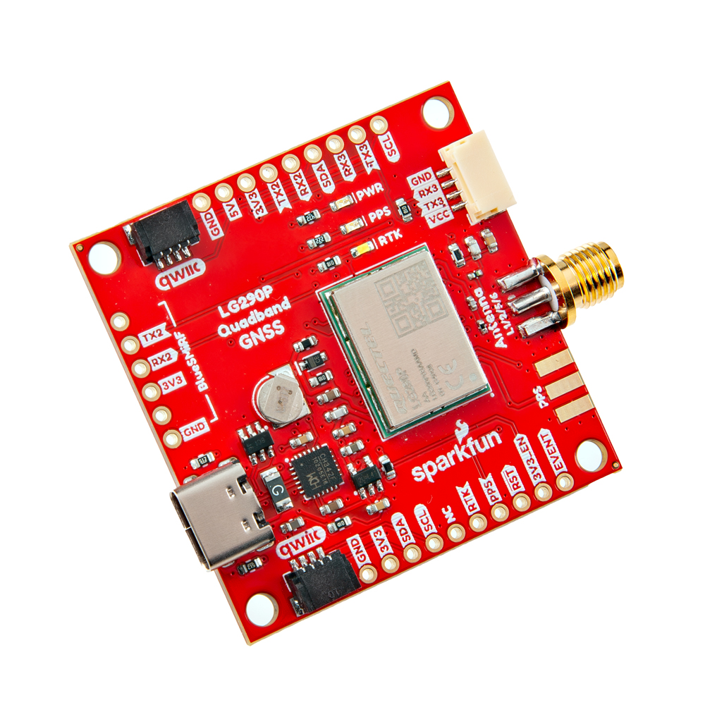
The SparkFun Quadband GNSS RTK Breakout - LG290P (Qwiic) features the Quectel LG290P GNSS module. The board's dimensions, pin layout, and connectors are exactly the same as our very popular SparkFun GPS-RTK-SMA Breakout - ZED-F9P (Qwiic); and can be used as a drop-in replacement. The board also accommodates users with a diverse choice of interfaces including UART, SPI1, and I2C1.
The LG290P module is a quad-band, multi-constellation, high-precision, RTK GNSS receiver. The module is capable of simultaneously receiving signals from the
L1,L2,L5, andL6/E6frequency bands of the GPS, GLONASS, Galileo, BDS, QZSS, and NavIC GNSS constellations. In addition, the module supports SBAS augmentation systems (WASS, EGNOS, BDSBAS, MSAS, GAGAN, and SDCM), PPP services2 (BDS PPP-B2b, QZSS CLAS, MADOCA-PPP, and Galileo HAS), and RTK corrections for precision navigation with a fast convergence time and reliable performance.The built-in NIC anti-jamming unit provides professional-grade interference signal detection and elimination algorithms, which effectively mitigate against multiple narrow-band interference sources and significantly improves the signal reception performance in complex electromagnetic environments. Additionally, the embedded algorithms ensure reliable positioning in complex scenarios such as urban environments and deep tree cover.
With its performance advantages of high-precision and low power consumption, this board is an ideal choice for high-precision navigation applications, such as intelligent robots, UAVs, precision agriculture, mining, surveying, and autonomous navigation.
Features Under Development
- I2C/SPI - Currently, only the UART interface is supported by the module.
- PPP Services - Corrections for some of the PPP services have not been implemented.
Required Materials
To get started, users will need a few items. Some users may already have a few of these items, feel free to adjust accordingly.
- Computer with an operating system (OS) that is compatible with all the software installation requirements
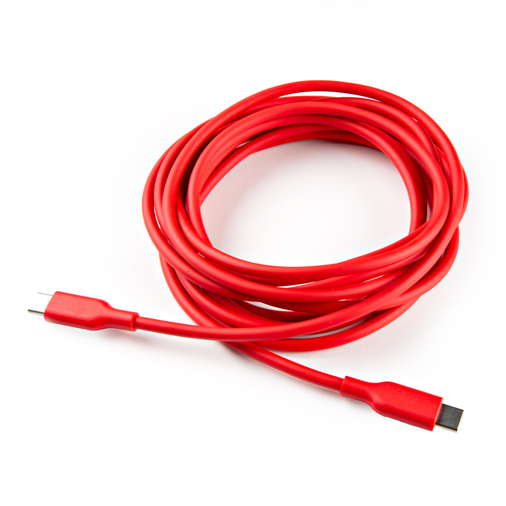
- USB 3.1 Cable A to C - 3 Foot - Used to interface with the SparkFun Quadband GNSS RTK Breakout - LG290P (Qwiic) (1)
- SparkFun Quadband GNSS RTK Breakout - LG290P (Qwiic)
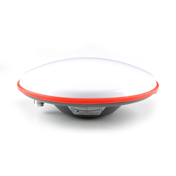
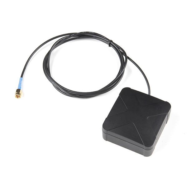
- GNSS Multi-Band L1/L2/L5 Surveying Antenna
- If your computer doesn't have a USB-A slot, then choose an appropriate cable or adapter.
GNSS Antennas & Accessories
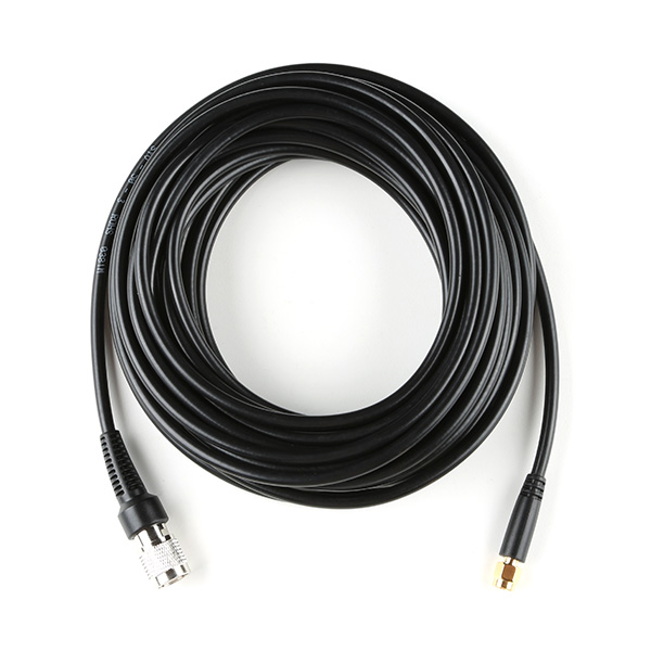
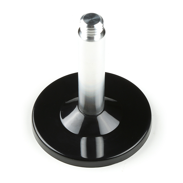
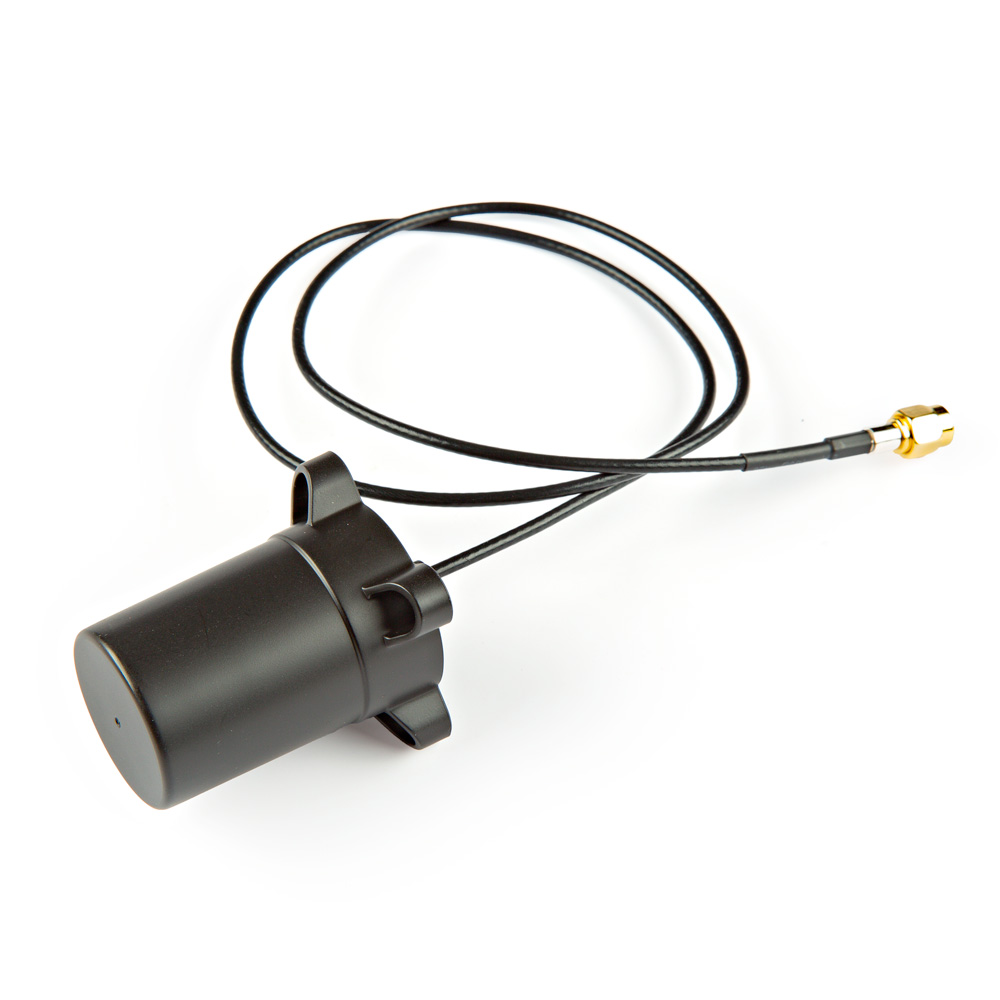
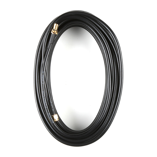
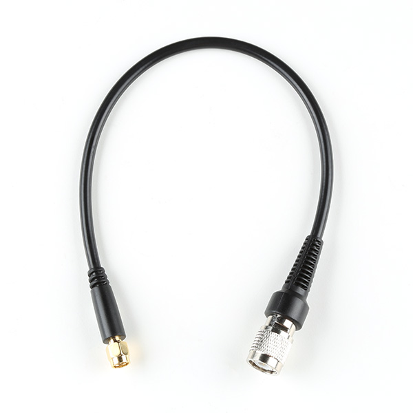
For the best performance, we recommend users choose an active, multi-band GNSS antenna and utilize a low-loss cable. For additional options, please check out the GPS Antenna category of our product catalog.
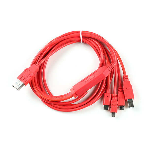
Serial Transceivers, UART Adapters, and USB Cables
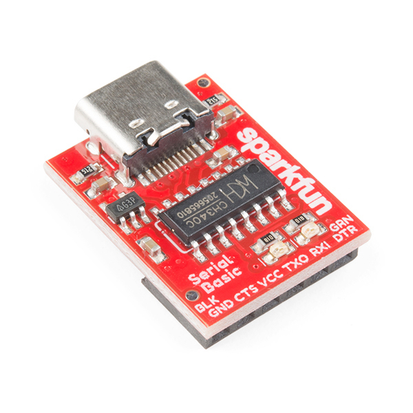
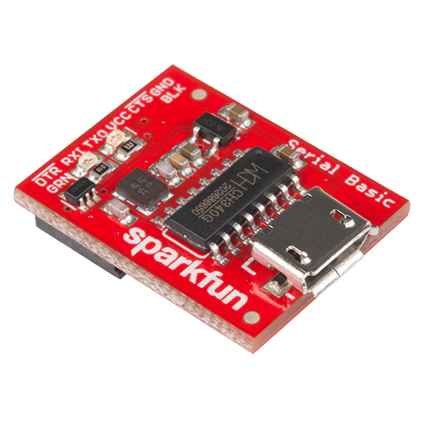
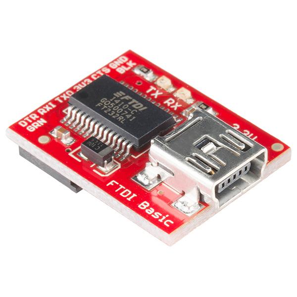
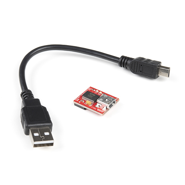
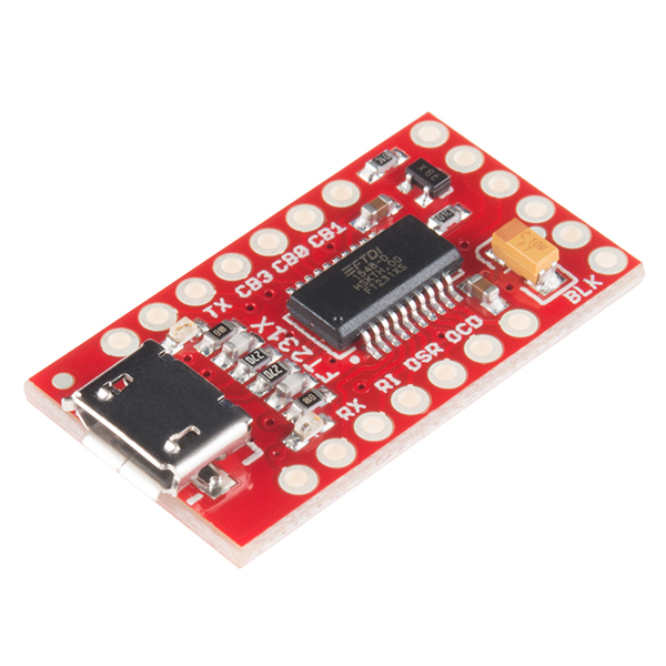
To configure the UART ports that are broken out on the board, users will need a UART adapter. Once configured, the UART ports can utilize one of our RF transceivers to send/receive RTCM messages.
-
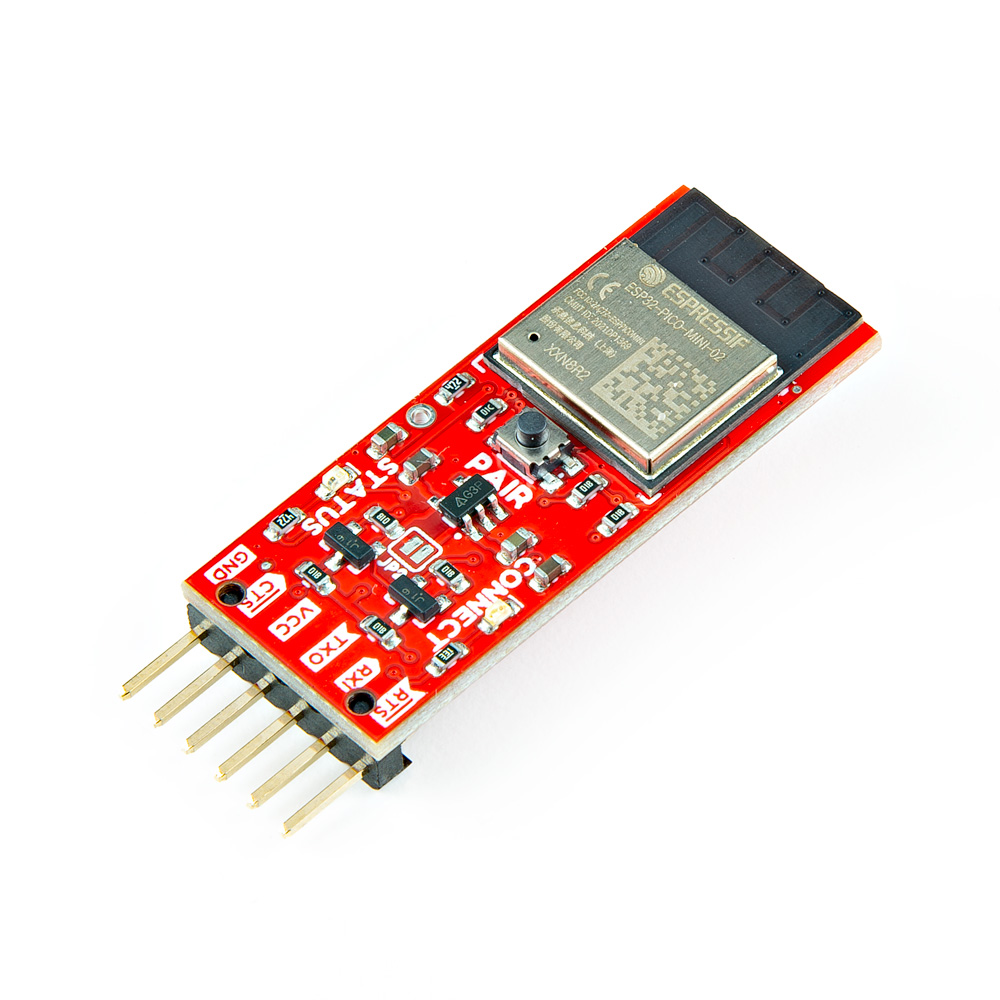
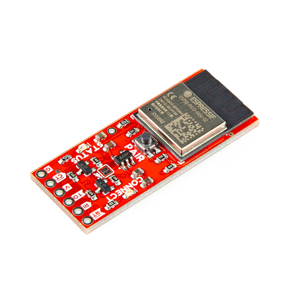
SparkFun BlueSMiRF v2 - Headers
WRL-23287 -
SparkFun BlueSMiRF v2
WRL-24113 -
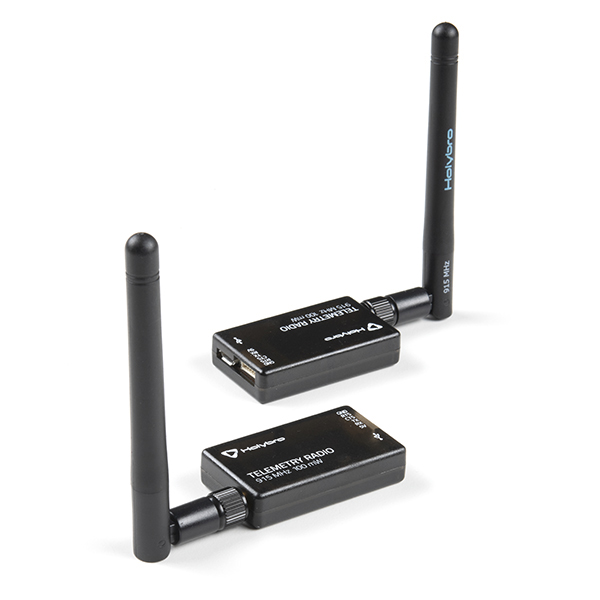
SiK Telemetry Radio V3 - 915MHz, 100mW
WRL-19032 -
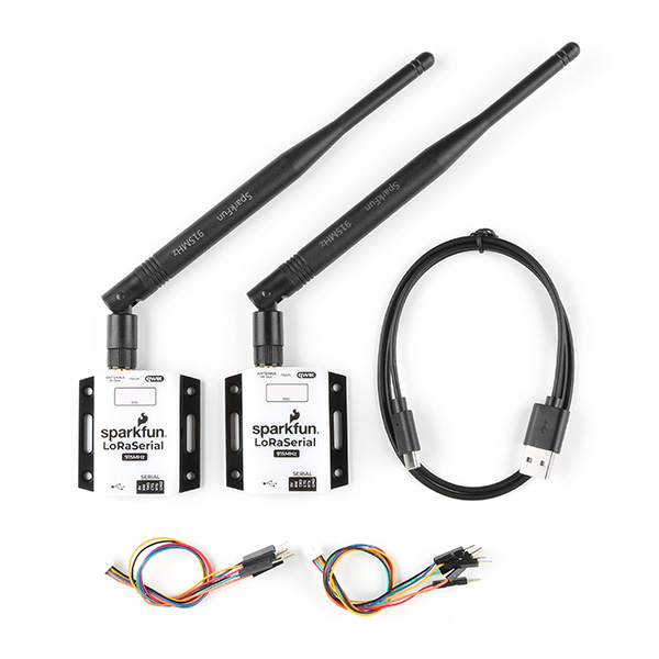
SparkFun LoRaSerial Kit - 915MHz (Enclosed)
WRL-20029 -
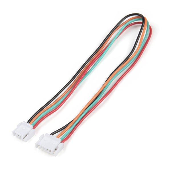
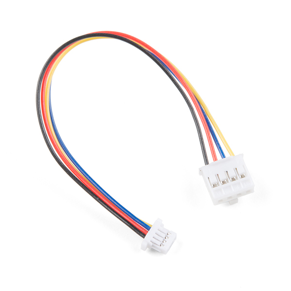
JST-GHR-04V to JST-GHR-06V Cable - 1.25mm pitch
CAB-17239 -
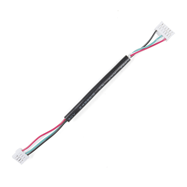
GHR-04V-S to GHR-06V-S Cable - 100mm
CAB-17854 -
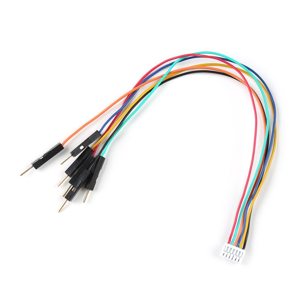
Breadboard to JST-GHR-06V Cable - 6-Pin x 1.25mm Pitch (For LoRaSerial)
CAB-23353 -
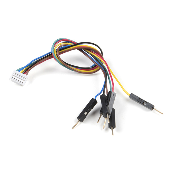
Breadboard to JST-GHR-06V Cable - 6-Pin x 1.25mm Pitch
CAB-18079 -
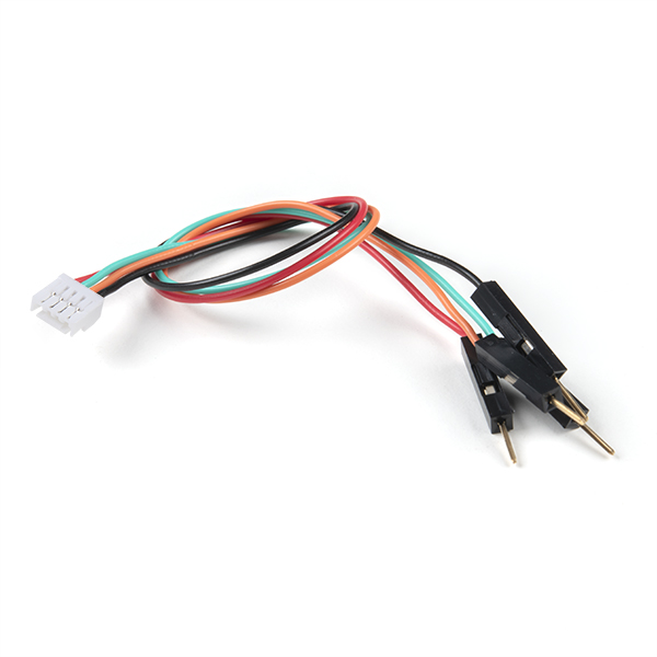
Breadboard to JST-GHR-04V Cable - 4-Pin x 1.25mm Pitch
CAB-17240
Headers and Wiring
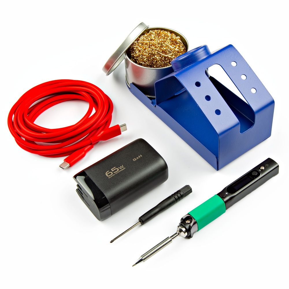
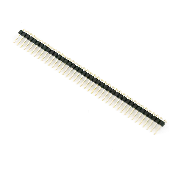
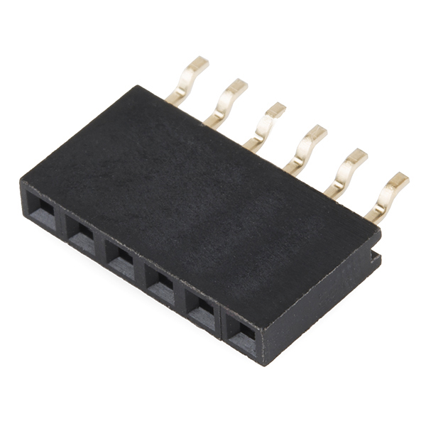
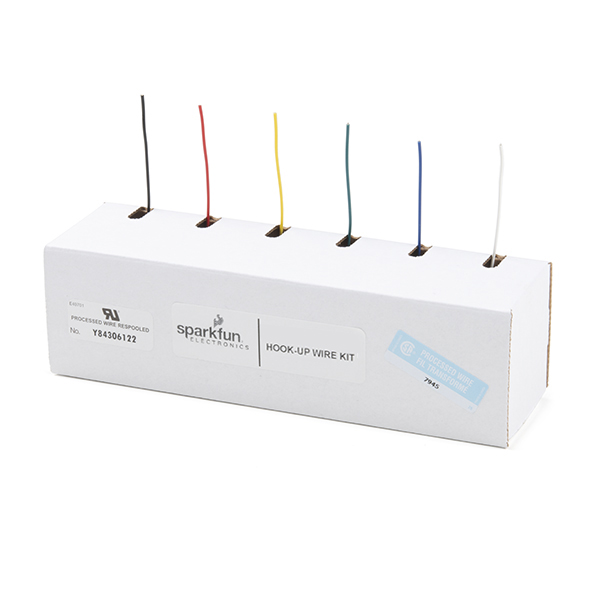
To add headers or wiring, users will need soldering equipment and headers/wires.
New to soldering?
Check out our How to Solder: Through-Hole Soldering tutorial for a quick introduction!
Qwiic Devices and Cables
Our Qwiic connect system is a simple solution for daisy chaining I2C devices without the hassle of soldering or checking wire connections. Check out other Qwiic devices from our catalog.
What is Qwiic?
The Qwiic connect system is a solderless, polarized connection system that allows users to seamlessly daisy chain I2C boards together. Play the video, to learn more about the Qwiic connect system or click on the banner above to learn more about Qwiic products.

Features of the Qwiic System


Qwiic cables (4-pin JST) plug easily from development boards to sensors, shields, accessory boards and more, making easy work of setting up a new prototype.


There's no need to worry about accidentally swapping the SDA and SCL wires on your breadboard. The Qwiic connector is polarized so you know you’ll have it wired correctly every time.
The part numbers for the PCB connector is SM04B-SRSS (Datasheet) and the mating connector on the cables is SHR04V-S-B; or an equivalent 1mm pitch, 4-pin JST connection.


It’s time to leverage the power of the I2C bus! Most Qwiic boards will have two or more connectors on them, allowing multiple devices to be connected.
Jumper Modification
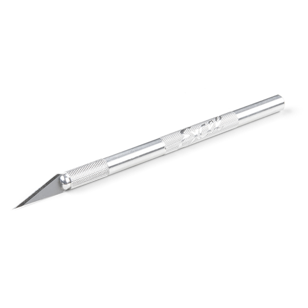
To modify the jumpers, users will need soldering equipment and/or a hobby knife.
New to jumper pads?
Check out our Jumper Pads and PCB Traces Tutorial for a quick introduction!
Suggested Reading
As a more sophisticated product, we will skip over the more fundamental tutorials (i.e. Ohm's Law and What is Electricity?). However, below are a few tutorials that may help users familiarize themselves with various aspects of the board.
Tip
Check out the www.gps.gov website to learn more about the U.S.-owned Global Positioning System (GPS) and the Global Navigation Satellite Systems (GNSS) of other countries.
Related Blog Posts
Additionally, users may be interested in these blog post articles on GNSS technologies:


