Introduction
-
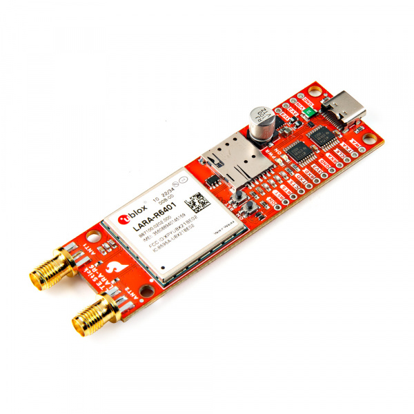
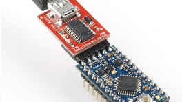
SparkFun LTE Stick - LARA-R6
SKU: CEL-23618
-
The SparkFun LTE Stick - LARA-R6 is a development and prototyping platform for the LARA-R6401 LTE module from ublox™. The LTE Stick uses the LARA-R6401 version which supports both data and voice for North America and works with LTE bands used by these mobile networks: AT&T, Verizon, T-Mobile, and FirstNet. The board includes a nanoSIM card slot for users to select their preferred network. Check with your network provider for compatibility with the LARA-R6.
The LARA-R6 workss on multiple LTE FDD frequency bands (2, 4, 5, 12, 13, 14, 66, and 71) and includes a host of common features users expect from u-blox modules including uFOTA (over-the-air firmware update), Root of Trust, secure boot/update, jamming detection, antenna and SIM detection, and much more.
The LTE Stick routes the UART and I2S interfaces to a 0.1"-spaced plated-through-hole (PTH) header along with the Reset and Power On signals and we designed the board to specifically mount on to a breadboard for easy prototyping. The board has two SMA connectors for the LARA-R6's primary and secondary antennas.
Purchase from SparkFun
Required Materials
The LTE Stick requires a few peripheral items including antennas, USB-C cable, and supported SIM card to get it up and running. Below are a few recommended options for each.
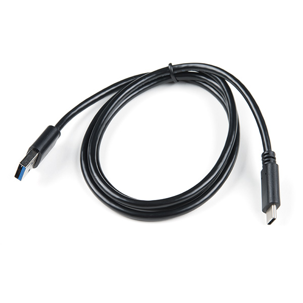
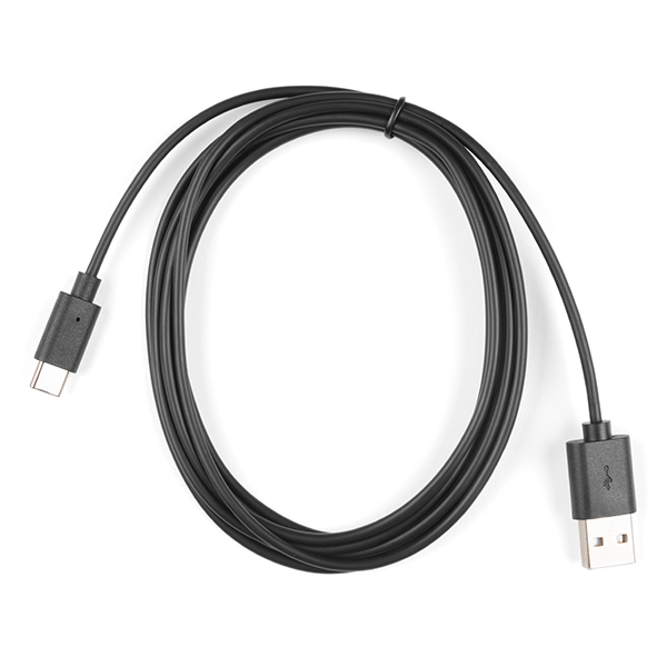
USB-C Cable
For basic use and conifguration of the LTE Stick using AT commands or u-blox's m-center software you'll need USB-C cable to connect the dev board to your computer:
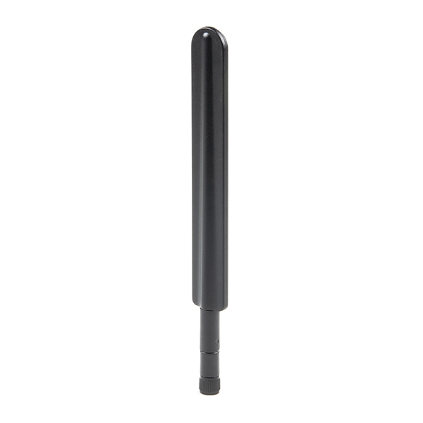
LTE Antenna
The LTE Stick has two SMA connectors for the Primary and Secondary antenna signals on the LARA-R6. The LARA-R6 only requires the Primary antenna for basic functionality but u-blox recommends connecting the Secondary antenna for best signal quality. We recommend using an antenna like the one below:
SIM Card
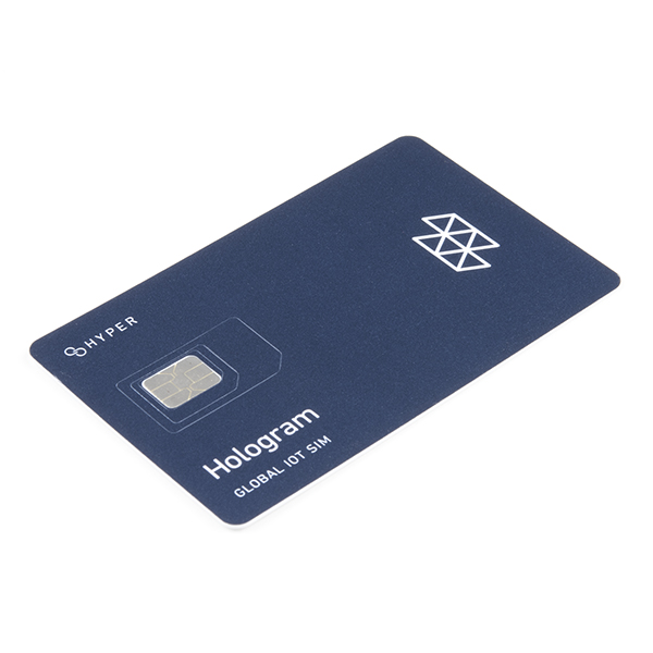
Finally, the LTE Stick requires a nano SIM card for cellular network connectivity. As mentioned above, the LTE Stick uses the LARA-R6401 module and supports only North American LTE networks and works with the AT&T, Verizon, T-Mobile, and FirstNet cellular networks though make sure to check with your selected network provider for compatibility with the LARA-R6 before purchasing. The Hologram SIM card listed below works with the LARa-R6 for data and receiving SMS but not voice or sending SMS:
Optional Materials
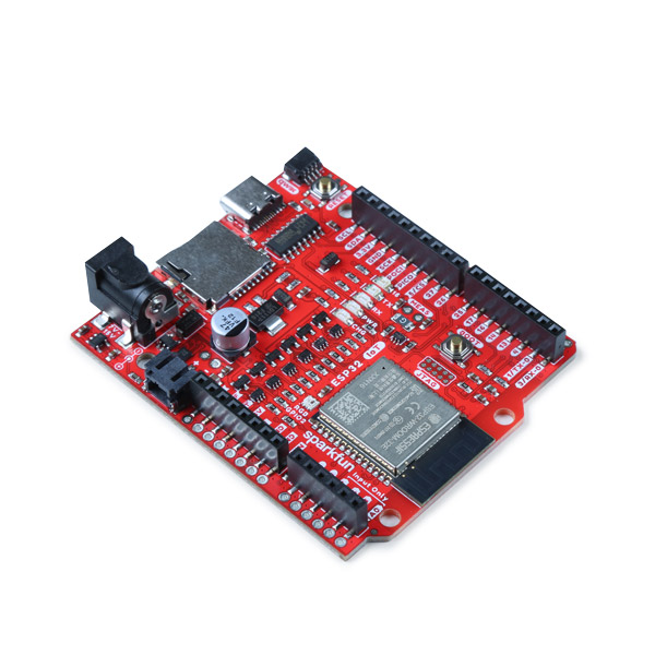
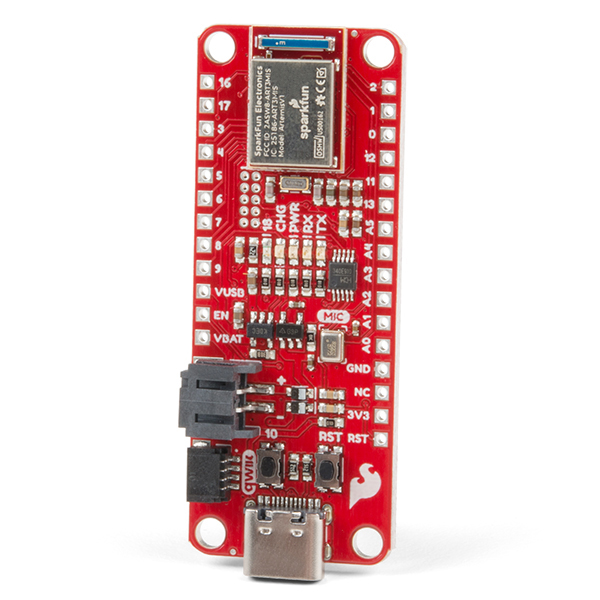
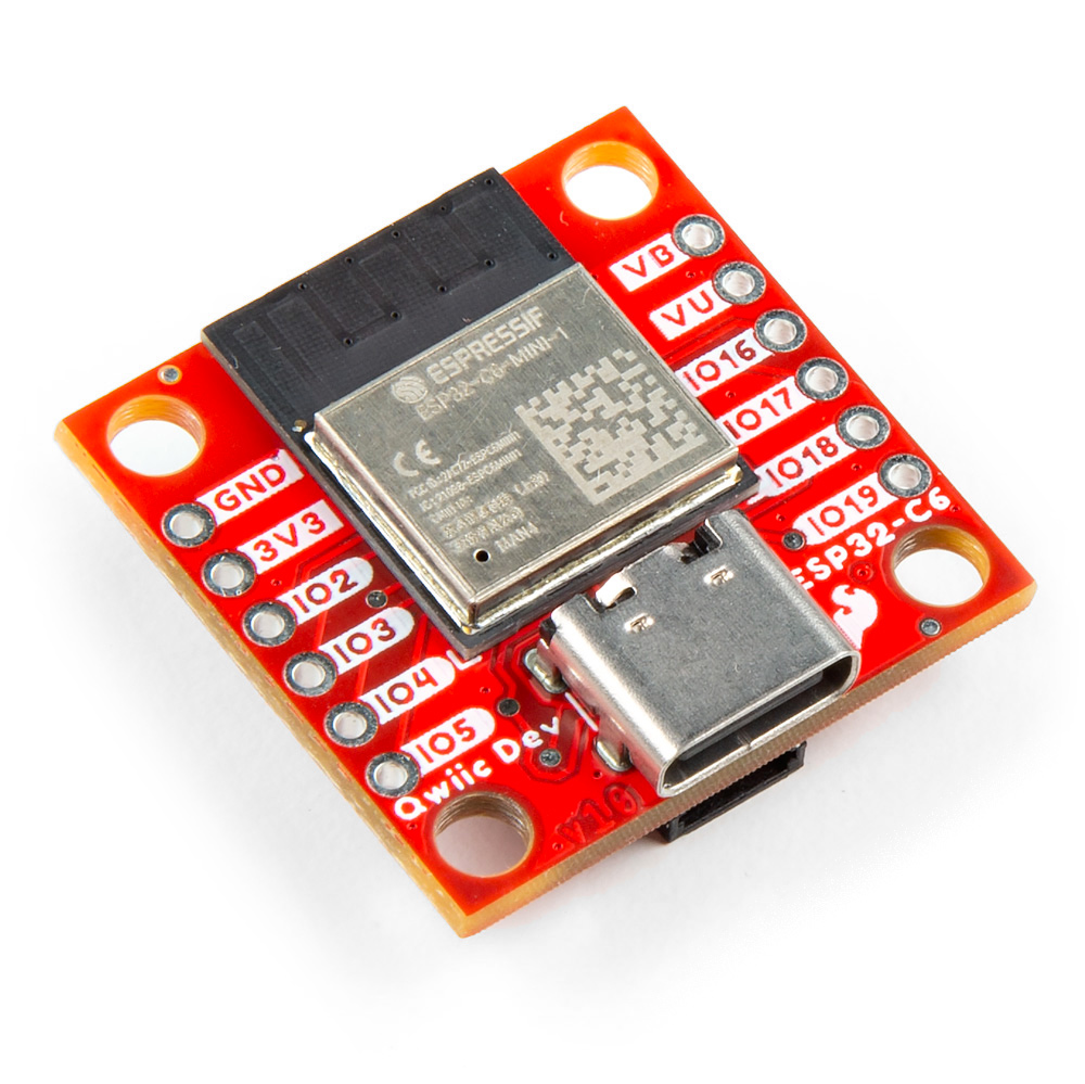
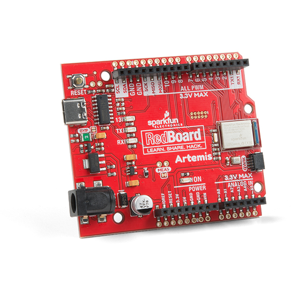
Using the LTE Stick with the SparkFun u-blox Cellular Arduino Library requires a connection to a microcontroller/development board. Below are a few options that will work with the LTE Stick out of the box.
Development Boards
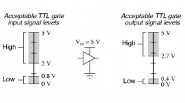
Logic Levels
The LTE Stick operates at 3.3V logic so make sure your chosen development board operates at the same logic level or use a level shifter.

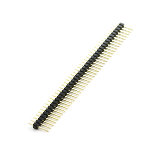
If you prefer to use the LTE Stick with a development board or simply prefer a soldered connection or want to modify the solder jumpers on these Qwiic breakouts you you may need some of the products listed below:
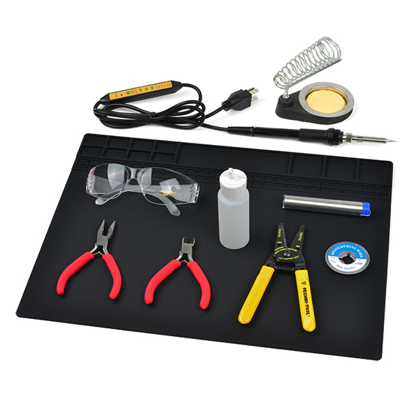
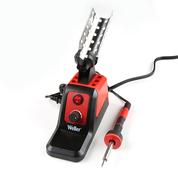
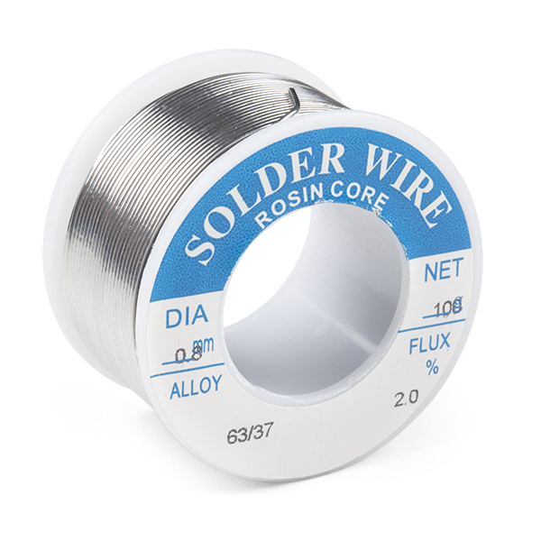
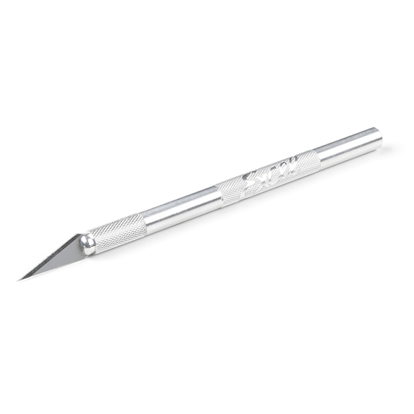
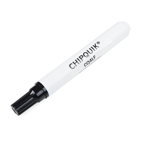
Soldering Tools & Accessories
Suggested Reading
Before getting started with this Hookup Guide, you may want to read through the tutorials below if you are not familiar with the concepts covered in them or want a refresher. If you are using either of the Qwiic Shields linked above, we recommend reading through their respective Hookup Guides before continuing with this tutorial:


Hardware Overview
LARA-R6 LTE Module
The heart of the LTE Stick is the LARA-R6 LTE Cat 1 module from u-blox. The LARA-R6401 supports data, SMS, and voice over LTE bands and works with most major North American carriers (Verizon, TMobile, AT&T, etc.).

The LARA-R6 has the following interfaces: USB, 2x UART, I2S, I2C, SIM interface, and nine GPIO pins. It also has a host of features including device security through Root of Trust (RoT) with secure boot and update, firmware updates both over the air (uFOTA) and through AT commands, dynamic antenna tuning, jamming detection, and much more. For a complete overview of these features and other information on the LARA-R6401, refer to the datasheet. The R6401 supports LTE FDD bands from 600 MHz to 1900 MHz (2, 4, 5, 12, 13, 14, 66, and 71).
Pinout
The board breaks out the LARA-R6's UART and I2S interfaces as well as the Power On, Reset and voltage pins to a pair of 0.1"-spaced PTH (plated through-hole) headers.

The list below outlines the functionality of pins broken out on the LTE Stick:
- PWR_On - LARA-R6 power control pin
- Reset - LARA-R6 reset pin
- RXD - UART data out
- TXD - UART data in
- CTS - UART clear to send
- RTS - UART ready to send
- RXA - I2S receive data
- CLK - I2S clock
- TXA - I2S transmit data
-
WA - I2S word alignment
-
VIN - 5V
- 3.3V - Regulated 3.3V
- 1.8 - Regulated 1.8V
Test Points
Warning
All three of these clusters have test point connections for 1.8V and GND and connect directly to the associated pins on the LARA-R6. These pins are not level-shifted and run at 1.8V logic. Take care when interacting with these pins to avoid damaging the signals they connect to.
The LTE Stick also has several other interfaces broken out to test points for advanced users to solder to. These test points are small copper pads grouped into three clusters labeled: I2C, GPIO, and UART2. They do not have individual pin labels so refer to the board files (ZIP) to identify the pin locations.

The I2C cluster contains the LARA's I2C bus pins (SDA/SCL) as well as GPIO4. The GPIO cluster contains GPIO1, GPIO2, GPIO3, and GPIO6. All GPIO pins can act as a generic GPIO signal but some have alternate functions outlined in section 2.8 of the LARA-R6 datasheet.
The UART2 cluster contains the LARA's UART2 pins: TX2, RX2, CTS2, and RTS2. This interface is disabled by default and can be activated by the dedicated AT command. Refer to section 18.12 of the AT commands manual and section 1.9.1.2 of the integration manual for complete information on using these pins. Users also should open the DTR solder jumper to use this pin for TX2 (refer to the Solder Jumpers section for more information on the DTR jumper).
Connectors/Connections
Let's take a closer look at the connectors on the LTE Stick.
Power
The LTE Stick uses a USB-C connector for primary power input and serial communication. The board also has dedicated PTHs for the three voltage inputs on the board: 5V(VIN), 3.3V, and 1.8V along with PTHs for Ground.

Antenna Connections
The LARA-R6 has two antenna connections; Primary (ANT1) and Secondary (ANT2). The Primary antenna functions as the main antenna interface and supports TX/RX transmissions. The Secondary antenna communicates over RX only for the LTE / 3G RX diversity configuration.

Nano SIM Card Slot
The LTE Stick has an on-board Nano SIM card slot. The LTE Stick uses the LARA-R6401 which works with most major North American carriers (Verizon, TMobile, AT&T, etc.).

Buttons
The board has two buttons labeled ON and RST. The ON button connects to the LARA-R6 PWR_On pin which turns the module on and off. Tap it once to turn the module on and hold it down for three seconds to turn it off. The RST button connects to the LARA-R6's reset line and resets the module when pressed.

LEDs
The LTE Stick has a pair of red LEDs labeled PWR and ON. The PWR LED indicates whenever the 3.3V rail is powered through USB or the VIN/3.3V PTH pins. The ON LED indicates when the LARA-R6 is powered up.

Solder Jumpers
Never modified a jumper before?
Check out our Jumper Pads and PCB Traces tutorial for a quick introduction!
The LTE Stick has four solder jumpers labeled PWR_LED, ON_LED, SHLD, and DTR.

The PWR_LED and ON_LED jumpers complete the power circuits for their associated LEDs (PWR and ON). They are CLOSED by default. Open them to disable these LEDs to help conserve power. The SHLD jumper connects the USB-C connector's shield pin to ground. Open it to isolate the shield pin. The DTR jumper is CLOSED by default and pulls the LARA-R6 DTR pin to ground (LOW) to function as UART data terminal ready. Open the jumper to use the DTR pin for its secondary use as TX2 when using the UART2 test point cluster.
Board Dimensions
The board measures 3.25" x 1.00" (82.55mm x 25.40mm) with four mounting holes that fit a 4-40 screw.

Board dimensions for the SparkFun LTE Stick, in inches.
Need more measurements?
For more information about the board's dimensions, users can download the Eagle files for the board. These files can be opened in Eagle and additional measurements can be made with the dimensions tool.
Eagle - Free Download!
Eagle is a CAD program for electronics that is free to use for hobbyists and students. However, it does require an account registration to utilize the software.
 Dimensions Tool
This video from Autodesk demonstrates how to utilize the dimensions tool in Eagle, to include additional measurements:
Hardware Assembly
Basic Assembly
The fastest way to get up and running with the LTE Stick is by connecting it to a computer through the USB-C connector and then using u-blox's mcenter software.

Soldered Assembly
New to soldering?
If you have never soldered before or need a quick refresher, check out our How to Solder: Through-Hole Soldering guide.

We specifically designed this board to fit on a breadboard with headers soldered to it for easy prototype circuit building with the LARA-R6. This assembly is strongly recommended for those who wish to use the LTE Stick with the SparkFun u-blox Cellular Library to make connections between the LTE Stick, microcontroller, and other hardware (where necessary).
Note
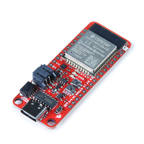
This assembly assumes the use of the SparkFun Thing Plus - ESP32 WROOM (USB-C) to make serial connections between the boards. If you are using a different microcontroller, adjust the serial connections between the two boards to the appropriate pins.
Start by soldering male headers to both sets of PTH pins on either side of the board. Next, connect the TXD and RXD pins on the LTE Stick to the Serial1 pins on the Thing Plus - ESP32 (USB-C). Finally, connect VUSB on the Thing Plus to VIN on the LTE Stick and connect the ground pins on both boards to each other. With everything wired up, your completed assembly should resemble the photo below:

u-blox Cellular Arduino Library
Software Setup
Arduino IDE
Most users may already be familiar with the Arduino IDE and its use. However, for those of you who have never heard the name Arduino before, feel free to check out the Arduino website. To get started with using the Arduino IDE, check out our tutorials below:
-
Installing the Arduino IDE
-
Installing an Arduino Library
-
Installing Board Definitions in the Arduino IDE
SparkFun u-blox Cellular Arduino Library
The SparkFun u-blox Cellular Arduino Library is a generic AT command-set library that works with multiple u-blox cellular modules that share the same AT Command Set. This includes the LARA-R6 on this board as well as the SARA-R5 and others. Most of the examples are generic and work with all modules but some require selecting a specific module to function properly.
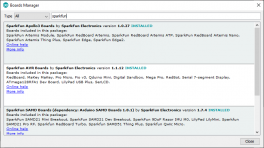
Download the library through the Arduino Library Manager tool by searching for "SparkFun u-blox Cellular" and download the latest version. Users who prefer to install it manually can download it from the GitHub repository or by clicking the button below:
With the library installed, let's move on to taking a closer look at a few of the examples included in it.
Arduino Examples
icon: simple/arduino
The SparkFun u-blox Cellular Arduino Library includes a large set of examples to do all sorts of things with supported u-blox cellular modules. Some examples work with all modules, others are limited to specific ones. All examples assume a serial connection between a microcontroller and the LTE Stick (or other supported cellular module) as demonstrated in the Hardware Assembly section. These examples build upon each other so we recommend following them in sequential order to get everything set up and working properly.
LARA-R6 Power
Make sure to power on the module using the "ON" button
If you have not used m-center or AT commands to configure the network information and register the network operator for your device before using this library, you may need to go through Example 2 - Network Info and Example 3 - Register Operator to get the LARA-R6 registered and configured properly on your network. Otherwise, feel free to skip ahead to the Ping and other more complex examples.
Example 1 - Device Identification
The first example performs the basic AT commands to return the device information of a connected module:
- Manufacturer ID
- Model
- Firmware Version
- Serial Number
- IMEI ID
- IMSI ID
- SIM CCID
- Subscriber Number (from the SIM)
- Capabilities
- SIM state
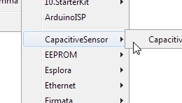
Open the example by navigating to File < Examples < SparkFun u-blox Cellular Arduino Library < Example 1 - Device Identification or copy the code below into a blank sketch.
Example 1 - Device Information
#include "SparkFun_u-blox_Cellular_Arduino_Library.h"

// Uncomment the line below that you need for Serial on your platform
#define mySerial Serial1
// SoftwareSerial mySerial(16, 17);

// Uncomment the module you're using. If your module is not listed below, then
// it's not supported for this example
SparkFun_ublox_Cellular myModule; // This example works with all modules, so the base class can be used
// SparkFun_ublox_SARA_R5 myModule; // Base SARA-R5 class
// SparkFun_ublox_SARA_R500S myModule;
// SparkFun_ublox_SARA_R500S_01B myModule;
// SparkFun_ublox_SARA_R500S_61B myModule;
// SparkFun_ublox_SARA_R510M8S_61B myModule;
// SparkFun_ublox_SARA_R510S myModule;
// SparkFun_ublox_LARA_R6 myModule; // Base LARA-R6 class
// SparkFun_ublox_LARA_R6001 myModule;
// SparkFun_ublox_LARA_R6001D myModule;
// SparkFun_ublox_LARA_R6401 myModule;
// SparkFun_ublox_LARA_R6401D myModule;
// SparkFun_ublox_LARA_R6801_00B myModule;
// SparkFun_ublox_LARA_R6801D myModule;

// Map SIM states to more readable strings
String simStateString[] = {
    "Not present",     // 0
    "PIN needed",      // 1
    "PIN blocked",     // 2
    "PUK blocked",     // 3
    "Not operational", // 4
    "Restricted",      // 5
    "Operational"      // 6
};

// processSIMstate is provided to the u-blox cellular library via a
// callback setter -- setSIMstateReadCallback. (See setup())
void processSIMstate(UBX_CELL_sim_states_t state)
{
    Serial.println();
    Serial.print(F("SIM state:           "));
    Serial.print(String(state));
    Serial.println();
}

void setup()
{
    Serial.begin(115200); // Start the serial console

    // Wait for user to press key to begin
    Serial.println(F("u-blox Cellular Example 1 - Device Identification"));
    Serial.println(F("Press any key to begin"));

    while (!Serial.available()) // Wait for the user to press a key (send any serial character)
        ;
    while (Serial.available()) // Empty the serial RX buffer
        Serial.read();

    Serial.println(F("Beginning..."));

    // myModule.enableDebugging(); // Uncomment this line to enable helpful debug messages on Serial

    // For the MicroMod Asset Tracker, we need to invert the power pin so it pulls high instead of low
    // Uncomment the next line if required
    // myModule.invertPowerPin(true);

    // Initialize the module
    if (myModule.begin(mySerial, UBX_CELL_DEFAULT_BAUD_RATE))
    {
        Serial.println(F("Module connected!"));
    }
    else
    {
        Serial.println(F("Unable to communicate with the module."));
        Serial.println(F("Manually power-on (hold the module's On button for 3 seconds) and try again."));
        while (1)
            ; // Loop forever on fail
    }
    Serial.println();

    Serial.println("Manufacturer ID:     " + String(myModule.getManufacturerID()));
    Serial.println("Model ID:            " + String(myModule.getModelID()));
    Serial.println("Firmware Version:    " + String(myModule.getFirmwareVersion()));
    Serial.println("Product Serial No.:  " + String(myModule.getSerialNo()));
    Serial.println("IMEI:                " + String(myModule.getIMEI()));
    Serial.println("IMSI:                " + String(myModule.getIMSI()));
    Serial.println("SIM CCID:            " + String(myModule.getCCID()));
    Serial.println("Subscriber No.:      " + String(myModule.getSubscriberNo()));
    Serial.println("Capabilities:        " + String(myModule.getCapabilities()));

    // Set a callback to return the SIM state once requested
    myModule.setSIMstateReportCallback(&processSIMstate);
    // Now enable SIM state reporting for states 0 to 6 (by setting the reporting mode LSb)
    if (myModule.setSIMstateReportingMode(1) == UBX_CELL_SUCCESS)
        Serial.println("SIM state reports requested...");
    // You can disable the SIM staus reports again by calling assetTracker.setSIMstateReportingMode(0)
}

void loop()
{
    myModule.poll(); // Keep processing data from the module so we can extract the SIM status
}
Serial Port Selection
This and all following examples default to use Serial1 for serial communication between the LTE Stick and microcontroller. If your selected microcontroller does not have this serial port, uncomment the following line and, if necessary, adjust the pins set for software serial depending on the software serial library limitations.
Select your board (SparkFun Thing Plus ESP32 if you're following along with this tutorial verbatim) and Port and click the "Upload" button. When the code finishes compiling and uploading, open the serial monitor with the baud set to 115200. The code waits on a user prompt to begin so press any key when prompted in the serial monitor and you should see the device information and SIM status print out.
Example 2 - Network Info
The second example verifies the LARA-R6 is receiving an LTE signal on a selected network and prints out the network information and IDs. The code creates the LARA-R6 object and assigns a network operator value.
Example 2 -Network Info
#include "SparkFun_u-blox_Cellular_Arduino_Library.h"

// Uncomment the line below that you need for Serial on your platform
#define mySerial Serial1
// SoftwareSerial mySerial(16, 17);

// Uncomment the module you're using. If your module is not listed below, then
// it's not supported for this example
SparkFun_ublox_Cellular myModule; // This example works with all modules, so the base class can be used
// SparkFun_ublox_SARA_R5 myModule; // Base SARA-R5 class
// SparkFun_ublox_SARA_R500S myModule;
// SparkFun_ublox_SARA_R500S_01B myModule;
// SparkFun_ublox_SARA_R500S_61B myModule;
// SparkFun_ublox_SARA_R510M8S_61B myModule;
// SparkFun_ublox_SARA_R510S myModule;
// SparkFun_ublox_LARA_R6 myModule; // Base LARA-R6 class
// SparkFun_ublox_LARA_R6001 myModule;
// SparkFun_ublox_LARA_R6001D myModule;
// SparkFun_ublox_LARA_R6401 myModule;
// SparkFun_ublox_LARA_R6401D myModule;
// SparkFun_ublox_LARA_R6801_00B myModule;
// SparkFun_ublox_LARA_R6801D myModule;

// Map registration status messages to more readable strings
String registrationString[] = {
    "Not registered",                        // 0
    "Registered, home",                      // 1
    "Searching for operator",                // 2
    "Registration denied",                   // 3
    "Registration unknown",                  // 4
    "Registered, roaming",                   // 5
    "Registered, home (SMS only)",           // 6
    "Registered, roaming (SMS only)",        // 7
    "Registered, emergency service only",    // 8
    "Registered, home, CSFB not preferred",  // 9
    "Registered, roaming, CSFB not prefered" // 10
};

// If you are based in Europe, you will (probably) need to select MNO_STD_EUROPE
const mobile_network_operator_t MOBILE_NETWORK_OPERATOR = MNO_GLOBAL;

void setup()
{
    Serial.begin(115200); // Start the serial console

    // Wait for user to press key to begin
    Serial.println(F("u-blox Cellular Example 2 - Network Info"));
    Serial.println(F("Press any key to begin"));

    while (!Serial.available()) // Wait for the user to press a key (send any serial character)
        ;
    while (Serial.available()) // Empty the serial RX buffer
        Serial.read();

    Serial.println(F("Beginning..."));

    // myModule.enableDebugging(); // Uncomment this line to enable helpful debug messages on Serial

    // For the MicroMod Asset Tracker, we need to invert the power pin so it pulls high instead of low
    // Uncomment the next line if required
    // myModule.invertPowerPin(true);

    // Initialize the module
    if (myModule.begin(mySerial, UBX_CELL_DEFAULT_BAUD_RATE))
    {
        Serial.println(F("Module connected!"));
    }
    else
    {
        Serial.println(F("Unable to communicate with the module."));
        Serial.println(F("Manually power-on (hold the module's On button for 3 seconds) and try again."));
        while (1)
            ; // Loop forever on fail
    }
    Serial.println();

    if (!myModule.setNetworkProfile(MOBILE_NETWORK_OPERATOR))
    {
        Serial.println(F("Error setting network. Try cycling the power."));
        while (1)
            ;
    }

    Serial.println(F("Network profile set. Ready to go!"));

    // RSSI: Received signal strength:
    Serial.println("RSSI: " + String(myModule.rssi()));
    // Registration Status
    int regStatus = myModule.registration();
    if ((regStatus >= 0) && (regStatus <= 10))
    {
        Serial.println("Network registration: " + registrationString[regStatus]);
    }

    // Print the Context IDs, Access Point Names and IP Addresses
    Serial.println(F("Available PDP (Packet Data Protocol) APNs (Access Point Names) and IP Addresses:"));
    Serial.println(F("Context ID:\tAPN Name:\tIP Address:"));
    for (int cid = 0; cid < UBX_CELL_NUM_PDP_CONTEXT_IDENTIFIERS; cid++)
    {
        String apn = "";
        IPAddress ip(0, 0, 0, 0);
        myModule.getAPN(cid, &apn, &ip);
        if (apn.length() > 0)
        {
            Serial.print(cid);
            Serial.print(F("\t\t"));
            Serial.print(apn);
            Serial.print(F("\t"));
            Serial.println(ip);
        }
    }

    Serial.println();

    if (regStatus > 0)
    {
        Serial.println(F("All set. Go to the next example!"));
    }
}

void loop()
{
    // Do nothing. Now that we're registered move on to the next example.
}
After uploading the code, open a terminal window with the baud set to 115200 and enter any key to start the example. After initializing everything needed, the code attempts to set the Network Profile to the Mobile Network Operator entered. If successful, the code prints out the RSSI (Received Signal Strength), Network Registration Status and Context IDs, Access Point Names and IP Addresses.
Example 3 - Register Operator
Example 4 checks to see if the LARA-R6 is connected to a network and lets you register on a different network if available and if the SIM supports this. This example can also be used to list all the LTE operators the LARA-R6 can detect. Note, you can only connect to networks supported by your SIM card. Refer to your SIM card manufacturer's documentation for supported networks.
Example 3 - Register Operator
#include "SparkFun_u-blox_Cellular_Arduino_Library.h"
// Uncomment the line below that you need for Serial on your platform
#define mySerial Serial1
// SoftwareSerial mySerial(16, 17);
// Uncomment the module you're using. If your module is not listed below, then
// it's not supported for this example
SparkFun_ublox_Cellular myModule; // This example works with all modules, so the base class can be used
// SparkFun_ublox_SARA_R5 myModule; // Base SARA-R5 class
// SparkFun_ublox_SARA_R500S myModule;
// SparkFun_ublox_SARA_R500S_01B myModule;
// SparkFun_ublox_SARA_R500S_61B myModule;
// SparkFun_ublox_SARA_R510M8S_61B myModule;
// SparkFun_ublox_SARA_R510S myModule;
// SparkFun_ublox_LARA_R6 myModule; // Base LARA-R6 class
// SparkFun_ublox_LARA_R6001 myModule;
// SparkFun_ublox_LARA_R6001D myModule;
// SparkFun_ublox_LARA_R6401 myModule;
// SparkFun_ublox_LARA_R6401D myModule;
// SparkFun_ublox_LARA_R6801_00B myModule;
// SparkFun_ublox_LARA_R6801D myModule;
// Map registration status messages to more readable strings
String registrationString[] = {
"Not registered", // 0
"Registered, home", // 1
"Searching for operator", // 2
"Registration denied", // 3
"Registration unknown", // 4
"Registered, roaming", // 5
"Registered, home (SMS only)", // 6
"Registered, roaming (SMS only)", // 7
"Registered, emergency service only", // 8
"Registered, home, CSFB not preferred", // 9
"Registered, roaming, CSFB not prefered" // 10
};
// If you are based in Europe, you will (probably) need to select MNO_STD_EUROPE
const mobile_network_operator_t MOBILE_NETWORK_OPERATOR = MNO_GLOBAL;
const String MOBILE_NETWORK_STRINGS[] = {"default (Undefined/Regulatory)",
"SIM ICCID",
"AT&T",
"Verizon",
"Telstra",
"T-Mobile US",
"China Telecom",
"Sprint",
"Vodafone",
"NTT DoCoMo",
"Telus",
"SoftBank",
"Deutsche Telekom",
"US Cellular",
"SKT",
"global (factory default)",
"standard Europe",
"standard Europe No-ePCO",
"NOT RECOGNIZED"};
// Convert the operator number into an index for MOBILE_NETWORK_STRINGS
int convertOperatorNumber(mobile_network_operator_t mno)
{
switch (mno)
{
case 0:
case 1:
case 2:
case 3:
case 4:
case 5:
case 6:
return ((int)mno);
case 8:
return 7;
case 19:
return 8;
case 20:
return 9;
case 21:
return 10;
case 28:
return 11;
case 31:
return 12;
case 32:
return 13;
case 39:
return 14;
case 90:
return 15;
case 100:
return 16;
case 101:
return 17;
default: // NOT RECOGNIZED
return 18;
}
}
// This defines the size of the ops struct array. To narrow the operator
// list, set MOBILE_NETWORK_OPERATOR to AT&T, Verizon etc. instead
// of MNO_SW_DEFAULT.
#define MAX_OPERATORS 10
// Uncomment this line if you want to be able to communicate directly with the module in the main loop
// #define DEBUG_PASSTHROUGH_ENABLED
void setup()
{
int opsAvailable;
struct operator_stats ops[MAX_OPERATORS];
String currentOperator = "";
bool newConnection = true;
Serial.begin(115200); // Start the serial console
// Wait for user to press key to begin
Serial.println(F("u-blox Cellular Example 3 - Register Operator"));
Serial.println(F("Press any key to begin"));
while (!Serial.available()) // Wait for the user to press a key (send any serial character)
;
while (Serial.available()) // Empty the serial RX buffer
Serial.read();
Serial.println(F("Beginning..."));
// myModule.enableDebugging(); // Uncomment this line to enable helpful debug messages on Serial
// For the MicroMod Asset Tracker, we need to invert the power pin so it pulls high instead of low
// Uncomment the next line if required
// myModule.invertPowerPin(true);
// Initialize the module
if (myModule.begin(mySerial, UBX_CELL_DEFAULT_BAUD_RATE))
{
Serial.println(F("Module connected!"));
}
else
{
Serial.println(F("Unable to communicate with the module."));
Serial.println(F("Manually power-on (hold the module's On button for 3 seconds) and try again."));
while (1)
; // Loop forever on fail
}
Serial.println();
// First check to see if we're already connected to an operator:
if (myModule.getOperator(¤tOperator) == UBX_CELL_SUCCESS)
{
Serial.print(F("Already connected to: "));
Serial.println(currentOperator);
// If already connected provide the option to type y to connect to new operator
Serial.println(F("Press y to connect to a new operator, or any other key to continue.\r\n"));
while (!Serial.available())
;
if (Serial.read() != 'y')
{
newConnection = false;
}
else
{
myModule.deregisterOperator(); // Deregister from the current operator so we can connect to a new one
}
while (Serial.available())
Serial.read();
}
if (newConnection)
{
// Set MNO to either Verizon, T-Mobile, AT&T, Telstra, etc.
// This will narrow the operator options during our scan later
Serial.println(F("Setting mobile-network operator"));
if (myModule.setNetworkProfile(MOBILE_NETWORK_OPERATOR))
{
Serial.print(F("Set mobile network operator to "));
Serial.println(MOBILE_NETWORK_STRINGS[convertOperatorNumber(MOBILE_NETWORK_OPERATOR)] + "\r\n");
}
else
{
Serial.println(F("Error setting MNO. Try cycling the power. Freezing..."));
while (1)
;
}
// Wait for user to press button before initiating network scan.
Serial.println(F("Press any key scan for networks.."));
serialWait();
Serial.println(F("Scanning for networks...this may take up to 3 minutes\r\n"));
// myModule.getOperators takes in a operator_stats struct pointer and max number of
// structs to scan for, then fills up those objects with operator names and numbers
opsAvailable = myModule.getOperators(ops, MAX_OPERATORS); // This will block for up to 3 minutes
if (opsAvailable > 0)
{
// Pretty-print operators we found:
Serial.println("Found " + String(opsAvailable) + " operators:");
printOperators(ops, opsAvailable);
Serial.println(String(opsAvailable + 1) + ": use automatic selection");
Serial.println();
// Wait until the user presses a key to initiate an operator connection
Serial.println("Press 1-" + String(opsAvailable + 1) + " to select an operator.");
char c = 0;
bool selected = false;
while (!selected)
{
while (!Serial.available())
;
c = Serial.read();
int selection = c - '0';
if ((selection >= 1) && (selection <= (opsAvailable + 1)))
{
selected = true;
Serial.println("Connecting to option " + String(selection));
if (selection == (opsAvailable + 1))
{
if (myModule.automaticOperatorSelection() == UBX_CELL_SUCCESS)
{
Serial.println("Automatic operator selection: successful\r\n");
}
else
{
Serial.println(
F("Automatic operator selection: error. Reset and try again, or try another network."));
}
}
else
{
if (myModule.registerOperator(ops[selection - 1]) == UBX_CELL_SUCCESS)
{
Serial.println("Network " + ops[selection - 1].longOp + " registered\r\n");
}
else
{
Serial.println(
F("Error connecting to operator. Reset and try again, or try another network."));
}
}
}
}
}
else
{
Serial.println(F("Did not find an operator. Double-check SIM and antenna, reset and try again, or try "
"another network."));
while (1)
;
}
}
// At the very end print connection information
printInfo();
}
void loop()
{
// Loop provides a debugging interface.
if (mySerial.available())
{
Serial.write((char)mySerial.read());
}
#ifdef DEBUG_PASSTHROUGH_ENABLED
if (Serial.available())
{
mySerial.write((char)Serial.read());
}
#endif
}
void printInfo(void)
{
String currentApn = "";
IPAddress ip(0, 0, 0, 0);
String currentOperator = "";
Serial.println(F("Connection info:"));
Serial.println(F("Context ID:\tAPN Name:\tIP Address:"));
for (int cid = 0; cid < UBX_CELL_NUM_PDP_CONTEXT_IDENTIFIERS; cid++)
{
String apn = "";
IPAddress ip(0, 0, 0, 0);
myModule.getAPN(cid, &apn, &ip);
if (apn.length() > 0)
{
Serial.print(cid);
Serial.print(F("\t\t"));
Serial.print(apn);
Serial.print(F("\t"));
Serial.println(ip);
}
}
// Operator name or number
if (myModule.getOperator(¤tOperator) == UBX_CELL_SUCCESS)
{
Serial.print(F("Operator: "));
Serial.println(currentOperator);
}
// Received signal strength
Serial.println("RSSI: " + String(myModule.rssi()));
Serial.println();
}
void printOperators(struct operator_stats *ops, int operatorsAvailable)
{
for (int i = 0; i < operatorsAvailable; i++)
{
Serial.print(String(i + 1) + ": ");
Serial.print(ops[i].longOp + " (" + String(ops[i].numOp) + ") - ");
switch (ops[i].stat)
{
case 0:
Serial.print(F("UNKNOWN"));
break;
case 1:
Serial.print(F("AVAILABLE"));
break;
case 2:
Serial.print(F("CURRENT"));
break;
case 3:
Serial.print(F("FORBIDDEN"));
break;
}
switch (ops[i].act)
{
case 0:
Serial.print(F(" - GSM"));
break;
case 2:
Serial.print(F(" - UTRAN"));
break;
case 3:
Serial.print(F(" - GSM/GPRS with EDGE"));
break;
case 7:
Serial.print(F(" - LTE")); // SARA-R5 only supports LTE
break;
}
Serial.println();
}
Serial.println();
}
void serialWait()
{
while (Serial.available())
Serial.read();
while (!Serial.available())
;
delay(100);
while (Serial.available())
Serial.read();
}
Example 5 - Ping
The eighth example tests the LTE Stick's data connection by a standard server ping. Open a terminal window and follow the prompts then enter a server to ping. Any valid web address like www.google.com or www.sparkfun.com works. If the ping succeeds the code prints out the time to send and receive the ping in milliseconds.
Example 5 - Ping
#include "SparkFun_u-blox_Cellular_Arduino_Library.h"
// Uncomment the line below that you need for Serial on your platform
#define mySerial Serial1
// SoftwareSerial mySerial(16, 17);
// Uncomment the module you're using. If your module is not listed below, then
// it's not supported for this example
SparkFun_ublox_Cellular myModule; // This example works with all modules, so the base class can be used
// SparkFun_ublox_SARA_R5 myModule; // Base SARA-R5 class
// SparkFun_ublox_SARA_R500S myModule;
// SparkFun_ublox_SARA_R500S_01B myModule;
// SparkFun_ublox_SARA_R500S_61B myModule;
// SparkFun_ublox_SARA_R510M8S_61B myModule;
// SparkFun_ublox_SARA_R510S myModule;
// SparkFun_ublox_LARA_R6 myModule; // Base LARA-R6 class
// SparkFun_ublox_LARA_R6001 myModule;
// SparkFun_ublox_LARA_R6001D myModule;
// SparkFun_ublox_LARA_R6401 myModule;
// SparkFun_ublox_LARA_R6401D myModule;
// SparkFun_ublox_LARA_R6801_00B myModule;
// SparkFun_ublox_LARA_R6801D myModule;
String pingMe = ""; // The name of the server we are going to ping
// processPingResult is provided to the u-blox cellular library via a
// callback setter -- setPingCallback. (See the end of setup())
void processPingResult(int retry, int p_size, String remote_hostname, IPAddress ip, int ttl, long rtt)
{
Serial.println();
Serial.print(F("Ping Result: Retry #:"));
Serial.print(retry);
Serial.print(F(" Ping Size (Bytes):"));
Serial.print(p_size);
Serial.print(F(" Remote Host:\""));
Serial.print(remote_hostname);
Serial.print(F("\" IP Address:\""));
Serial.print(String(ip[0]));
Serial.print(F("."));
Serial.print(String(ip[1]));
Serial.print(F("."));
Serial.print(String(ip[2]));
Serial.print(F("."));
Serial.print(String(ip[3]));
Serial.print(F("\" Time To Live (hops):"));
Serial.print(ttl);
Serial.print(F(" Round Trip (ms):"));
Serial.print(rtt);
Serial.println();
}
void setup()
{
String currentOperator = "";
Serial.begin(115200); // Start the serial console
// Wait for user to press key to begin
Serial.println(F("u-blox Cellular Example 5 - Ping"));
Serial.println(F("Press any key to begin"));
while (!Serial.available()) // Wait for the user to press a key (send any serial character)
;
while (Serial.available()) // Empty the serial RX buffer
Serial.read();
Serial.println(F("Beginning..."));
// myModule.enableDebugging(); // Uncomment this line to enable helpful debug messages on Serial
// For the MicroMod Asset Tracker, we need to invert the power pin so it pulls high instead of low
// Uncomment the next line if required
// myModule.invertPowerPin(true);
// Initialize the module
if (myModule.begin(mySerial, UBX_CELL_DEFAULT_BAUD_RATE))
{
Serial.println(F("Module connected!"));
}
else
{
Serial.println(F("Unable to communicate with the module."));
Serial.println(F("Manually power-on (hold the module's On button for 3 seconds) and try again."));
while (1)
; // Loop forever on fail
}
Serial.println();
// First check to see if we're connected to an operator:
if (myModule.getOperator(¤tOperator) == UBX_CELL_SUCCESS)
{
Serial.print(F("Connected to: "));
Serial.println(currentOperator);
}
else
{
Serial.print(F("The module is not yet connected to an operator. Please use the previous examples to connect. "
"Or wait and retry. Freezing..."));
while (1)
; // Do nothing more
}
Serial.println();
Serial.println(F("*** Set the Serial Monitor line ending to Newline ***"));
Serial.println();
Serial.println(F("Enter the name of the server you want to ping (followed by LF / Newline): "));
Serial.println(F("Example: \"www.google.com\""));
// Set a callback to process the Ping result
myModule.setPingCallback(&processPingResult);
}
void loop()
{
if (Serial.available())
{
char c = Serial.read();
if (c == '\n')
{
// Newline received so let's do that ping!
Serial.println("Pinging " + pingMe + "...");
myModule.ping(pingMe); // Use the default parameters
// Use custom parameters
// int retries = 4; // number of retries
// int p_size = 32; // packet size (bytes)
// unsigned long timeout = 5000; // timeout (ms)
// int ttl = 32; // Time To Live
// myModule.ping(pingMe, retries, p_size, timeout, ttl);
pingMe = ""; // Clear the server name for the next try
}
else
{
// Add serial characters to the server address
pingMe += c;
}
}
myModule.poll(); // Keep processing data from the module so we can catch the Ping result
}
If the ping fails, try uncommenting this line that enables debugging over serial:
Upload the code again, retry the ping and look for any messages that include +UUPINGER:. Refer to the list of Ping error codes in Appendix A. 9 of the AT Command Reference to decipher the error code.
Further Examples
These examples perform the basic tests for making sure everything is working properly on the LTE Stick but the SparkFun u-blox Cellular Arduino Library includes many more examples to take full advantage of the LARA-R6's capabilities including audio examples for playing audio tones and phonecall control. The audio examples require external hardware including an audio codec and are beyond the scope of this tutorial.
Troubleshooting Tips
Resources:
Resources
For more resources related to the LTE Stick - LARA-R6, check out the links listed here:
LTE Stick Resources:
- Product Page
- Schematic
- Eagle Files
- Board Dimensions
- SparkFun u-blox Cellular Arduino Library
- Hardware GitHub Respository
LARA-R6 Resources: