Introduction
Does your microcontroller need to control a high voltage item, like a 12V LED strip, while needing to be powered as well? Do you want to avoid having multiple power adapters for your project and microcontroller? The MOSFET Power Switch and Buck Regulator (Low-Side) is one of those products that we needed ourselves at SparkFun, so we figured other folks may have the same problem. Power the board with up to 12V and control up to 10A, all while providing a sweet 3.3V to your control board.
In this tutorial, we will go over the hardware, how to connect to the board, and provide some Arduino examples.
Required Materials
To follow along with this tutorial, you will need the following materials. We made a general list below since there are several options available to connect to the MOSFET Power Control and Buck Regulator (Low-Side). We'll list the specific parts used in each of the examples later in the tutorial. You may not need everything though depending on what you have. Add it to your cart, read through the guide, and adjust the cart as necessary.
- 1x Microcontroller
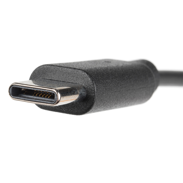
- 1x USB Cable
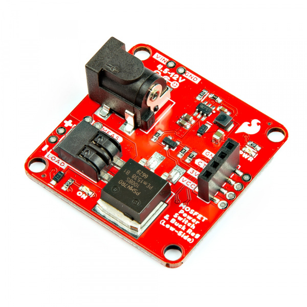
- 1x SparkFun MOSFET Power Switch and Buck Regulator (Low-Side)
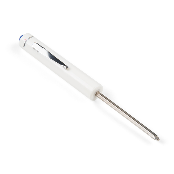
- 1x SparkFun Mini Screwdriver
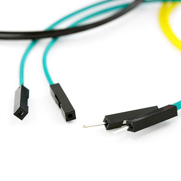
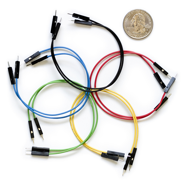
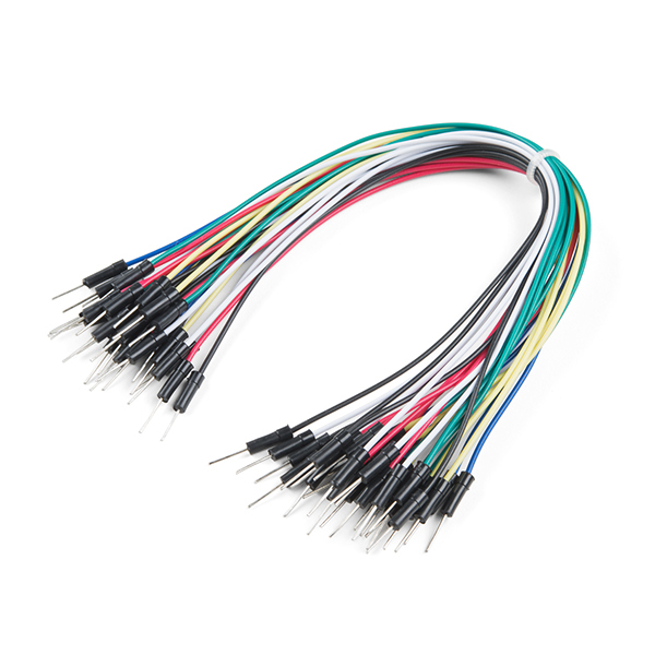
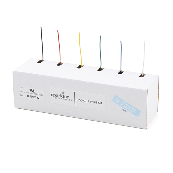
- 1x Pack of Jumper Wires
- 1x High Power Load
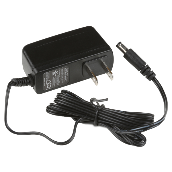
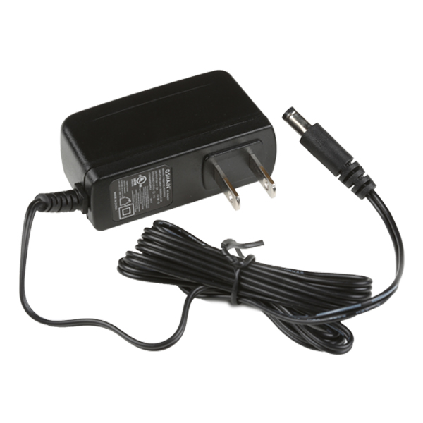
- 1x Wall Adapter
Microcontroller
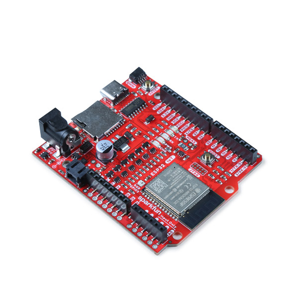
For the scope of the tutorial, we will be using an Arduino microcontroller. In this case, we will be using the SparkFun IoT RedBoard - ESP32. You can use any Arduino microcontroller with digital or PWM pins. Make sure to also include a USB cable that is compatible with your microcontroller.
Tip
The 3.3V output from the MOSFET Power Switch and Buck Regulator (Low-Side) provides another alternative to power microcontrollers that may not be able to accept higher voltages. For example, most of the Thing Plus Development Boards only accept a maximum of 6V at their VIN pin, and they most operate at 3.3V. So this board is especially handy in those use-cases. Additionally, even though the Arduino Pro Mini can accept up to 12V, this will require its onboard linear regulator to work very had to regulate that voltage down to 3.3V. Thus, this MOSFET Power Switch and Buck Regulator (Low-Side) would be the "cooler" choice.
Note
The tutorial focuses on using a microcontroller with Arduino. However, if your microcontroller has a digital or PWM, you can also control the N-channel MOSFET controller as well! You can also use this using a micro:bit with MakeCode or Raspberry Pi's RP2040 microcontroller with MicroPython!
12V LEDs
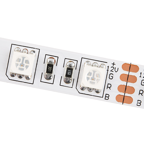
The MOSFET Power Switch and Buck Regulator (Low-Side) can control 12V LEDs. For users with a 12V RGB LED strip, you can control one channel.
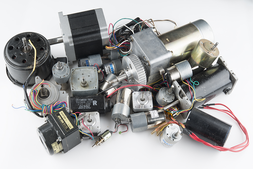
Motors
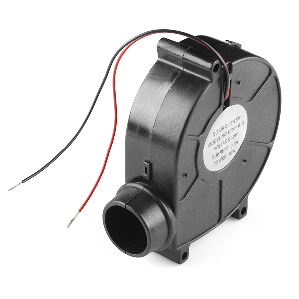
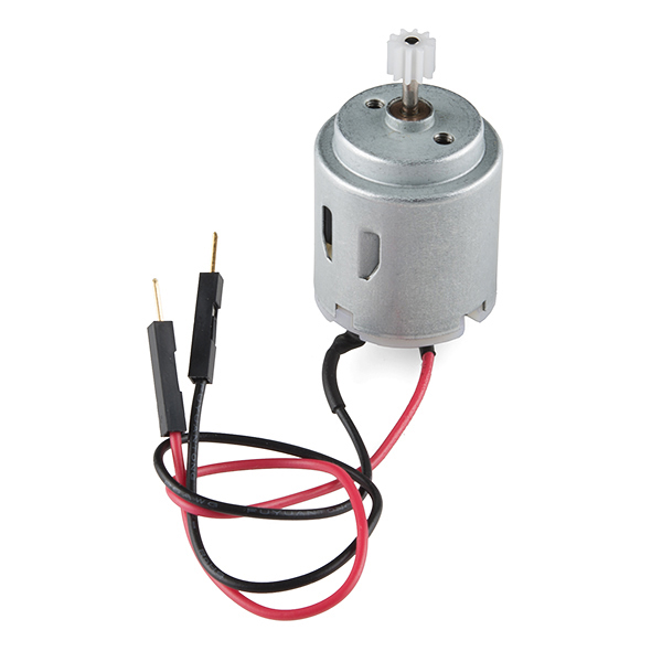
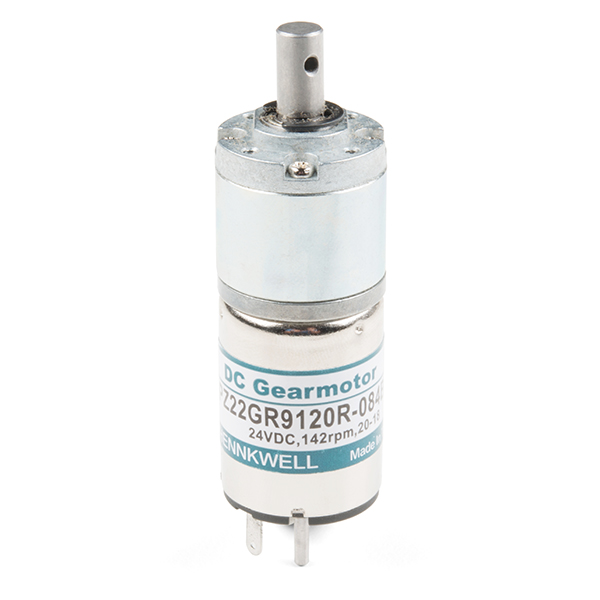
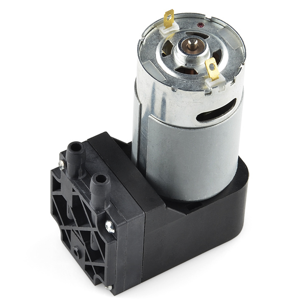
There are a variety of motors with different ratings. Below are a few different motors that you could use for users that just need a motor to spin in one direction.
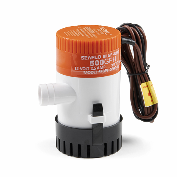
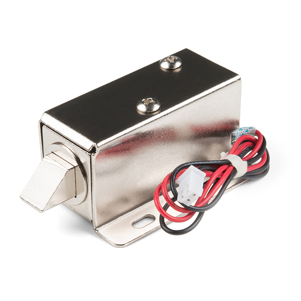
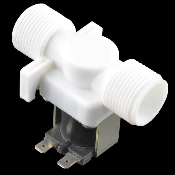
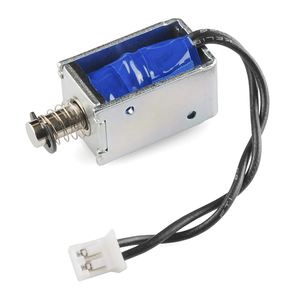
Solenoid
Check below if you need a latching solenoid to lock a box of your secret stash of cookies, solenoid valve to water some plants, or even have the small solenoid tap a glass cup of water! Similar to the motors, each solenoid will have a different rating.
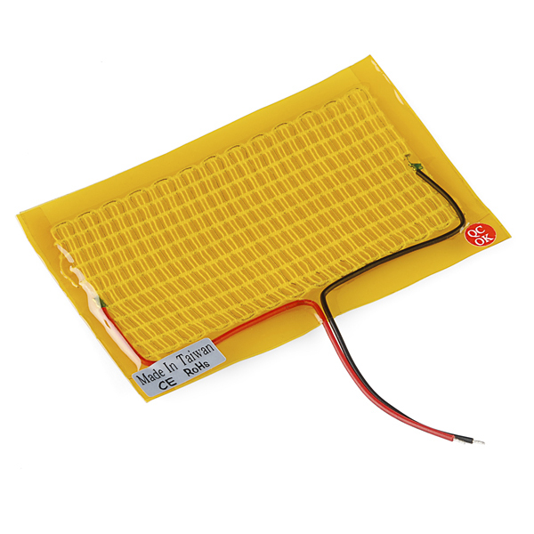
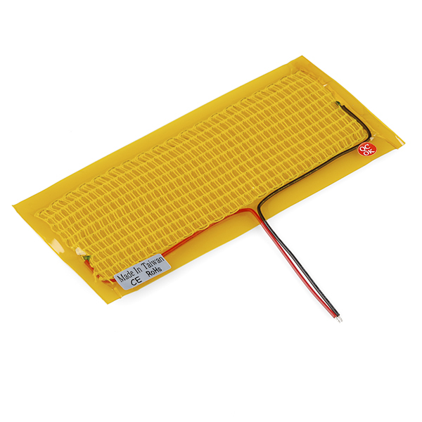
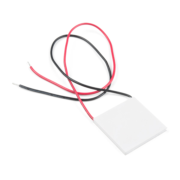
Heating Element
Feeling cold? Try adding a small heating pad to warm up your hands or even a horse bit for an early morning ride! Or maybe you want to make a mini-refrigerator to keep your drinks cool with a thermoelectric cooler.
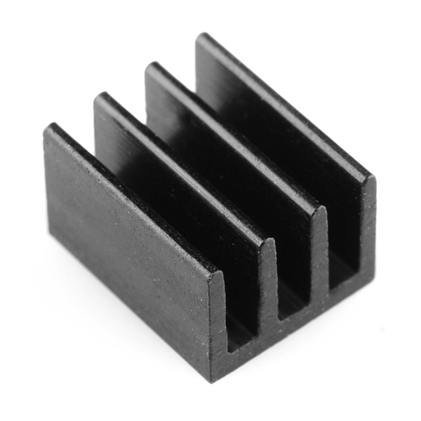
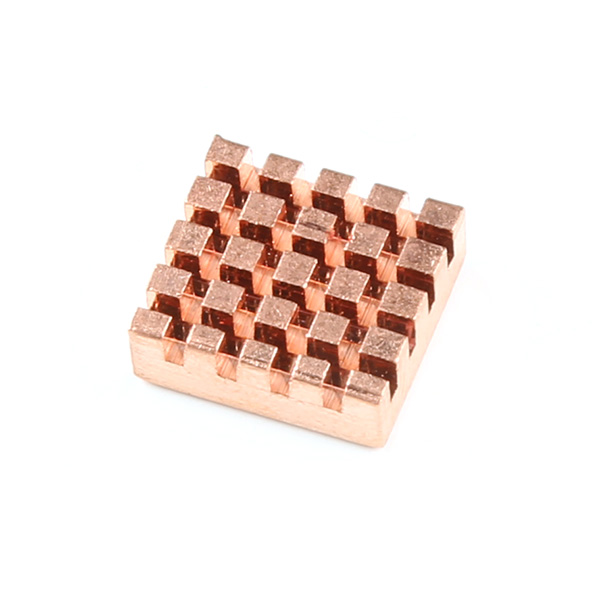
Heatsink
Is your MOSFET getting too hot to the touch? You can add a small heatsink to help dissipate some heat. The small heatsink listed below fits the exposed ground plane on the back of the board. If you need a slightly bigger heat sink, there is also the copper heatsink (note that it's a little bigger than the size of the exposed ground plane). You can also use the copper heatsink with the thermoelectric cooler listed above.
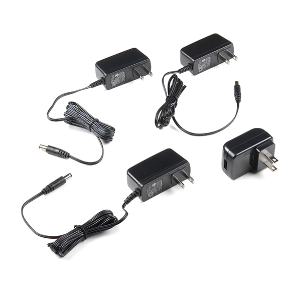
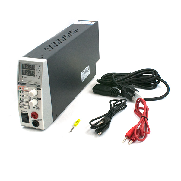
Power Supply
The power supply that you use will depend on your load and project requirements. For example, the small solenoid is rated for 5V while the latching solenoid is rated for 12V. Below are a few power supplies available in SparkFun's catalog. Not sure which power supply that you need? Try grabbing the power supply sample kit!
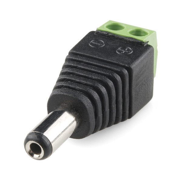
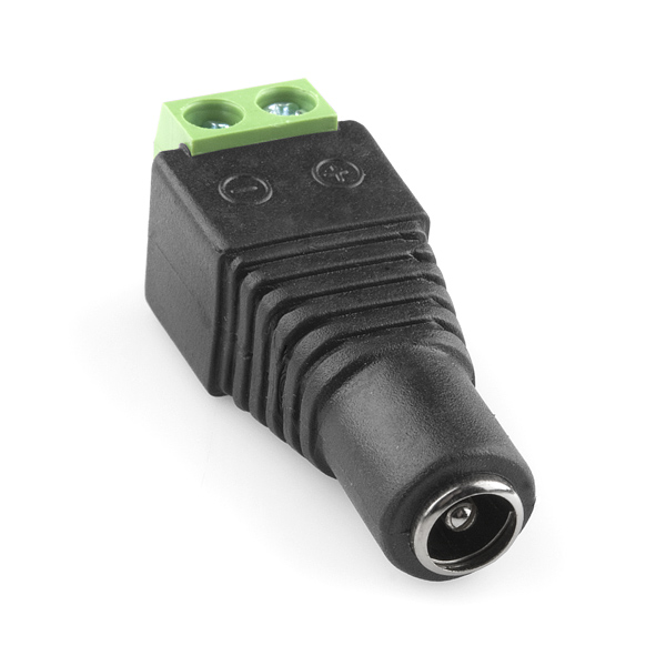
If you decided to connect a few MOSFET Power Switch and Buck Regulators (Low-Side) together using the same power supply, you may want to include the following barrel jack adapters.
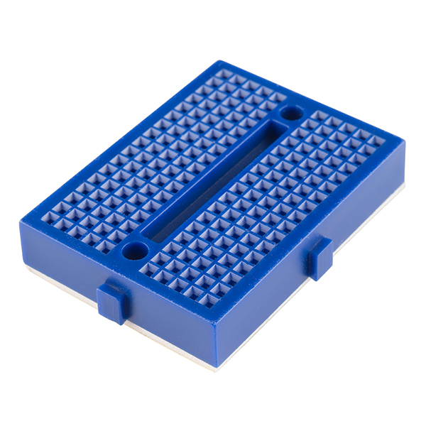
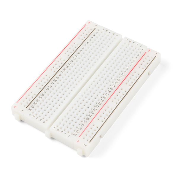
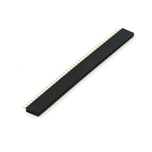
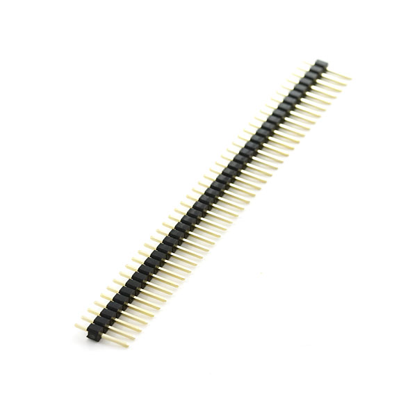
Prototyping Accessories (Optional)
We've designed the board to allow for an easy connection with the rest of the system using M/M jumper wires. Depending on your application, you can solder header pins or you may need an additional breadboard. Below are a few prototyping accessories that you may want to consider.
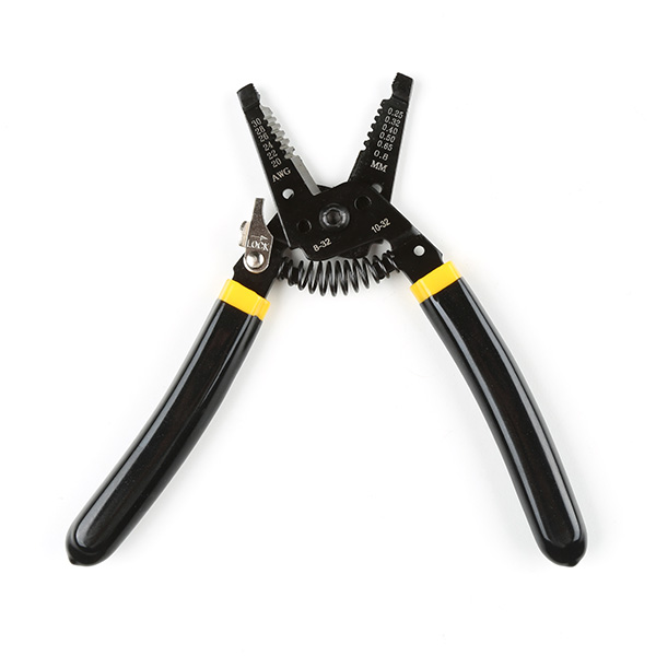
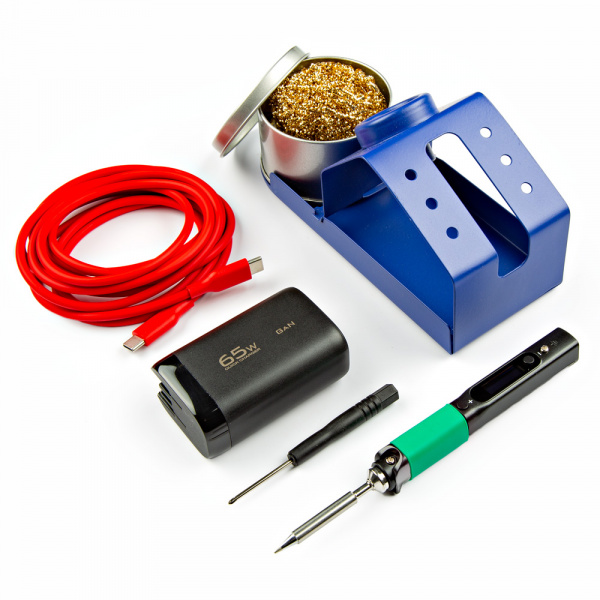
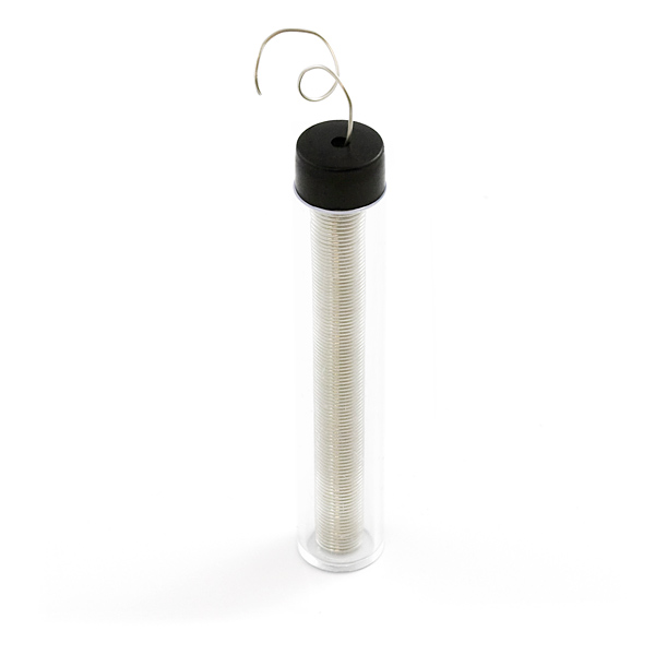
Tools (Optional)
Besides the mini screwdriver, there may be other tools that you may need. For a secure connection, you will need to solder two wires between your microcontroller and the breakout board. This requires some assembly and soldering. You may already have a few of these items but if not, the tools and hardware below help with that assembly.
You Will Also Need
If you decide to do some "magic," try grabbing the following with the squirrel cage blower.
- Ping Pong Ball
Suggested Reading
If you aren’t familiar with the following concepts, we also recommend checking out a few of these tutorials before continuing.


Hardware Overview
In this section, we will highlight the features of the N-channel MOSFET Power Switch and Buck Regulator (Low-Side). For more information about the LMR14203 3.3V buck regulator or PSMN7R0-100BS N-channel MOSFET, make sure to check out the datasheets that are linked in the Resources section.
 |
 |
| Top View | Bottom View |
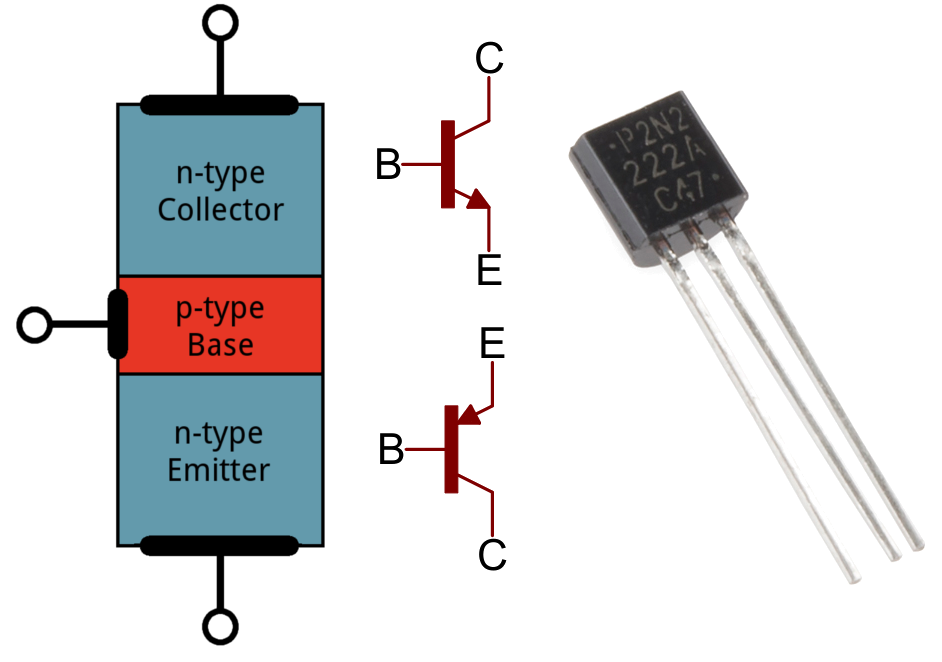
N-Channel MOSFET
The N-channel MOSFET is configured as a low-side switch. On the back of the board, there is a ground plane to aid in heat dissipation. At 12V, 3A the board stays cool (40 °C;) under a continuous load. At 12V, 8.5A with shorter bursts of current (i.e. 5-10 seconds per burst, max current), the board gets toasty (80°C;). You will want to avoid touching the board since it will burn your finger.
 |
 |
| N-Channel MOSFET | Ground Plane Under MOSFET for Heat Dissipation |
Input Voltage
There are two options to connect to the input voltage:
- Barrel Jack — For users with a wall adapter, you could use a 5.5mm x 2.1mm center positive, barrel jack with the recommended input voltage. This is for users that want to easily connect the power supply without the need to solder. Make sure to check the specifications of your wall adapter before connecting since some power supplies have a different polarity.
- PTHs — There is also a pair of pads beside the barrel jack to connect to the input voltage (VIN) and ground (GND). The PTHs are for users that want a more permanent connection and require a smaller profile by soldering wires directly to the PTH. We recommend connecting power from your power supply to this VIN PTH rather than the one by the 1x4 header. The polygon pours connected to the PTH are thicker and can handle the power as opposed to the VCC pin by the 1x4 header.
These connections are broken out as follows:
- VIN — The recommended input voltage is between 4.5V and 12V.
- GND — Common ground or 0V.
 |
| Input Voltage Options Highlighted |
3.3V Regulator Output Voltage
Voltage from the input is brought down to 3.3V/300mA with the buck regulator. This is intended to connect to a microcontroller's 3.3V pin using either the 1x4 header and the PTHs.
 |
| Output Voltage Highlighted |
1x4 Header Connections
On the side of the board, there are two options to connect to ground, control pin, output 3.3V voltage, and input voltage,
- 1x4 female header — Users that have jumper wires with male pins can easily connect to the female headers.
- PTHs — For users that require a more secure connection like the input voltage side, you can also solder to the PTHs as well. As explained earlier, the traces connecting to the VCC on this side is not as big as the one by VIN by the barrel jack.
These connections are broken out as follows:
- GND — Common ground or 0V.
- CTL — Short for control, this pin is connected to the N-channel MOSFET's gate pin and it is active low. There is a pull-up resistor connected to this pin. Users can connect to a jumper wire from this pin to GND to turn on the MOSFET and provide power to the load. Of course, this board was designed to connect to a microcontroller so it can be connected to a digital or PWM pin. Toggling the control pin with the digital pin will turn on and off MOSFET. Using a PWM pin will give you more flexibility to turn on, off, or partially on the load.
- 3V3 — 3.3V output from the buck regulator. This is intended to connect to a microcontroller's 3.3V pin.
- VCC — This pin is connected to the MEAS jumper and VIN. The trace connecting to the pin on the control side is smaller than the polygon pour for VIN. Users can also connect the microcontroller's input voltage to this pin as an alternative to using the 3V3 if their system requires. Just make sure to choose either the 3V3 or VCC to power the microcontroller. Of course, users can also power additional devices on this pin as well.
 |
| 1x4 Header Highlighted |
Load Side
There are two options to connect to the output load side.
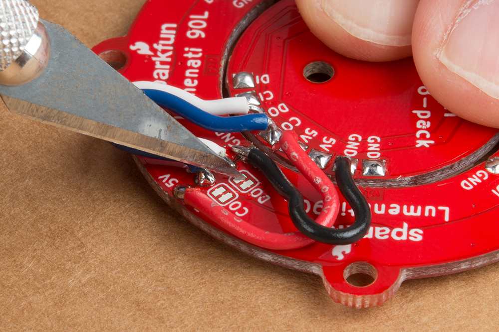
- Poke-Home Connectors — For users that have a stripped wire or jumper wire pins, you can use a ballpoint pen to press down on the tab of the connector to insert a stripped wire or pin into the connector. You can also use a mini screwdriver (Phillips or flat head)
- PTHs — For users that want a permanent connection, you can solder your load directly to the PTHs.
The N-channel MOSFET is configured as a low-side switch: the load is connected to the N-channel MOSFET's drain pin, while the source is connected to ground
The load side connections are broken out as follows:
- VCC (or +) — This pin is for connecting the load's input voltage to the VCC pin.
- LOAD (or −) — This pin is intended for connecting the load's ground to the LOAD pin.
 |
| Load Side Highlighted |
Note
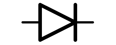
There is also a flyback diode connected to the load side! This component is for loads with motors. When the motor is spinning and suddenly turned off, the magnetic field inside it collapses, generating a voltage spike. This can damage the transistor. These voltage spikes can also happen with solenoids. The image below (taken from Pete's camera!) shows an oscilloscope measuring the nasty voltage spike as soon as the 12V latching solenoid (without a flyback diode) is turned off.
 |
| Voltage without Flyback Diode |
To prevent voltage spikes, we use a "flyback diode," which suppresses the voltage spike. As seen below the voltage is not as dangerous for our N-channel MOSFET.
 |
| Voltage with Flyback Diode |
LEDs
There are two LEDs on the board.
- PWR — The power LED lights up when there is power on the output of the 3.3V buck regulator. This LED can be disabled by cutting the trace on the PWR_LED jumper.
- ON — The ON LED lights up when the control pin is pulled low indicating that there is power applied to the load. This LED can be disabled by cutting the trace on the ON_LED jumper.

|
| LEDs Highlighted |
Jumpers
There are a few jumper pads available on the bottom of the board. For more information on modifying the jumpers, check out our tutorial on working with jumper pads and PCB traces.
- PWR_LED — By default, this jumper is closed. This is connected to the PWR LED and indicates when there is power. Cut this trace to disable the power LED that is connected to 3.3V.
- MEAS — To enable measurements and determine how much current your system is pulling, we've added a NC (normally closed) jumper between the two MEAS PTH pins. By cutting this jumper, the voltage connecting to the 3.3V voltage regulator's input is interrupted. Soldering in male jumper pins or wires into the accompanying holes will give you the ability to insert a current meter and precisely monitor how much current your application is consuming.
- ON_LED — By default, this jumper is closed. This is connected to the ON LED. This LED indicates when the control pin is pulled low and when there is power applied to the load. Cut this trace to disable the ON LED that is connected to the control pin.
 |
| Jumpers Highlighted |
Board Dimensions
The board is 1.50" x 1.50" (38.1mm x 38.1mm), which is slightly bigger than a typical 1.0"x1.0" Qwiic sized board. There are 4x mounting holes by each corner of the board.
 |
| Board Dimensions |
Hardware Hookup
In this section, we'll go over how to connect the MOSFET Power Switch to your system.
Upload Code to the Microcontroller
When uploading code to the IoT RedBoard - ESP32, we will connect a USB C cable. When powering the load, we will want to disconnect the USB cable to avoid conflicting voltages.
 |
Tip
If necessary, you can disconnect the 3.3V jumper wire connecting the MOSFET Power Switch and Buck Regulator to the IoT RedBoard - ESP32. That way you can power the load with the barrel jack while also debugging code when the USB cable is connected to the IoT RedBoard - ESP32.
Control
Note
The tutorial focuses on using a microcontroller with Arduino. However, if your microcontroller has a digital or PWM, you can also control the N-channel MOSFET controller as well! You can also use this using a micro:bit with MakeCode or Raspberry Pi's RP2040 microcontroller with MicroPython!
For prototyping or connecting to the control side, we recommend using a 3.3V development board with header pins already soldered to the board. In this case, we used the IoT RedBoard - ESP32. Depending on how you are controlling the load, you may need a digital or PWM pin. Don't forget to connect power and ground. In this case, we will use 3.3V from the output of the buck regulator. Of course, you could also connect the microcontroller or additional devices to the VCC pin as an alternative. Just make sure to choose one when powering your microcontroller or any additional peripheral device.
| MOSFET Power Switch | IoT RedBoard - ESP32 |
|---|---|
| 3V3 | 3.3V |
| GND | GND |
| CTL | D25 |
Below is a circuit diagram with the MOSFET Power Switch and Buck Regulator Break connecting to the IoT RedBoard - ESP32. Most of the examples will follow this pin connection to control the load. However, there are a few examples that will include additional circuits and a different pin for the control.
 |
Warning
When powering and programming your Arduino, make sure to disconnect power between the MOSFET Power Switch and Arduino to avoid conflicting voltages. Of course you could use a Schottky diode for protection. The caveat is that you will just have a slight voltage drop.
Load
Connect a high voltage device of your choice (e.g. DC motor, solenoid, 12V LED) to the load side (VCC to + and GND to −). You will need a ball point pen to push down on each poke-home connector's tab. A mini screwdriver (Phillips or flat head) will also work as well. As you are pressing down on the tab, insert a stripped wire or jumper wire pin into the socket. Repeat for the other connection.
 |
Below are a few examples. The squirrel cage blower we just inserted the Poke-Home conenctor since the wires were stripped. For the latching solenoid, we used M/M jumper wires between the 2-pin connector and the Poke-Home connector. We used part of a 12V LED strip rather than a full strip.
 |
 |
 |
Tip
Worried about the M/M jumper wire's pins when inserting the Poke-Home connector? There are other M/M jumper wires available. These are lower cost and so you do not have to worry about damaging your premium jumper wires. These were used with the latching solenoid's 2-pin connector.
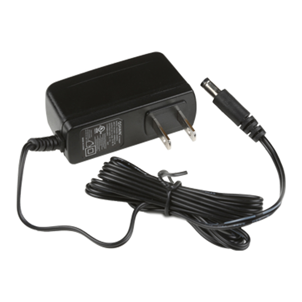
Input Voltage
Grab a compatible wall adapter that is within the recommended voltage range for your project. Make sure that the barrel jack's output is a center-positive. Then insert it into the barrel jack connector.
 |
Connecting to the PTHs
For users that prefer to use the PTHs, we recommending soldering to the connection. You can choose between a combination of header pins and jumper wires, or stripping wire and soldering the wire directly to the board.

Tip
The PTHs are connected to large polygon pours and traces. You may need a larger soldering iron tip, increase the soldering station's temperature, some flux, or leave the soldering tip a little longer in order for the solder to flow better.
Arduino Examples
Arduino
This example assumes you are using the latest version of the Arduino IDE on your desktop. If this is your first time using the Arduino IDE or board add-on, please review the following tutorials.
If you've never connected an CH340 device to your computer before, you may need to install drivers for the USB-to-serial converter. Check out our section on "How to Install CH340 Drivers" for help with the installation.
You will need either a microcontroller's digital or PWM pin to control the N-channel MOSFET Power Switch. Let's check out a few of the examples below to get started!
Example 1: Switching a Load
In this example, we will turn on and off a load using the N-channel MOSFET every few seconds. The load can be a solenoid, DC motor, or a 12V LED.
Parts Needed
Grab the following quantities of each part listed to build this circuit:
- 1x SparkFun IoT RedBoard - ESP32 Development Board
- 1x USB-C Cable
- 3x SparkFun MOSFET Power Switch and Buck Regulator (Low-Side)
- 1x SparkFun Mini Screwdriver
- 3x M/M Jumper Wires
- 1x Squirrel Cage Blower (12V)
- 1x Ping Pong Ball
- 1x 12V Wall Adapter Power Supply
Hardware Hookup
You will need to connect everything as explained earlier. For this particular example, we will use a squirrel cage blower with a motor as shown in the circuit diagram below. Of course, we are using a generic motor in the circuit diagram to represent the squirrel cage blower.
 |
Your setup should look similar to the image below without the power supply.
|
Upload Code
To upload code, insert the USB cable into the IoT RedBoard - ESP32.
Note
This example is similar to the built-in Arduino example. From the menu, select the following: File > Examples > 01.Basics > Blink. You will need to modify the macro (LED_BUILTIN) with a digital pin for your microcontroller. Note that the logic is reversed due to the transistor.
Copy the following code and paste it in the Arduino IDE. If you have not already, select your Board (in this case, the SparkFun ESP32 IoT RedBoard), and associated COM port. Then hit the upload button.
/******************************************************************************
  Example 1: Switching a Load
  Modified By: Ho Yun "Bobby" Chan
  SparkFun Electronics
  Date: October 27th, 2023
  License: MIT. See license file for more information but you can
  basically do whatever you want with this code.

  This example is based on Arduino's blink example. It has been modified
  so that it can be used for the SparkFun IoT RedBoard - ESP32 but it can be
  used with any Arduino that has a digital pin. The load (solenoid, DC motor,
  or 12V LED) will toggle on and off every 5 seconds.

  Users can also open the Serial Monitor at 115200 to check on
  the status of the load for debugging.

  Feel like supporting open source hardware?
  Buy a board or component from SparkFun!

      SparkFun IoT RedBoard - ESP32 Development Board:            https://www.sparkfun.com/products/19177
      SparkFun MOSFET Power Switch and Buck Regulator (Low-Side): https://www.sparkfun.com/products/23979
      Solenoid - 12V (Latch / Lock):                              https://www.sparkfun.com/products/15324
      Hobby Motor - Gear:                                         https://www.sparkfun.com/products/11696
      Blower - Squirrel Cage (12V):                               https://www.sparkfun.com/products/11270
      12V LED RGB Strip - Bare (1m):                              https://www.sparkfun.com/products/12021
      Wall Adapter 12V/600mA, (Barrel Jack):                      https://www.sparkfun.com/products/15313

  Distributed as-is; no warranty is given.
******************************************************************************/

//define a pin for the load, you'll need to adjust this
//depending on the microcontroller that you using
const int loadPin = 25;

// the setup function runs once when you press reset or power the board
void setup() {

  //Initialize Serial for Debugging if there is no built-in LED
  Serial.begin(115200);
  Serial.println("Toggling a Load!");

  // initialize digital pin as an output.
  pinMode(loadPin, OUTPUT);
  digitalWrite(loadPin, HIGH);  // turn the LOAD off (HIGH is the voltage level)
  Serial.println("OFF");

}  //END SETUP


// the loop function runs over and over again forever
void loop() {

  digitalWrite(loadPin, LOW);  // turn the LOAD ON (LOW is the voltage level)
  Serial.println("ON");
  delay(5000);  // wait for a few seconds

  digitalWrite(loadPin, HIGH);  // turn the LOAD OFF by making the voltage HIGH
  Serial.println("OFF");
  delay(5000);  // wait for a few seconds

}  //END LOOP
What You Should See
Once the code has uploaded, Once the code has uploaded, disconnect the USB cable from the IoT RedBoard - ESP32. Then insert the barrel jack from a power supply to the MOSFET Power Switch and Buck Regulator's barrel jack connector. In this case, we used a 12V wall adapter power supply.
The load will be powered on for 5 seconds before turning back off for another 5 seconds. Compared to the original blink example, the delay is longer to allow enough time for the load to turn on. This will loop forever until you remove power. If necessary, disconnect the 3.3V jumper wire from the IoT RedBoard - ESP32, reconnect the USB cable, and open the Arduino Serial Monitor at 115200 baud for debugging purposes.
 |
Try adjusting the delay or even adding a Qwiic sensor with some code to trigger a load!
Example 2: Toggling a Load with a Button
In this example, we will turn on and off a load using the N-channel MOSFET with a button press. The load can be a solenoid, DC motor, or a 12V LED.
Parts Needed
Grab the following quantities of each part listed to build this circuit:
- 1x SparkFun IoT RedBoard - ESP32 Development Board
- 1x USB-C Cable
- 3x SparkFun MOSFET Power Switch and Buck Regulator (Low-Side)
- 1x SparkFun Mini Screwdriver
- 7x M/M Jumper Wires
- 1x Mini Breadboard
- 1x Momentary Push Button
- 1x Latching Solenoid (12V)
- 1x 12V Wall Adapter Power Supply
Hardware Hookup
You will need to connect everything as explained earlier (with the exception of the momentary push button). For this particular example, we will use a latching solenoid and add a momentary pushbutton as shown in the circuit diagram below.
 |
Your setup should look similar to the image below without the power supply.
 |
Upload Code
To upload code, insert the USB cable into the IoT RedBoard - ESP32.
Copy the following code and paste it in the Arduino IDE. If you have not already, select your Board (in this case, the SparkFun ESP32 IoT RedBoard), and associated COM port. Then hit the upload button.
/******************************************************************************
  Example 2: Toggling a Load with a Button
  Written By: Ho Yun "Bobby" Chan
  SparkFun Electronics
  Date: October 27th, 2023
  License: MIT. See license file for more information but you can
  basically do whatever you want with this code.

  This example toggles the load (solenoid, DC motor, or 12V LED)
  based on a button press. The status LED will light up at the
  same time. This example checks to see if the momentary button
  is still being pressed and will only toggle the load when the
  button after releasing and pressing down on the button again.

  The example was tested on the SparkFun IoT RedBoard - ESP32.
  However, it can be used with any Arduino that has a digital pin.
  Users can also open the Serial Monitor at 115200 to check on
  the status of the button for debugging.

  Feel like supporting open source hardware?
  Buy a board or component from SparkFun!

      SparkFun MOSFET Power Switch and Buck Regulator (Low-Side): https://www.sparkfun.com/products/23979
      SparkFun IoT RedBoard - ESP32 Development Board:            https://www.sparkfun.com/products/19177
      Solenoid - 12V (Latch / Lock):                              https://www.sparkfun.com/products/15324
      Hobby Motor - Gear:                                         https://www.sparkfun.com/products/11696
      Blower - Squirrel Cage (12V):                               https://www.sparkfun.com/products/11270
      12V LED RGB Strip - Bare (1m):                              https://www.sparkfun.com/products/12021
      Wall Adapter 12V/600mA, (Barrel Jack):                      https://www.sparkfun.com/products/15313

  Distributed as-is; no warranty is given.
******************************************************************************/

// pushbutton 1 pin
const int button1Pin = 4;
boolean button1State = false;
boolean prevbutton1State = false;
boolean currentbutton1State = false;

//define a pin for the load, you'll need to adjust this
//depending on the microcontroller that you using
const int loadPin = 25;
boolean mode = false;  //mode to toggle load, set to off at the start

const int ledPin = 18;  // built-in LED pin for IoT RedBoard - ESP32
                        /*Note: Users can also use the macro LED_BUILTIN. Just make sure to comment the line above
                        and replace "ledPIN" with "LEDBUILTIN"*/


void setup() {

  //Initialize Serial for Debugging if there is no built-in LED
  Serial.begin(115200);
  Serial.println("Toggling a Load with a Button!");

  // Set up the pushbutton pin to be an input with a pull-up resistor:
  pinMode(button1Pin, INPUT_PULLUP);

  // Set up the load pin to be an output and turn it off:
  pinMode(loadPin, OUTPUT);
  digitalWrite(loadPin, HIGH);

  //Set up built-in LED as an OUTPUT and ensure that it is off as well:
  pinMode(ledPin, OUTPUT);
  digitalWrite(ledPin, LOW);

  Serial.println("OFF");

}  //END SETUP


void loop() {

  button1State = digitalRead(button1Pin);

  //if button is pressed, it will be pulled low
  if (button1State == LOW) {
    currentbutton1State = true;  // button has been pressed once

    if (prevbutton1State != currentbutton1State) {  //check to see if button is still being pressed

      if (mode == false) {
        mode = true;
      } else {
        mode = false;
      }

      if (mode == true) {

        digitalWrite(loadPin, LOW);
        digitalWrite(ledPin, HIGH);
        Serial.println("ON");

      } else {

        digitalWrite(loadPin, HIGH);
        digitalWrite(ledPin, LOW);
        Serial.println("OFF");
      }

      delay(500);  //add small delay, you may need to have a bigger delay for button debouncing

    } else {  //do nothing because finger is still on button
    }


    prevbutton1State = currentbutton1State;  //update button1 state
  }
  //button has not been pressed, it will be high
  else {

    currentbutton1State = false;
    prevbutton1State = currentbutton1State;  //update button1 state
  }


}  //END LOOP
What You Should See
Once the code has uploaded, disconnect the USB cable from the IoT RedBoard - ESP32. Then insert the barrel jack from a power supply to the MOSFET Power Switch and Buck Regulator's barrel jack connector. In this case, we used a 12V wall adapter power supply.
The load will be powered on as soon as the button is pressed. Releasing and pressing the button again will turn the load off. The built-in LED will light up every time the load is turned on. Of course, there is also a built-in LED on the MOSFET Power Switch and Buck Regulator that will light up whenever power is applied to the load as well. If necessary, disconnect the 3.3V jumper wire from the IoT RedBoard - ESP32, reconnect the USB cable, and open the Arduino Serial Monitor at 115200 baud for debugging purposes.
 |
Even though this example used a button to toggle a latching solenoid, you can also use this example to control a DC motor or 12V LED! You can also try using the Qwiic RFID with an RFID tag instead of a button to turn the solenoid on. Just make sure to adjust the example code should you decide to use something else other than a button to contorl your load.
Example 3: Fading
In this example, we will slowly turn on the load and then slowly turn it off using the N-channel MOSFET. This example is better with a DC motor and 12V LED. You will typically want the solenoid to be fully turned on/off.
Parts Needed
Grab the following quantities of each part listed to build this circuit:
- 1x SparkFun IoT RedBoard - ESP32 Development Board
- 1x USB-C Cable
- 3x SparkFun MOSFET Power Switch and Buck Regulator (Low-Side)
- 1x SparkFun Mini Screwdriver
- 3x M/M Jumper Wires
- 1x 12V RGB LED Strip
- 1x 12V Wall Adapter Power Supply
Hardware Hookup
You will need to connect everything as explained earlier. For this particular example, we will use one channel from a 12V RGB LED strip as shown in the circuit diagram below.
 |
Note
Notice that we are using pin 16 to fade the red channel instead of pin 25 on the IoT RedBoard - ESP32.
Your setup should look similar to the image below without the power supply.
|
Upload Code
To upload code, insert the USB cable into the IoT RedBoard - ESP32.
Note
This example is similar to the built-in Arduino example. From the menu, select the following: File > Examples > 03.Analog > Fading. You will need to modify the defined pin with a PWM pin for your microcontroller. Note that the logic is reversed due to the transistor.
Copy the following code and paste it in the Arduino IDE. If you have not already, select your Board (in this case, the SparkFun ESP32 IoT RedBoard), and associated COM port. Then hit the upload button.
/******************************************************************************
      Example 3: Fading
      Modified By: Ho Yun "Bobby" Chan
      SparkFun Electronics
      Date: October 27th, 2023
      License: MIT. See license file for more information but you can
      basically do whatever you want with this code.

      This example is based on Arduino's fade example. It has been modified
      so that it can be used for the SparkFun IoT RedBoard- ESP32 but it can be
      used with any Arduino that has a PWM pin. The load (DC motor,
      or 12V LED) will slowly turn on and off. This code will be more useful for
      users connecting a DC motor or nonaddressable LED so that you can partially
      turn on/off the load.

      Users can also open the Serial Monitor at 115200 to check on
      the status of the button for debugging.

      Feel like supporting open source hardware?
      Buy a board or component from SparkFun!

          SparkFun MOSFET Power Switch and Buck Regulator (Low-Side): https://www.sparkfun.com/products/23979
          SparkFun IoT RedBoard - ESP32 Development Board:            https://www.sparkfun.com/products/19177
          Hobby Motor - Gear:                                         https://www.sparkfun.com/products/11696
          Blower - Squirrel Cage (12V):                               https://www.sparkfun.com/products/11270
          12V LED RGB Strip - Bare (1m):                              https://www.sparkfun.com/products/12021
          Wall Adapter 12V/600mA, (Barrel Jack):                      https://www.sparkfun.com/products/15313

      Distributed as-is; no warranty is given.
    ******************************************************************************/

int loadPin = 16;

// the setup function runs once when you press reset or power the board
void setup() {

  //Initialize Serial for Debugging if there is no built-in LED
  Serial.begin(115200);
  Serial.println("Analog fade in and out to slowly turn on/off load!");

  // Set up the load pin to be an output and turn it off:
  pinMode(loadPin, OUTPUT);
  analogWrite(loadPin, 255);

  Serial.println("OFF");

}  //END SETUP


// the loop function runs over and over again forever
void loop() {

  Serial.println("<===== FADE IN =====>");
  // fade in from min to max in increments of 5 points:
  for (int fadeValue = 255; fadeValue >= 0; fadeValue -= 5) {
    // sets the value (range from 0 to 255):
    analogWrite(loadPin, fadeValue);
    // wait for 30 milliseconds to see the dimming effect
    delay(30);

    Serial.println(fadeValue);
  }

  Serial.println("<===== FADE OUT =====>");
  // fade out from max to min in increments of 5 points:
  for (int fadeValue = 0; fadeValue <= 255; fadeValue += 5) {
    // sets the value (range from 0 to 255):
    analogWrite(loadPin, fadeValue);
    // wait for 30 milliseconds to see the dimming effect
    delay(30);

    Serial.println(fadeValue);
  }

}  //END LOOP
What You Should See
Once the code has uploaded, disconnect the USB cable from the IoT RedBoard - ESP32. Then insert the barrel jack from a power supply to the MOSFET Power Switch and Buck Regulator's barrel jack connector. In this case, we used a 12V wall adapter power supply.
The load will slowly turn on and slowly turn off. This will loop forever until power is removed from the board. If necessary, disconnect the 3.3V jumper wire from the IoT RedBoard - ESP32, reconnect the USB cable, and open the Arduino Serial Monitor at 115200 baud for debugging purposes.
 |
While this example was used to turn on one channel of a 12V RGB LED strip, you could also use this example with a DC motor. Try using a potentiometer (or any 3.3V analog sensor) with the map() function to adjust the speed of the motor.
Example 4: 12V RGB LED Strip
In this example, we will control all three channels of the RGB LED strip. Since we've already hooked up a 12V RGB LED strip before, we will also a circuit with a potentiometer to cycle between each color and a photoresistor to turn on the LEDs whenever the light is below a certain light level. The following example code is based on the SparkFun Inventor's Kit v4.1 Night Light example.
Parts Needed
Grab the following quantities of each part listed to build this circuit:
- 1x SparkFun IoT RedBoard - ESP32 Development Board
- 1x USB-C Cable
- 3x SparkFun MOSFET Power Switch and Buck Regulator (Low-Side)
- 1x SparkFun Mini Screwdriver
- 19x M/M Jumper Wires*
- 1x Breadboard
- 1x 10kΩ Potentiometer with Knob
- 1x Mini Photocell
- 1x 10kΩ Resistor
- 1x 12V RGB LED Strip
- 1x DC Barrel Jack Adapter - Male
- 3x DC Barrel Jack Adapter - Female
- 1x 12V Wall Adapter
* Note
You will need a minimum of 19x M/M jumper wires. Six jumper wires were stripped wires that connect the barrel jacks together for power and reference ground.
Hardware Hookup
For this particular example, we will use three channels from a 12V RGB LED strip while also including a similar circuit from the SparkFun Inventor's Kit v4.1. The circuit diagram is shown below.
 |
Note
When testing the non-addressable LED strip, the pin labeled "G" was actually blue and the "B" was actually green. Depending on the manufacturer, the label may vary. Try testing the LED strip out with a power supply to determine if the letter represents the color.
Keep in mind that instead of the RedBoard with ATmega328P, we are using the IoT RedBoard with ESP32. Since the hardware is different, the following code was modified:
- analog and PWM pins were redefined in the example code
- threshold was modified due to the ADC's higher resolution
- logic is reversed due to the transistors
Danger
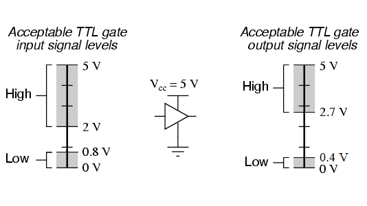
The IoT RedBoard with ESP32 has a system voltage of 3.3V. Thus, the logic levels is 3.3V instead of 5V on the RedBoard with ATmega328P. Thus, the analog reference voltage for the potentiometer and photoresistor is 3.3V. Make sure you are using 3.3V!
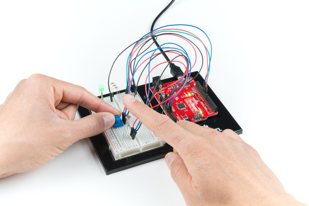
Your setup should look similar to the image below without the power supply.
 |
Upload Code
To upload code, insert the USB cable into the IoT RedBoard - ESP32.
Copy the following code and paste it in the Arduino IDE. If you have not already, select your Board (in this case, the SparkFun ESP32 IoT RedBoard), and associated COM port. Then hit the upload button.
/*
  12V RGB LED Nightlight Example

  Turns an 12V RGB strip LED on or off based on the light level read by a photoresistor.
  Change colors by turning the potentiometer. This example is based off the SparkFun
  Inventor's Kit v4.2 RGB Night-Light Example:

      https://learn.sparkfun.com/tutorials/sparkfun-inventors-kit-experiment-guide---v41

  Note that instead of the RedBoard with ATmega328P, we are using the IoT RedBoard with ESP32.
  Since the hardware is different, the following code was modified:

      - analog and PWM pins were redifined
      - threshold was modified due to the ADC's higher resolution
      - logic is reversed due to the transistors

  WARNING: Since the IoT RedBoard with ESP32 has a system voltage of 3.3V, the logic levels
  is 3.3V instead of 5V on the RedBoard with ATmega328P. Thus, the analog reference voltage
  for the potentiometer and photoresistor is 3.3V. Make sure you are using 3.3V!

  This sketch was written by SparkFun Electronics, with lots of help from the Arduino community.
  This code is completely free for any use.

*/

int photoresistor = A4;          //variable for storing the photoresistor value
int potentiometer = A5;          //this variable will hold a value based on the position of the knob
int threshold = 3000;            //if the photoresistor reading is lower than this value the light will turn on
                                 /*Note: The ESP32's ADC resolution is bigger. The max is 4095. In a bright room
                                 with your finger covering the sensor, the threshold was about 3000. In a dimly
                                 lit room, the threshold was about 1000. You will need to adjust this value when
                                 installing it in a room. Just make sure to make it a little more than the thresholed
                                 of the room. Try adding a button and some code  to save the threshold value! */

//LEDs are connected to these pins
int RedPin = 16;
int GreenPin = 17;
int BluePin = 25;

void setup() {
  Serial.begin(115200);           //start a serial connection with the computer
  Serial.println("12V RGB LED Strip Nightlight!");

  //set the LED pins to output
  pinMode(RedPin, OUTPUT);
  pinMode(GreenPin, OUTPUT);
  pinMode(BluePin, OUTPUT);

} //END SETUP

void loop() {

  photoresistor = analogRead(A4);         //read the value of the photoresistor
  potentiometer = analogRead(A5);         //read the value of the potentiometer

  Serial.print("Photoresistor value:");
  Serial.print(photoresistor);          //print the photoresistor value to the serial monitor
  Serial.print("  Potentiometer value:");
  Serial.println(potentiometer);          //print the potentiometer value to the serial monitor

  if (photoresistor < threshold) {        //if it's dark (the photoresistor value is below the threshold) turn the LED on
    //These nested if statements check for a variety of ranges and
    //call different functions based on the current potentiometer value.
    //Those functions are found at the bottom of the sketch.

    /*Note: We divided 4095 by 7 colors and had a window of about 585. For users
            Adding more colors, try dividing 4095 by the total number and adjust
            eac condition statement*/

    if (potentiometer > 0 && potentiometer <= 585)
      red();
    if (potentiometer > 585 && potentiometer <= 1170)
      orange();
    if (potentiometer > 1170 && potentiometer <= 1755)
      yellow();
    if (potentiometer > 1755 && potentiometer <= 2340)
      green();
    if (potentiometer > 2340 && potentiometer <= 2925)
      cyan();
    if (potentiometer > 2925 && potentiometer <= 3510)
      blue();
    if (potentiometer > 3510)
      magenta();
  }
  else {                                //if it isn't dark turn the LED off

    turnOff();                            //call the turn off function

  }

  delay(100);                             //short delay so that the printout is easier to read

} //END LOOP

void red () {

  //set the LED pins to values that make red
  analogWrite(RedPin, 0);
  analogWrite(GreenPin, 255);
  analogWrite(BluePin, 255);
}
void orange () {

  //set the LED pins to values that make orange
  analogWrite(RedPin, 0);
  analogWrite(GreenPin, 128);
  analogWrite(BluePin, 255);
}
void yellow () {

  //set the LED pins to values that make yellow
  analogWrite(RedPin, 0);
  analogWrite(GreenPin, 0);
  analogWrite(BluePin, 255);
}
void green () {

  //set the LED pins to values that make green
  analogWrite(RedPin, 255);
  analogWrite(GreenPin, 0);
  analogWrite(BluePin, 255);
}
void cyan () {

  //set the LED pins to values that make cyan
  analogWrite(RedPin, 255);
  analogWrite(GreenPin, 0);
  analogWrite(BluePin, 0);
}
void blue () {

  //set the LED pins to values that make blue
  analogWrite(RedPin, 255);
  analogWrite(GreenPin, 255);
  analogWrite(BluePin, 0);
}
void magenta () {

  //set the LED pins to values that make magenta
  analogWrite(RedPin, 0);
  analogWrite(GreenPin, 255);
  analogWrite(BluePin, 0);
}
void turnOff () {

  //set all three LED pins to 0 or OFF
  analogWrite(RedPin, 255);
  analogWrite(GreenPin, 255);
  analogWrite(BluePin, 255);
}
What You Should See
Once the code has uploaded, disconnect the USB cable from the IoT RedBoard - ESP32. Then insert the barrel jack from a power supply to the MOSFET Power Switch and Buck Regulator's barrel jack connector. In this case, we used a 12V wall adapter power supply.
The MOSFET Power Switch & Buck Regulator with the wall adapter. Cover the photoresistor with your finger (or just turn off the lights in the room) and turn the potentiometer. You should notice the colors cycling through as the potentiometer is within certain ranges. You will probably want to disconnect the 3.3V jumper wire from the IoT RedBoard - ESP32, reconnect the USB cable, and open the Arduino Serial Monitor at 115200 baud for debugging purposes. That way you can view the serial data and adjust the threshold value based on the lighting in the room.
 |
Now that we have ported the example from the RedBoard Qwiic with an ATmega328P to the RedBoard IoT Development Board - ESP32, try adjusting the condition statement with the potentiometer to add additional colors. Or even writing some code save the threshold value whenever a button is pressed down. You can also try to take advantage of the ESP32's wireless capabilities and adjust the color of the LED strip based on the weather.
Troubleshooting
General Troubleshooting Help
Note
Not working as expected and need help?
If you need technical assistance and more information on a product that is not working as you expected, we recommend heading on over to the SparkFun Technical Assistance page for some initial troubleshooting.
If you don't find what you need there, the SparkFun Forums are a great place to find and ask for help. If this is your first visit, you'll need to create a Forum Account to search product forums and post questions.
Resources
Now that you've successfully got your SparkFun MOSFET Power Switch and Buck Regulator (Low-Side) up and running, it's time to incorporate it into your own project! For more information, check out the resources below: