Hardware Hookup
Connecting via PTH
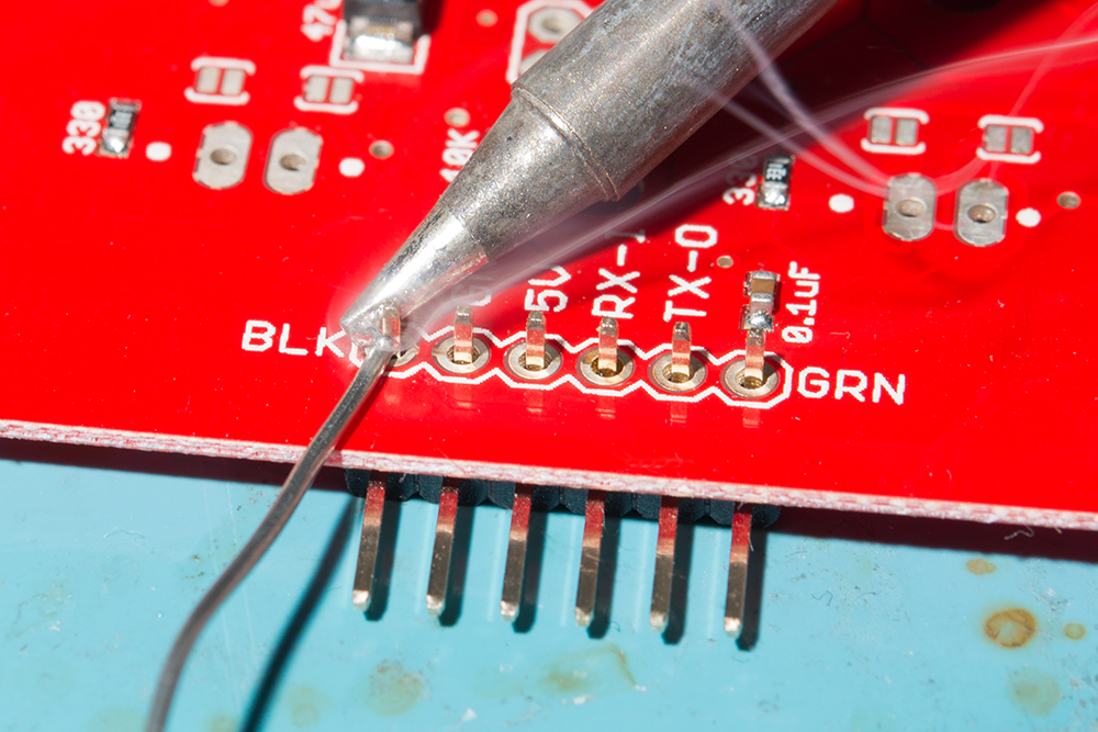
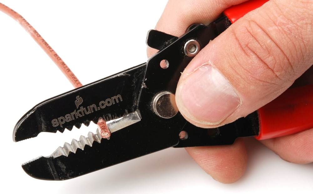
For temporary connections to the PTHs, you could use IC hooks to test out the pins. However, you'll need to solder headers or wires of your choice to the board for a secure connection. You can choose between a combination of header pins and jumper wires, or stripping wire and soldering the wire directly to the board.
For the scope of this tutorial, we will use right angle, male headers. Insert the right angle headers on the top side and solder the header pins from the bottom. Of course, you can also insert the right angle header so that the pins face toward the multiplexors similar to Peter's demo video.
| Magnetic Imaging Tile Pinout |
SAMD21 Pinout (i.e. RedBoard Turbo, SAMD21 Mini, etc.) |
Teensy Pinout (i.e. Teensy v3.1, v3.5, v4.0, v4.1, etc.) |
SAMD51 Pinout (i.e. SAMD51 Thing Plus, etc.) |
|---|---|---|---|
| GND | GND | GND | GND |
| OUT | A1 | A1 | A1 |
| SCK | 13 | 13 | 24 |
| MISO | 12 | 12 | 22 |
| CS | 10 | 10 | 10 |
| CLR | 8 | 8 | 5 |
| CLK | 9 | 9 | 9 |
| 3.3V | 3V3 | 3.3V | 3V3 |
Note
If you are using a development board with updated SPI terminology, MISO may be labeled as POCI.
We will be using the RedBoard Turbo with female headers already installed on the board. For users that are using a different board, now would be a good time to solder headers or wires to the board. Below is an example with female headers soldered on the SAMD51 Thing Plus. Additionally, there are stackable headers soldered on the SAMD21 Mini Breakout so that the board can be inserted into a breadboard.
Connecting a Micrcontroller to the Magnetic Imaging Tile
We recommend using a microcontroller with sufficient RAM. While the example code can compile and function with Arduinos with an ATmega328P, the frames are limited. For the scope of the tutorial, we used a SAMD21. Of course, users can also use a Teensy and ChipKit as well.
Below is the Fritzing diagram of the RedBoard Turbo - SAMD21 connected to the Magnetic Imaging Tile.
After soldering headers to the Magnetic Imaging Tile, wire the board to the RedBoard Turbo using jumper wires. Then connect a micro-b USB cable to power and program the RedBoard Turbo.
You can also connected any SAMD21 to the Magnetic Imaging Tile. Below shows a Fritzing diagram of the SAMD21 Mini Breakout connected to the Magnetic Imaging Tile. When using other development boards, you may need to solder additional headers or wires to the board. Depending on the microcontroller, you may also need to redefine the pins in the Arduino example code in order to properly connect to the SPI port.
After soldering headers (or wires) on your microcontroller and Magnetic Imaging Tile, wire the boards together. The connect a micro-b USB cable to power and program the SAMD21 Mini Breakout.


