Introduction
The SparkFun SARA-R5 LTE GNSS Function Board is a robust development tool for u-blox's impressive SARA-R510M8S module. The SARA-R510M8S combines u-blox's UBX-R5 cellular chipset with their M8 GNSS receiver chipset to provide a 5G-Ready wireless IoT device complete with positioning data all on a single chip. As an asset tracker, the LTE GNSS Function Board offers Secure Cloud LTE-M communication for multi-regional use and has an integrated u-blox M8 GNSS receiver for accurate positioning information.

The UBX-R5 chipset supports many different forms of data communication from full TCP/IP sockets and packet switched data, through HTTP Get/Put/Post, FTP (the SARA has a built-in file system), or ping to good old SMS text messaging! The built-in u‑blox M8 GNSS receiver provides accurate and reliable positioning with a separate GNSS antenna interface for an external antenna. Both the GNSS antenna and LTE connections are made via a pair of u.FL connectors. A nano SIM card slot is also included as well.
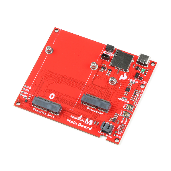
Utilizing our handy M.2 MicroMod connector, no soldering is required to connect it to your system. Simply match up the key on your processor and function board's beveled edge connector to their respective key on the M.2 connector, then secure them to the Main Board with screws.
This Function Board provides access to the UART (default configuration) with a Processor Board. The USB pins are also broken out to a USB-C connector for diagnostic purposes. Status LEDs are included for 3.3V, Ring Indicator, LTE ON, and LTE Network Indicator. A button is included for LTE Power On.
Required Materials
To follow along with this tutorial, you will need the following materials. You may not need everything though depending on what you have. Add it to your cart, read through the guide, and adjust the cart as necessary.
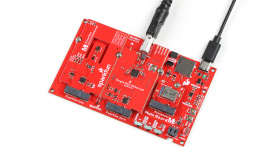
- 1x SparkFun MicroMod - Single Board [DEV-20748]
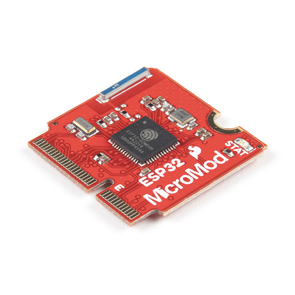
- 1x SparkFun MicroMod ESP32 Processor [WRL-16781]
- There are a variety of MicroMod Processor Boards available. However, we recommend using the ESP32, Artemis, and SAMD51 Processor Boards as these were tested to work with the SARA-R5. For the scope of this tutorial, we will be using the ESP32 Processor Board. The caveat when using the ESP32 Processor Board is that you will need to configure the pin that is connected to the voltage regulator's enable pin. This pin is used to upload code and when the ESP32 boots up. After uploading code and/or when the ESP32 has finished booting up, you will need to configure the pin as an input pullup in the
setup().
- There are a variety of MicroMod Processor Boards available. However, we recommend using the ESP32, Artemis, and SAMD51 Processor Boards as these were tested to work with the SARA-R5. For the scope of this tutorial, we will be using the ESP32 Processor Board. The caveat when using the ESP32 Processor Board is that you will need to configure the pin that is connected to the voltage regulator's enable pin. This pin is used to upload code and when the ESP32 boots up. After uploading code and/or when the ESP32 has finished booting up, you will need to configure the pin as an input pullup in the
- 1x SparkFun LTE GNSS Function Board - SARA-R5 [DEV-18431]
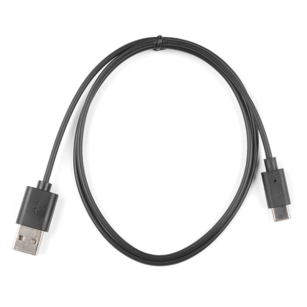
- 1x USB-C cable
- Our USB 2.0 A to C Cable [CAB-15092] will do nicely
- Our USB 3.1 A to C Cable [CAB-14743] is a good choice too
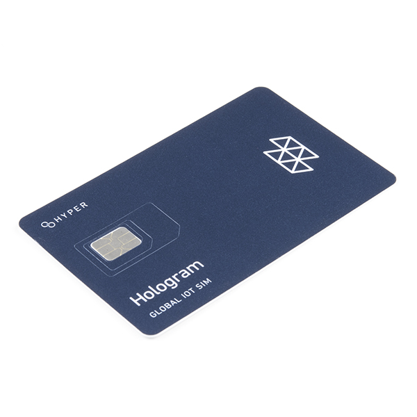
- 1x SIM Card*
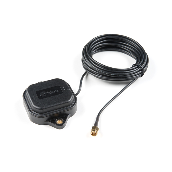
- 1x GNSS Multi-Band Magnetic Mount Antenna - 5m (SMA) [GPS-15192]
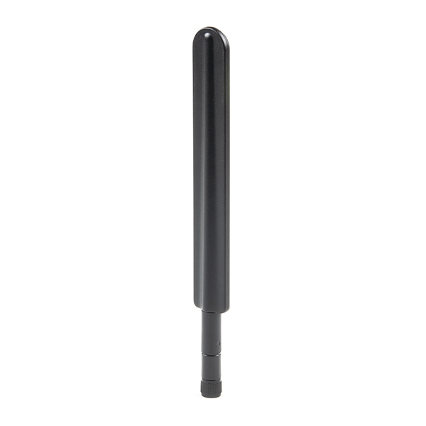
- 1x LTE Hinged External Antenna - 698MHz-2.7GHz, SMA Male [CEL-16432]
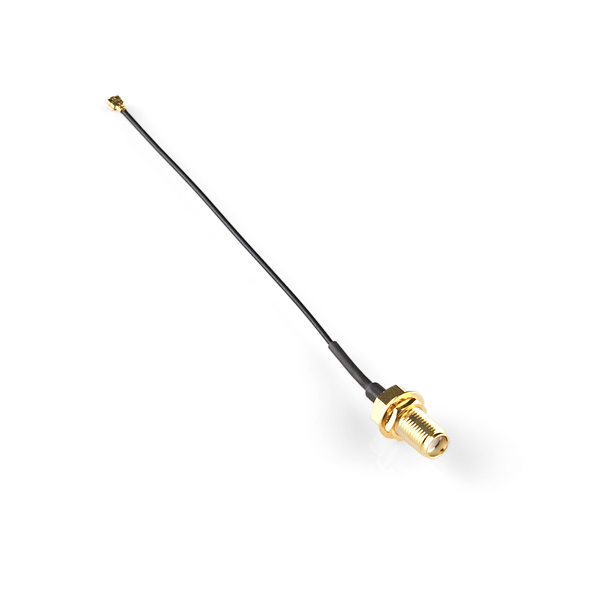
- 2x Interface Cable SMA to U.FL [WRL-09145]
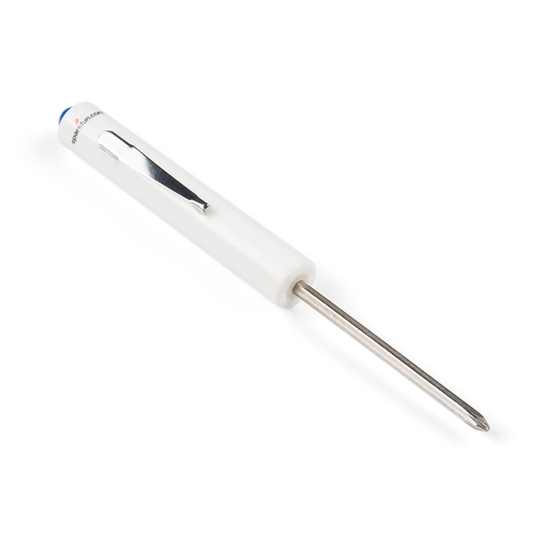
- 1x SparkFun Mini Screwdriver [TOL-09146]
* Note
If you use your own SIM card, please check that your chosen service provider offers LTE-M coverage for your area before purchasing.

Note
The SMA connections on the antennas are standard polarity. Antennas with reverse-polarity connectors are not suitable when connecting to the LTE GNSS Function Board and u.FL to SMA cables.
Suggested Reading
If you aren't familiar with the MicroMod Ecosystem, we recommend reading here for an overview.
If you aren’t familiar with the following concepts, we also recommend checking out a few of these tutorials before continuing.
Hardware Overview
We've broken out the SARA-R5 module (specifically the SARA-R510M8S-01B) to a MicroMod Function Board. Due to the design of the Function Board, we've rotated the board 180° relative to the label in the image shown below. In this section, we will highlight relevant components on the board. For more information about the u-blox SARA-R510M8S module, make sure to check the Resources tab.
 |
Power
The Function Board receives power typically from MicroMod Main Board's M.2 socket. Depending on your application, power can be provided via the Main Board's USB or a single cell LiPo Battery. If the Function Board's USB is also connected, a Schottky protection diode (the little rectangular black IC by the USB C connector) is included to prevent conflicting voltages. A resettable fuse is also included next to the USB connector as well. Power for the system is regulated down for the function board from the 3.3V AP7361C voltage regulator (square IC by the bottom left of the board). A dedicated 3.3V AP2112K voltage regulator (5-pin black IC) is also provided when using an active GNSS antenna. Additionally, the board includes an IC for voltage level translation (16 pin black IC on the bottom right of the board) for certain pins on the SARA-R510M8S.
 |
USB Type C Connector
Users can connect the module to a USB port. This can power the module as well. A Schottky protection diode is included to prevent conflicting voltages when the Main Board is connected to a power source. A resettable fuse is also provided. Compared to other u-blox modules, you will this is for the diagnostic interface and not to for flashing new firmware.
 |
Note
Please consult the SARA R5 Integration Manual for more details on using the diagnostic interface. You cannot (currently) upgrade the SARA via the diagnostic interface. Using the diagnostic interface is beyond the scope of this tutorial.
u.FL Connectors for LTE and GNSS
The MicroMod Main Board was intended to be included in an enclosure. Thus, the function board includes two u.FL connectors for the LTE and GNSS antennas. You will need a u.FL to SMA adapter for each antenna.
|
Nano SIM Socket
To connect to an LTE network, you will need a nano SIM card.
 |
On Button
The "ON" button to configure the SARA-R5 power settings. There are three modes: power on, power saving mode (PSM), or power OFF. Press and hold the button down to enter each mode for about 3 seconds. When fully powered, the LED will be bright red. In power saving mode, the LED will dim. When powered off, the LED will turn off.
 |
LEDs
The board includes four status LEDs:
- 3.3V — When lit, this indicates 3.3V power is available.
- Ring — When lit, this indicates when there is an event.
- NI — The LTE Network Indicator LED shows the cellular network status when the SARA-R5's GPIO1 is configured to act as a network status indicator output. The NI LED alternates from full Off (No service), full On (Data Transmission) as well as various pulse lengths to show different network statuses. Refer to section 17.1.3 of the AT Command Manual for the AT commands and description of this LED and the GPIO1/NI pin's behavior for different network states.
- LTE ON — The LTE ON LED indicates when the SARA-R5 module is powered on. When the LED is dim, this indicates that the SARA-R5 is in power saving mode. When the LED is off, the modules is powered off.
 |
Jumpers
Note
Never worked with solder jumpers and PCB traces before or need a quick refresher? Check out our How to Work with Solder Jumpers and PCB Traces tutorial for detailed instructions and tips.
The back of the board includes various jumpers:
- USB_SHLD — By default, this jumper is closed and connects the USB Type C connector's shield pin to GND. Cut this to isolate the USB Type C connector's shield pin.
- 3V3_LED — By default, this jumper is closed and connects to the output of the 3.3V voltage regulator. This is to indicate when 3.3V power is available for the SARA-R5 module. Cut this jumper to disable the 3.3V power LED and reduce the total current draw of the function board.
- ANT_REG_EN — By default, this jumper is closed and connects to the 3.3V AP2112K voltage regulator enable pin to the function board's general purpose I/O pin
F7. The voltage regulator is controlled through software to provide power to an active GNSS antenna. - LTE_PWR_ON — By default, this jumper is closed and connects the LTE power on pin to the function board's general purpose I/O pin
F5. The LTE_PWR_ON pin is active low. This pin can be controlled through software or manually with the button. - LTE_ON_LED — By default, this jumper is closed and connects to the LTE ON LED. Cut this to disable LED and reduce the total current draw of the function board.
- LTE_ON — By default, this jumper is closed and connects to the LTE ON pin to the function board's general purpose I/O pin
F1. Cut this to disable LED and reduce the total current draw of the function board. - LTE_RST — By default, this jumper is closed and connects the LTE reset pin to the function board's general purpose I/O pin
F2. The LTE_RST pin is active low. This pin is controlled through software and will reset the SARA-R5 module. - NI_LED — By default, this jumper is closed and connects to the LTE network indicator pin to an LED. Cut this to disable LED and reduce the total current draw of the function board.
- LTE_NI — By default, this jumper is closed and connects the LTE network indicator pin to the function board's general purpose I/O pin
F0. The LTE_NI pin is active low. - LTE_RI_LED — By default, this jumper is closed and connects the UART Ring Indicator to an LED. Cut this jumper to disable the 3.3V power LED and reduce the total current draw of the function board.
- I2C — By default, this three way jumper connects the 2.2kΩ pull-up resistors to the I2C data lines. Most of the time you can leave these alone unless your project requires you to disconnect the pull-up resistors.
- WP — By default, this jumper is open. Adding solder to the jumper pad will disable write protect for the EEPROM.
 |
EEPROM
The board includes an I2C EEPROM. Unfortunately, this is not available for the user and was meant to hold board specific information.
 |
Hardware Pinout
The LTE GNSS Function Board breaks out the SARA-R510M8S pins out to the edge of the board when connecting to a M.2 connector.
 |
Board Dimensions
The board uses the standard MicroMod Function Board size which measures about 37.49mm x 61.00mm (1.48" x 2.40").
 |
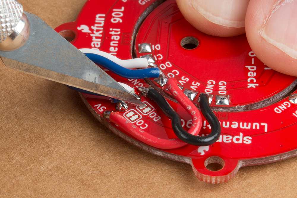
Hardware Assembly
Software Setup
AT Command Set
For users who want to go right into directly manipulating the SARA-R5 using the AT Command Set, review the AT Command Manual from u-blox:
Read on to the next sections if you prefer to use the MicroMod LTE GNSS Function Board with the SparkFun u-blox SARA-R5 Arduino Library.
Installing the Arduino Library
Note
Arduino IDE
This example assumes you are using the latest version of the Arduino IDE on your desktop. If this is your first time using Arduino IDE and an library, please review the following tutorials.
Board Definitions
For the scope of this tutorial, we will be using the MicroMod ESP32 Processor Board. If you have not installed a board definition before, please review the following tutorial as well.
USB-to-Serial Drivers
The MicroMod ESP32 Processor Board also uses the CP2104 USB-to-Serial converter (other compatible Processor Boards may require a different driver). Users will need to install the SiLabs CP2104 Driver, which can be found here: USB to UART Bridge VCP Driver. Make sure to manually install the driver for the CP2104 with the following instructions. The driver that Windows auto-installs will not work with the auto-reset circuit on the board and cause serial uploads to fail.
If applicable, make sure you are using the proper driver files for your CPU architecture. This is usually indicated by a folder or file name with "x86" for 32-bit processors or "x64" for 64-bit processors.
The SparkFun u-blox SARA-R5 Arduino Library provides a quick way to interact with the interfaces on the MicroMod LTE GNSS Function Board. Install the library through the Arduino Library Manager tool by searching for "SparkFun u-blox SARA-R5". Users who prefer to manually install the library can get it from the GitHub Repository or download the .ZIP by clicking the button below:
The library primarily works by associating a selection of AT Commands from the Command Set Manual with standard Arduino functions to run automatically in a sketch. View the full list of AT Commands included in this library (along with all other available functions) in the header file. The list of included AT Commands starts on line 93.
Note
When using the MicroMod ESP32 Processor Board with the SparkFun_u-blox_SARA-R5_Arduino_Library make sure to include the following line of code in the setup() function to enable the voltage regulator:
pinMode(PWM1, INPUT_PULLUP); // EN on F0 when using the ESP32 Processor BoardArduino Examples
The SparkFun u-blox SARA-R5 Arduino Library includes several examples to cover how to configure and use different features of the SARA-R5 module.
Make sure to go through the following examples to get the SARA-R5 registered and configured properly on your mobile network:
- Example 3 - Network Info
- Example 4 - Register Operator
- Example 7 - Configure Packet Switched Data
Example 1 - GNSS GPRMC
The first example enables the GNSS receiver and reads the GPRMC message for position, speed and time data. Open the example by navigating to File > Examples > SparkFun u-blox SARA-R5 Arduino Library > SARA-R5_Example1_GNSS_GPRMC.
Select your board in the Tools menu (in our case SparkFun ESP32 MicroMod) and the correct Port it enumerated on and click "Upload". After uploading the code, open the Serial Monitor or terminal emulator of your choice with the baud rate set to 115200. The code waits for a keyboard input from the user before progressing and running the setup and loop. After user input, the code prints out GPS data every second when there is a GPS lock.
 |
Note
Heads up! Make sure your GNSS antenna has a clear view of the open sky. Placing the antenna outdoors away from large objects (buildings, large trees, etc.) is best but if necessary you can usually place the antenna in a window that has a view of the sky to get a lock.
Code to Note
This function organizes the GPS data to print out neatly whenever the data returns as valid:
void printGPS(void)
{
  Serial.println();
  Serial.println("UTC: " + String(gps.utc));
  Serial.print("Time: ");
  if (clk.time.hour < 10) Serial.print('0'); // Print leading 0
  Serial.print(String(clk.time.hour) + ":");
  if (clk.time.minute < 10) Serial.print('0'); // Print leading 0
  Serial.print(String(clk.time.minute) + ":");
  if (clk.time.second < 10) Serial.print('0'); // Print leading 0
  Serial.print(String(clk.time.second) + ".");
  if (clk.time.ms < 10) Serial.print('0'); // Print leading 0
  Serial.println(String(clk.time.ms));
  Serial.println("Latitude: " + String(gps.lat, 7));
  Serial.println("Longitude: " + String(gps.lon, 7));
  Serial.println("Speed: " + String(spd.speed, 4) + " @ " + String(spd.cog, 4));
  Serial.println("Date (MM/DD/YY): " + String(clk.date.month) + "/" +
    String(clk.date.day) + "/" + String(clk.date.year));
  Serial.println("Magnetic variation: " + String(spd.magVar));
  Serial.println("Status: " + String(gps.status));
  Serial.println("Mode: " + String(gps.mode));
  Serial.println();
}
Example 2 - Identification
The second example prompts the LTE module to read the SARA-R5's identification information:
- Manufacturer ID
- Model
- Firmware Version
- Serial Number
- IMEI ID
- IMSI ID
- SIM CCID
- Subscriber Number (from the SIM)
- Capabilities
- SIM state
This example primarily functions as a check to make sure the SARA-R5 is working properly and the SIM card is detected then polls the SIM status in the main loop. Upload the code and open a terminal window with the baud set to 115200. The code initializes the SARA-R5 and after a user input, initializes the SARA-R5 and prints out the ID information and SIM state.
Open the example by navigating to File > Examples > SparkFun u-blox SARA-R5 Arduino Library > SARA-R5_Example2_Identification.
If you have not already, select your board in the Tools menu (in our case SparkFun ESP32 MicroMod) and the correct Port it enumerated on and click "Upload". After uploading the code, open the Serial Monitor with the baud rate set to 115200. Again, the code waits for a keyboard input from the user before progressing and running the setup and loop.
Make sure to wait for the blue NI LED to light up first before sending a character through the terminal window. Once there is a network in range, send a character to run the example. You will see the SARA-R5's identification information printed out.
 |
Example 3 - Network Info
This example verifies the SARA-R5 is receiving an LTE signal on a selected network and prints out the network information and IDs. The code creates the SARA-R5 object and assigns a network operator value. Depending on the network for your SIM card uses, adjust this line:
const mobile_network_operator_t MOBILE_NETWORK_OPERATOR = MNO_GLOBAL;
Open the example by navigating to File > Examples > SparkFun u-blox SARA-R5 Arduino Library > SARA-R5_Example3_NetworkInfo.
If you have not already, select your board in the Tools menu (in our case SparkFun ESP32 MicroMod) and the correct Port it enumerated on and click "Upload". After uploading the code, open the Serial Monitor with the baud rate set to 115200. Wait for the blue NI LED to light up and then send a keyboard input.
After initializing everything needed, the code attempts to set the Network Profile to the Mobile Network Operator entered. If successful, the code prints out the RSSI (Received Signal Strength), Network Registration Status and Context IDs, Access Point Names and IP Addresses.
 |
Depending on the output in the Serial Monitor, you may need to scroll down to view the Context ID, APN, and IP Address.
Example 4 - Register Operator
Example 4 checks to see if the SARA-R5 is connected to a network and lets you register on a different network if available and if the SIM supports this. This example can also be used to list all the LTE operators the SARA-R5 can detect.
Note
You can only connect to networks supported by your SIM card. Refer to your SIM card manufacturer's documentation for supported networks.
Open the example by navigating to File > Examples > SparkFun u-blox SARA-R5 Arduino Library > SARA-R5_Example4_RegisterOperator.
If you have not already, select your board in the Tools menu (in our case SparkFun ESP32 MicroMod) and the correct Port it enumerated on and click "Upload". After uploading the code, open the Serial Monitor with the baud rate set to 115200. Wait for the blue NI LED to light up and then send a keyboard input.
 |
Example 7 - Configure Packed Switched Data
Example 7 configures the "Context Identifier" for the mobile data connection. Make sure to go through this example to properly set up your SARA-R5 Context ID.
Open the example by navigating to File > Examples > SparkFun u-blox SARA-R5 Arduino Library > SARA-R5_Example7_ConfigurePacketSwitchedData.
If you have not already, select your board in the Tools menu (in our case SparkFun ESP32 MicroMod) and the correct Port it enumerated on and click "Upload". After uploading the code, open the Serial Monitor with the baud rate set to 115200. Wait for the blue NI LED to light up and then send a keyboard input. Then follow the prompts to select the appropriate Context ID. You may see a few Context IDs so make sure to select one that looks correct (i.e. not a blank IP):
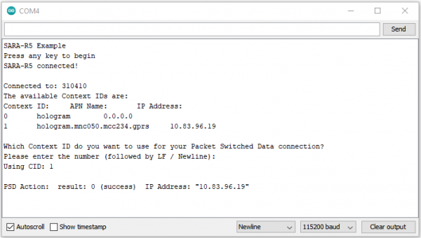 |
The code provides a warning that “deactivate profile failed”. We see this because the SARA needs to disconnect from a profile before it can connect to a new one, and in this case this failed because there was no profile active. Don't worry about this warning, it is just there for information. The example shows that our connection was successful by displaying the Internet Protocol (IP) address the SARA has been allocated by the service operator.
Example 5 - Receive SMS
The fifth example demonstrates how to read and print any SMS text messages the SARA-R5 receives. The code checks whether the module is connected to an operator and will freeze if unsuccessful. If the code freezes here, wait and retry as it may be a connection issue with your network. Otherwise, return to Examples 3 and 4 to set up the Network Operator.
Open the example by navigating to File > Examples > SparkFun u-blox SARA-R5 Arduino Library > SARA-R5_Example5_ReceiveSMS.
The main loop accesses the message storage memory used for reading and deleting messages for data and prints the used and total number of memory locations in the message storage.
The code waits for any new messages to arrive and prints the Message Index (location), Status, Originator, Date and Time and then the message contents.
New messages are automatically marked as read once the code prints them. To force the code to print all the messages stored in the message memory, comment out this line:
if (unread == "REC UNREAD")
If you have not already, select your board in the Tools menu (in our case SparkFun ESP32 MicroMod) and the correct Port it enumerated on and click "Upload". After uploading the code, open the Serial Monitor with the baud rate set to 115200. Wait for the blue NI LED to light up and then send a keyboard input.
Assuming that you registered and activated your Hologram SIM card, log into your Hologram account. Head to the Devices and select the SIM card. Then select the Messaging tab and write message. Hit Send SMS message button.
 |
If all goes well, you will notice that the message was sent successfully!
 |
Head back to you Arduino Serial Monitor to view the message. You should see the message that was originally written in the Serial Monitor. Sweet!
 |
Before moving onto the next example, make sure to keep track of the "Originator". This is the number that is associated with the SIM card and your Hologram account.
Example 6 - Send SMS
Note
Depending on your network, you may have issues sending a SMS message to a smartphone. Even if you have the correct phone number entered and you receive a response that the message was sent successfully to your network, the service carrier may block the message from being sent to your smartphone. For more information, check out the article about Troubleshooting Undelivered SMS Messages Sent To or From a Hologram Device.
The sixth example sends SMS messages to another phone or LTE module from the SparkFun LTE GNSS Function Board - SARA-R5. The code prompts the user for the destination number and message contents.
Open the example by navigating to File > Examples > SparkFun u-blox SARA-R5 Arduino Library > SARA-R5_Example6_SendSMS.
If you have not already, select your board in the Tools menu (in our case SparkFun ESP32 MicroMod) and the correct Port it enumerated on and click "Upload". After uploading the code, open the Serial Monitor with the baud rate set to 115200. Wait for the blue NI LED to light up and then send a keyboard input. Enter the message that you want to send and the destination number.
 |
Assuming that you are using a Hologram SIM card, head back to your Hologram account. Expand the window where it says "All activity". You should see the original message that was sent from the SARA-R5!
Troubleshooting
This section outlines a few troubleshooting tips and common snags when using the SparkFun LTE GNSS FUnction Board - SARA-R5.
LTE Network Availability
The SARA-R5 supports LTE-M and NB-IoT data communication for multi-regional use. Please check the LTE signal availability for your area before purchasing a SARA-R5 product and selecting an LTE service provider / operator.
Data Connectivity
When working through the data connectivity examples, it is important that you run examples 13, 14 and 17 in order, before moving on to example 18 or 19. Each example builds on the last and together they configure the SARA’s data connection correctly.
Arduino Debug Messages
If you run into any trouble using one of the Arduino examples, uncomment this line:
assetTracker.enableDebugging(SERIAL_PORT);
This enables serial debugging to print out the full debug report from AT commands sent via functions in the library. Read through the data and search for matching error codes in Appendix A of the AT Command Reference manual to decipher the code.
Resources
Now that you've successfully got your SparkFun MicroMod LED GNSS Function Board - SARA-R5 up and running, it's time to incorporate it into your own project! For more information, check out the resources below:
- LTE GNSS Function Board - SARA-R5 Documentation
- u-blox SARA-R5 LTE-M / NB-IoT Module Documentation
- MicroMod