Arduino Examples
Attention
All of the examples require the user to enter a key into the serial monitor before the example starts, which triggers the IMU calibration.
Attention
The IMU on the Optical Tracking Odometry Sensor includes a gyroscope and accelerometer, which could have an offset. The OTOS performs a quick calibration when it powers up, but it is recommended to perform a more thorough calibration at the start of all your programs.
Example 1: Basic Readings
This first example just does some basic measurements to make sure everything is hooked up correctly. To find Example 1, go to File > Examples > SparkFun Qwiic OTOS > Example1_BasicReadings:

Finding Example 1
Alternatively, you can expand the link below and copy and paste the code into a shiny new Arduino sketch:
Example 1 Arduino Code
/*
    SPDX-License-Identifier: MIT

    Copyright (c) 2024 SparkFun Electronics
*/

/*******************************************************************************
    Example 1 - Basic Readings

    This example demonstrates how to read the position and heading from the
    SparkFun Qwiic Optical Tracking Odometry Sensor (OTOS).

    This example should be used to verify that the OTOS is connected and
    functioning correctly. It will just print the position and heading tracked
    by the OTOS to the serial monitor. It is recommended that you check out the
    other examples before using the OTOS in your own project.
*******************************************************************************/

#include "SparkFun_Qwiic_OTOS_Arduino_Library.h"
#include "Wire.h"

// Create an Optical Tracking Odometry Sensor object
QwiicOTOS myOtos;

void setup()
{
    // Start serial
    Serial.begin(115200);
    Serial.println("Qwiic OTOS Example 1 - Basic Readings");

    Wire.begin();

    // Attempt to begin the sensor
    while (myOtos.begin() == false)
    {
        Serial.println("OTOS not connected, check your wiring and I2C address!");
        delay(1000);
    }

    Serial.println("OTOS connected!");

    Serial.println("Ensure the OTOS is flat and stationary, then enter any key to calibrate the IMU");

    // Clear the serial buffer
    while (Serial.available())
        Serial.read();
    // Wait for user input
    while (!Serial.available())
        ;

    Serial.println("Calibrating IMU...");

    // Calibrate the IMU, which removes the accelerometer and gyroscope offsets
    myOtos.calibrateImu();

    // Reset the tracking algorithm - this resets the position to the origin,
    // but can also be used to recover from some rare tracking errors
    myOtos.resetTracking();
}

void loop()
{
    // Get the latest position, which includes the x and y coordinates, plus the
    // heading angle
    sfe_otos_pose2d_t myPosition;
    myOtos.getPosition(myPosition);

    // Print measurement
    Serial.println();
    Serial.println("Position:");
    Serial.print("X (Inches): ");
    Serial.println(myPosition.x);
    Serial.print("Y (Inches): ");
    Serial.println(myPosition.y);
    Serial.print("Heading (Degrees): ");
    Serial.println(myPosition.h);

    // Wait a bit so we don't spam the serial port
    delay(500);

    // Alternatively, you can comment out the print and delay code above, and
    // instead use the following code to rapidly refresh the data
    // Serial.print(myPosition.x);
    // Serial.print("\t");
    // Serial.print(myPosition.y);
    // Serial.print("\t");
    // Serial.println(myPosition.h);
    // delay(10);
}
Make sure you've selected the correct board and port in the Tools menu and then hit the upload button. Once the code has finished uploading, go ahead and open a Serial Monitor. You should see something similar to the following.

Example 1 Output
Move the sensor around to see how the coordinates change!
Example 2: SetUnits
This example sets the desired units for linear and angular measurements. Can be either meters or inches for linear, and radians or degrees for angular. If not set, the default is inches and degrees. Note that this setting is not stored in the sensor, it's part of the library, so you need to set at the start of all your programs.
To find Example 2, go to File > Examples > SparkFun Qwiic OTOS > Example2_SetUnits:

Finding Example 2
Alternatively, you can expand the link below and copy and paste the code into a shiny new Arduino sketch:
Example 2 Arduino Code
/*
    SPDX-License-Identifier: MIT

    Copyright (c) 2024 SparkFun Electronics
*/

/*******************************************************************************
    Example 2 - Set Units

    This example demonstrates how to change the units of the SparkFun Qwiic
    Optical Tracking Odometry Sensor (OTOS).

    The OTOS library defaults to inches and degrees, but you can change the
    units to suit the needs of your project.
*******************************************************************************/

#include "SparkFun_Qwiic_OTOS_Arduino_Library.h"
#include "Wire.h"

// Create an Optical Tracking Odometry Sensor object
QwiicOTOS myOtos;

void setup()
{
    // Start serial
    Serial.begin(115200);
    Serial.println("Qwiic OTOS Example 2 - Set Units");

    Wire.begin();

    // Attempt to begin the sensor
    while (myOtos.begin() == false)
    {
        Serial.println("OTOS not connected, check your wiring and I2C address!");
        delay(1000);
    }

    Serial.println("OTOS connected!");

    Serial.println("Ensure the OTOS is flat and stationary, then enter any key to calibrate the IMU");

    // Clear the serial buffer
    while (Serial.available())
        Serial.read();
    // Wait for user input
    while (!Serial.available())
        ;

    Serial.println("Calibrating IMU...");

    // Calibrate the IMU, which removes the accelerometer and gyroscope offsets
    myOtos.calibrateImu();

    // Set the desired units for linear and angular measurements. Can be either
    // meters or inches for linear, and radians or degrees for angular. If not
    // set, the default is inches and degrees. Note that this setting is not
    // stored in the sensor, it's part of the library, so you need to set at the
    // start of all your programs.
    myOtos.setLinearUnit(kSfeOtosLinearUnitMeters);
    // myOtos.setLinearUnit(kSfeOtosLinearUnitInches);
    myOtos.setAngularUnit(kSfeOtosAngularUnitRadians);
    // myOtos.setAngularUnit(kSfeOtosAngularUnitDegrees);

    // Reset the tracking algorithm - this resets the position to the origin,
    // but can also be used to recover from some rare tracking errors
    myOtos.resetTracking();
}

void loop()
{
    // Get the latest position, which includes the x and y coordinates, plus the
    // heading angle
    sfe_otos_pose2d_t myPosition;
    myOtos.getPosition(myPosition);

    // Print measurement
    Serial.println();
    Serial.println("Position:");
    Serial.print("X (Meters): ");
    Serial.println(myPosition.x, 4);
    Serial.print("Y (Meters): ");
    Serial.println(myPosition.y, 4);
    Serial.print("Heading (Radians): ");
    Serial.println(myPosition.h, 4);

    // Wait a bit so we don't spam the serial port
    delay(500);
}
Notice the following code snippet - this is the section of code that allows you to choose your units:

Example 2 Code To Change Units
Make sure you've selected the correct board and port in the Tools menu and then hit the upload button. Once the code has finished uploading, go ahead and open a Serial Monitor. You should see something similar to the following.

Example 2 Output
Example 3: Calibration
Warning
As of firmware version 1.0, these calibration values will be lost after a power cycle, so you will need to set them each time you power up the sensor.
The data from the OTOS will likely have minor scaling errors that can be calibrated out. This is especially important for the angular scalar, because an incorrect angle measurement causes the linear measurements to be rotated by the wrong angle in the firmware, which can lead to very inaccurate tracking.
To find Example 3, go to File > Examples > SparkFun Qwiic OTOS > Example3_Calibration:

Finding Example 3
Alternatively, you can expand the link below and copy and paste the code into a shiny new Arduino sketch:
Example 3 Arduino Code
/*
    SPDX-License-Identifier: MIT

    Copyright (c) 2024 SparkFun Electronics
*/

/*******************************************************************************
    Example 3 - Calibration

    This example demonstrates how to calibrate the SparkFun Qwiic Optical
    Tracking Odometry Sensor (OTOS).

    This example should be used to calibrate the linear and angular scalars of
    the OTOS to get the most accurate tracking performance. The linear scalar
    can be used to compensate for scaling issues with the x and y measurements,
    while the angular scalar can be used to compensate for scaling issues with
    the heading measurement. Note that if the heading measurement is off, that
    can also cause the x and y measurements to be off, so it's recommended to
    calibrate the angular scalar first.
*******************************************************************************/

#include "SparkFun_Qwiic_OTOS_Arduino_Library.h"
#include "Wire.h"

// Create an Optical Tracking Odometry Sensor object
QwiicOTOS myOtos;

void setup()
{
    // Start serial
    Serial.begin(115200);
    Serial.println("Qwiic OTOS Example 3 - Calibration");

    Wire.begin();

    // Attempt to begin the sensor
    while (myOtos.begin() == false)
    {
        Serial.println("OTOS not connected, check your wiring and I2C address!");
        delay(1000);
    }

    Serial.println("OTOS connected!");

    Serial.println("Ensure the OTOS is flat and stationary, then enter any key to calibrate the IMU");

    // Clear the serial buffer
    while (Serial.available())
        Serial.read();
    // Wait for user input
    while (!Serial.available())
        ;

    Serial.println("Calibrating IMU...");

    // The IMU on the OTOS includes a gyroscope and accelerometer, which could
    // have an offset. Note that as of firmware version 1.0, the calibration
    // will be lost after a power cycle; the OTOS performs a quick calibration
    // when it powers up, but it is recommended to perform a more thorough
    // calibration at the start of all your programs. Note that the sensor must
    // be completely stationary and flat during calibration! When calling
    // calibrateImu(), you can specify the number of samples to take and whether
    // to wait until the calibration is complete. If no parameters are provided,
    // it will take 255 samples and wait until done; each sample takes about
    // 2.4ms, so about 612ms total
    myOtos.calibrateImu();

    // Alternatively, you can specify the number of samples and whether to wait
    // until it's done. If you don't want to wait, you can asynchronously check
    // how many samples remain with the code below. Once zero samples remain,
    // the calibration is done!
    // myOtos.calibrateImu(255, false);
    // bool done = false;
    // while(done == false)
    // {
    //     // Check how many samples remain
    //     uint8_t samplesRemaining;
    //     myOtos.getImuCalibrationProgress(samplesRemaining);

    //     // If 0 samples remain, the calibration is done
    //     if(samplesRemaining == 0)
    //         done = true;
    // }

    // Here we can set the linear and angular scalars, which can compensate for
    // scaling issues with the sensor measurements. Note that as of firmware
    // version 1.0, these values will be lost after a power cycle, so you will
    // need to set them each time you power up the sensor. They can be any value
    // from 0.872 to 1.127 in increments of 0.001 (0.1%). It is recommended to
    // first set both scalars to 1.0, then calibrate the angular scalar, then
    // the linear scalar. To calibrate the angular scalar, spin the robot by
    // multiple rotations (eg. 10) to get a precise error, then set the scalar
    // to the inverse of the error. Remember that the angle wraps from -180 to
    // 180 degrees, so for example, if after 10 rotations counterclockwise
    // (positive rotation), the sensor reports -15 degrees, the required scalar
    // would be 3600/3585 = 1.004. To calibrate the linear scalar, move the
    // robot a known distance and measure the error; do this multiple times at
    // multiple speeds to get an average, then set the linear scalar to the
    // inverse of the error. For example, if you move the robot 100 inches and
    // the sensor reports 103 inches, set the linear scalar to 100/103 = 0.971
    myOtos.setLinearScalar(1.0);
    myOtos.setAngularScalar(1.0);

    // Reset the tracking algorithm - this resets the position to the origin,
    // but can also be used to recover from some rare tracking errors
    myOtos.resetTracking();
}

void loop()
{
    // Get the latest position, which includes the x and y coordinates, plus the
    // heading angle
    sfe_otos_pose2d_t myPosition;
    myOtos.getPosition(myPosition);

    // Print measurement
    Serial.println();
    Serial.println("Position:");
    Serial.print("X (Inches): ");
    Serial.println(myPosition.x);
    Serial.print("Y (Inches): ");
    Serial.println(myPosition.y);
    Serial.print("Heading (Degrees): ");
    Serial.println(myPosition.h);

    // Wait a bit so we don't spam the serial port
    delay(500);

}
Make sure you've selected the correct board and port in the Tools menu and then hit the upload button. Once the code has finished uploading, go ahead and open a Serial Monitor.
Calibrating your bot requires you to move it around a bit. First, set both scalars to 1.0, then calibrate the angular scalar, then the linear scalar.
To calibrate the angular scalar, spin the robot by multiple rotations (eg. 10) to get a precise error, then set the scalar to the inverse of the error. Remember that the angle wraps from -180 to 180 degrees, so for example, if after 10 rotations counterclockwise(positive rotation), the sensor reports -15 degrees, the required scalar would be 3600/3585 = 1.004.

Rotating the Optical Tracking Odometry Sensor
To calibrate the linear scalar, move the robot a known distance and measure the error; do this multiple times at multiple speeds to get an average, then set the linear scalar to the inverse of the error. For example, if you move the robot 100 inches and the sensor reports 103 inches, set the linear scalar to 100/103 = 0.971.

Moving the Optical Tracking Odometry Sensor
Example 4: SetOffsetAndPosition
This example shows how to set the offset for the sensor relative to the center of the robot. The units default to inches and degrees, but if you want to use different units, make sure you specify them before setting the offset. Without setting the offset, the OTOS will report the coordinates of itself. If the offset is set, the OTOS will instead report the coordinates of the center of your robot.
Note that the OTOS typically starts tracking from the origin, but if your robot starts at some other location, or you have another source of location information from another sensor that's more accurate, you can send the current location to the OTOS and it will continue tracking from there.
Warning
As of firmware version 1.0, these values will be lost after a power cycle, so you will need to set them each time you power up the sensor.
To find Example 4, go to File > Examples > SparkFun Qwiic OTOS > Example4_SetOffsetAndPosition:

Finding Example 4
Alternatively, you can expand the link below and copy and paste the code into a shiny new Arduino sketch:
Example 4 Arduino Code
/*
    SPDX-License-Identifier: MIT

    Copyright (c) 2024 SparkFun Electronics
*/

/*******************************************************************************
    Example 4 - Set Offset and Position

    This example demonstrates how to set the offset and position of the SparkFun
    Qwiic Optical Tracking Odometry Sensor (OTOS).

    If your OTOS is mounted to a robot and is not centered, you can specify the
    offset for the sensor relative to the center of the robot; rather than
    returning the position of the sensor, the OTOS will calculate and return the
    position of the robot's center. If you know where your robot is located,
    such as the starting location or from another sensor, you can send that
    position to the OTOS and it will continue to track from there.
*******************************************************************************/

#include "SparkFun_Qwiic_OTOS_Arduino_Library.h"
#include "Wire.h"

// Create an Optical Tracking Odometry Sensor object
QwiicOTOS myOtos;

void setup()
{
    // Start serial
    Serial.begin(115200);
    Serial.println("Qwiic OTOS Example 4 - Set Offset and Position");

    Wire.begin();

    // Attempt to begin the sensor
    while (myOtos.begin() == false)
    {
        Serial.println("OTOS not connected, check your wiring and I2C address!");
        delay(1000);
    }

    Serial.println("OTOS connected!");

    Serial.println("Ensure the OTOS is flat and stationary, then enter any key to calibrate the IMU");

    // Clear the serial buffer
    while (Serial.available())
        Serial.read();
    // Wait for user input
    while (!Serial.available())
        ;

    Serial.println("Calibrating IMU...");

    // Calibrate the IMU, which removes the accelerometer and gyroscope offsets
    myOtos.calibrateImu();

    // Assuming you've mounted your sensor to a robot and it's not centered,
    // you can specify the offset for the sensor relative to the center of the
    // robot. The units default to inches and degrees, but if you want to use
    // different units, specify them before setting the offset! Note that as of
    // firmware version 1.0, these values will be lost after a power cycle, so
    // you will need to set them each time you power up the sensor. For example, if
    // the sensor is mounted 5 inches to the left (negative X) and 10 inches
    // forward (positive Y) of the center of the robot, and mounted 90 degrees
    // clockwise (negative rotation) from the robot's orientation, the offset
    // would be {-5, 10, -90}. These can be any value, even the angle can be
    // tweaked slightly to compensate for imperfect mounting (eg. 1.3 degrees).
    sfe_otos_pose2d_t offset = {-5, 10, -90};
    myOtos.setOffset(offset);

    // Reset the tracking algorithm - this resets the position to the origin,
    // but can also be used to recover from some rare tracking errors
    myOtos.resetTracking();

    // After resetting the tracking, the OTOS will report that the robot is at
    // the origin. If your robot does not start at the origin, or you have
    // another source of location information (eg. vision odometry), you can set
    // the OTOS location to match and it will continue to track from there.
    sfe_otos_pose2d_t currentPosition = {0, 0, 0};
    myOtos.setPosition(currentPosition);
}

void loop()
{
    // Get the latest position, which includes the x and y coordinates, plus the
    // heading angle
    sfe_otos_pose2d_t myPosition;
    myOtos.getPosition(myPosition);

    // Print measurement
    Serial.println();
    Serial.println("Position:");
    Serial.print("X (Inches): ");
    Serial.println(myPosition.x);
    Serial.print("Y (Inches): ");
    Serial.println(myPosition.y);
    Serial.print("Heading (Degrees): ");
    Serial.println(myPosition.h);

    // Wait a bit so we don't spam the serial port
    delay(500);

}
If the sensor is mounted 5 inches to the left (negative X) and 10 inches forward (positive Y) of the center of the robot, and mounted 90 degrees clockwise (negative rotation) from the robot's orientation, the offset would be {-5, 10, -90}. These can be any value, even the angle can be tweaked slightly to compensate for imperfect mounting (eg. 1.3 degrees).
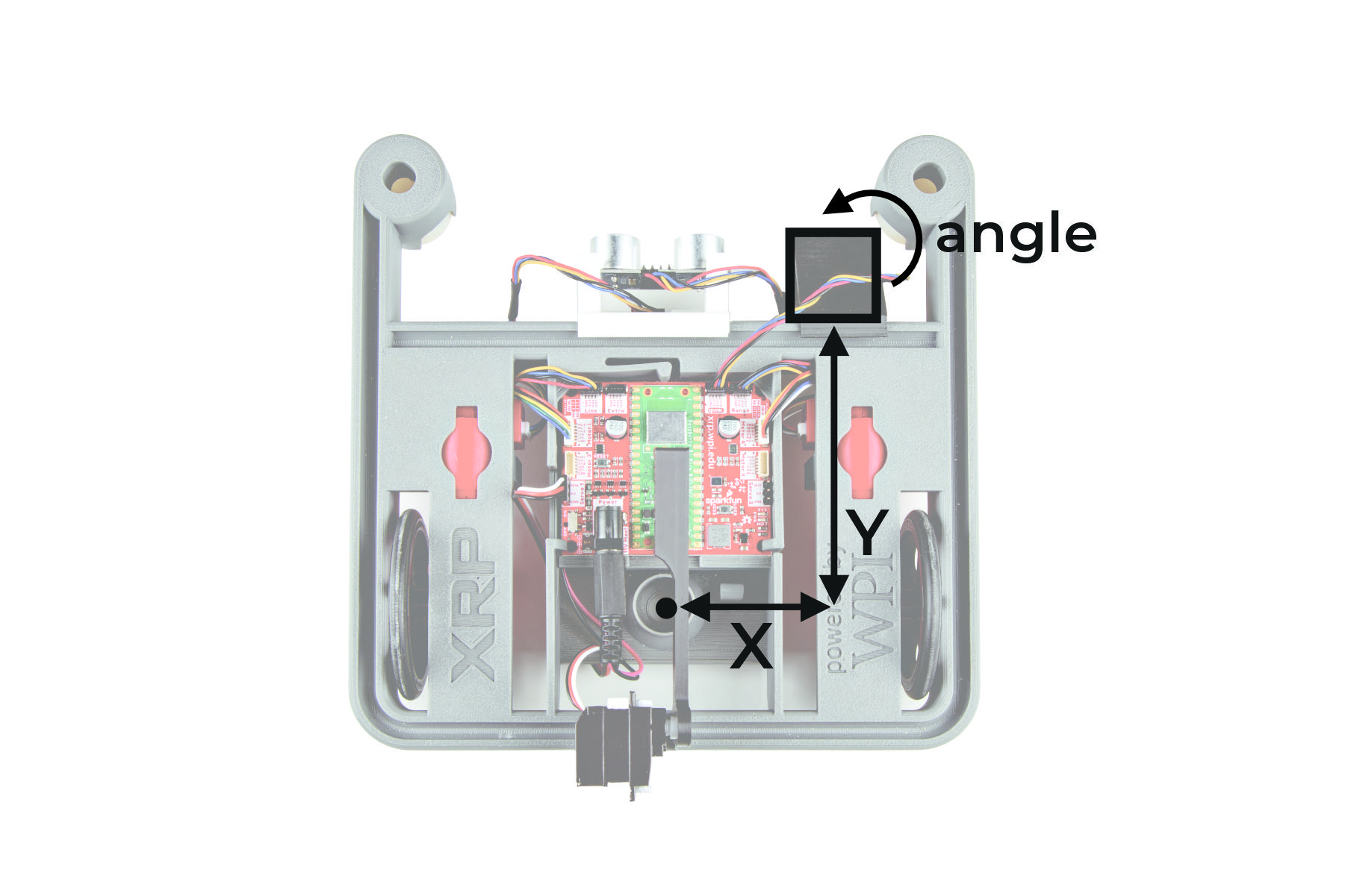
The X, Y, and Angular Offset of the Optical Tracking Sensor
These four examples cover the basics - there are more examples to explore in the library!