-
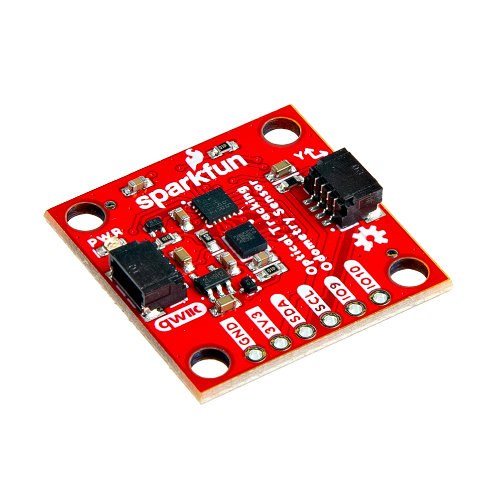
SparkFun Optical Tracking Odometry Sensor - PAA5160E1 (Qwiic)
SKU: SEN-24904
-
The SparkFun Qwiic Optical Tracking Odometry Sensor empowers you to elevate your robot's navigation capabilities with exceptional precision and streamlined integration. This compact, all-in-one sensor leverages the power of the PAA5160E1 chip from PixArt Imaging Inc., delivering accurate dual-axis motion data across various hard floor surfaces. But that's not all! This sensor boasts a powerful built-in 6-axis Inertial Measurement Unit (IMU) and an onboard microcontroller that performs real-time sensor fusion and tracking algorithms.
Purchase from SparkFun
Required Materials
To follow along with this tutorial, you will need the following materials. You may not need everything though depending on what you have. Add it to your cart, read through the guide, and adjust the cart as necessary.
SparkFun Optical Tracking Odometry Sensor - PAA5160E1 (Qwiic)SEN-24904 |
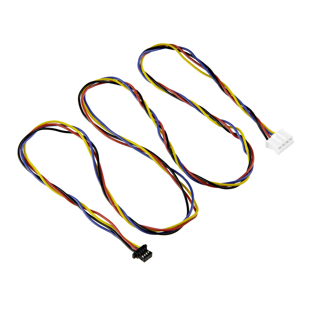 Flexible Qwiic to STEMMA Cable - 500mmCAB-25596 |
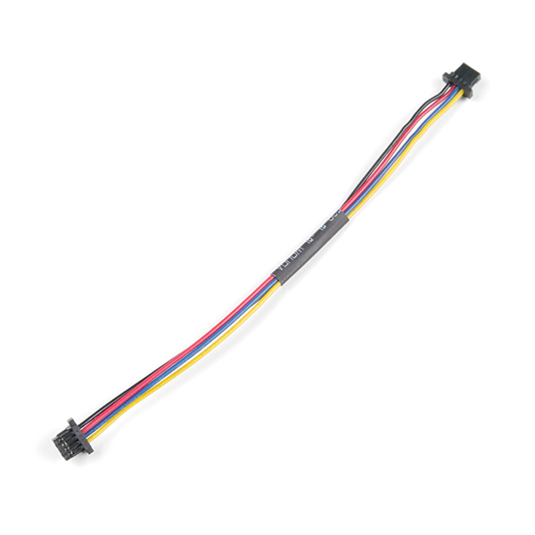
Qwiic Cable - 100mmcPRT-14427 |
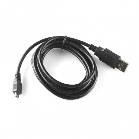
USB micro-B Cable - 6 FootCAB-10215 |
Experiential Robotics Platform (XRP) Kit - BetaKIT-22230 |
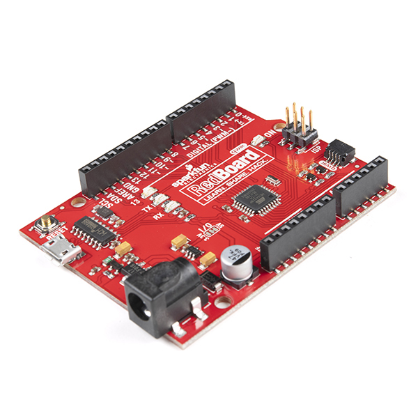
SparkFun RedBoard QwiicDEV-15123 |
Suggested Reading
Below are a few tutorials that may help users familiarize themselves with various aspects of the board.
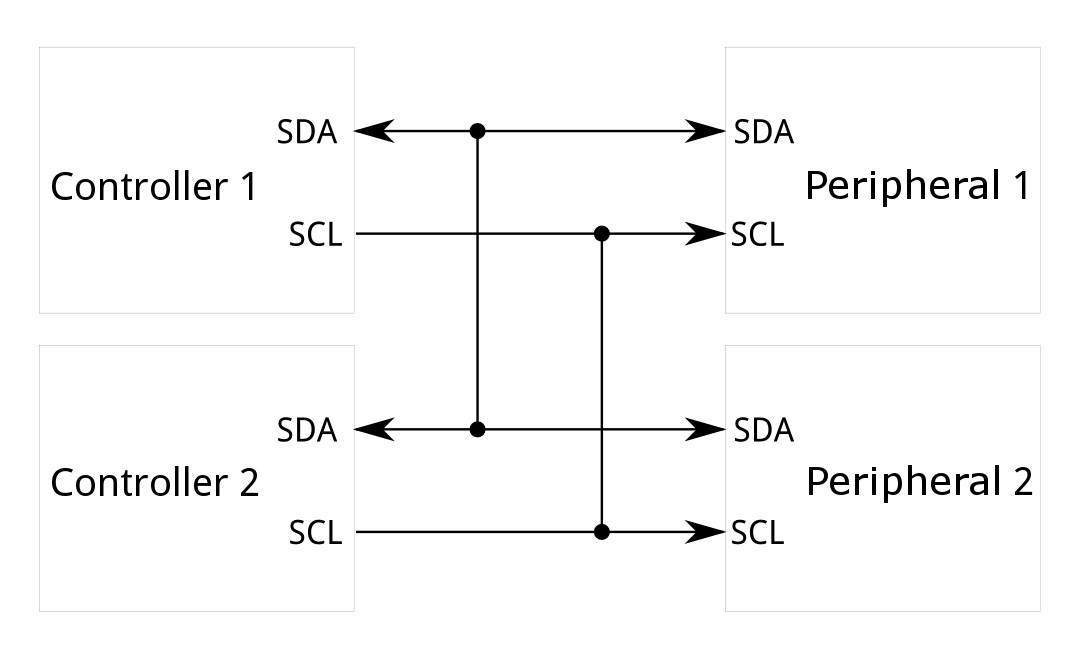
The SparkFun Optical Tracking Odometry Sensor - PAA5160E1 (Qwiic) takes advantage of the Qwiic connect system. We recommend familiarizing yourself with the Logic Levels and I2C tutorials. Click on the banner above to learn more about Qwiic products.
Hardware Overview
Optical Tracking Sensor - PAA5160
The PAA5160E1-Q from PixArt Imaging has a tracking speed of 2.5m/s and a typical tracking error rate of 3~5% within a working range of 10mm to 27mm. With an 850nm Class 1 laser, a resolution of 20,000 DPI, and a frame rate of 20,000 fps, it is ideal for surfaces like concrete, epoxy, laminated wood, or glossy/semi-glossy flooring. That said, dark or diffuse surfaces are more challenging, so these specs may vary based on the surfaces that are being used. More information can be found in the datasheet.
![]()
Optical Tracking Sensor - PAA5160
Warning
The laser on this module is a Class 1, 850nm laser. Please use appropriate caution.

6-DoF IMU - LSM6DSO
The LSM6DSO from STMicroelectronics has a 3-axis digital accelerometer and 3-axis digital gyroscope featuring a full-scale acceleration range of ±2/±4/±8/±16 g and an angular rate range of ±125/±250/±500/±1000/±2000 dps. For more information, refer to the datasheet.
![]()
LSM6DSO 6-DOF IMU Accelerometer
Microcontroller - STM32C0
The STM32C011F4U6 microcontroller has a high-performance Arm® Cortex®-M0+ 32-bit RISC core operating at up to 48 MHz frequency. It incorporates a memory protection unit (MPU), high-speed embedded memory (6 Kbytes of SRAM and up to 32 Kbytes of flash program memory with read and write protection), DMA, an extensive range of system functions, enhanced I/Os, and peripherals. The device offers standard communication interfaces (one I2C, one SPI / one I2S, and two USARTs), one 12-bit ADC (2.5 MSps) with up to 15 channels, a low-power RTC, an advanced control PWM timer, four general-purpose 16-bit timers, two watchdog timers, and a SysTick timer. For more information, refer to the datasheet.
![]()
STM32 Processor
Power
The LED indicator lights when power is provided to the board.
![]()
Power LED
Qwiic Connectors
The Qwiic Connectors on the SparkFun Optical Tracking Odometry Sensor - PAA5160E1 (Qwiic) provide power and I2C connectivity simultaneously. The I2C address is 0x17.
![]()
Qwiic Connectors
GPIO
The PTH pins on the side of the board allow you to provide power, access the I2C Data and Clock lines, and there are two pins available for UART/generic programming purposes. In normal operation, IO9 acts as a "data ready" interrupt; this pin could be used to synchronize measurements if needed. Outside of normal operation, IO9 and IO10 provide a UART interface that can be used for firmware updates, see instructions here.
![]()
GPIO
Debugging Test Points
We've broken out test points for serial wire debugging if you wish to access flash memory or directly program the board. They are located here:
![]()
Debugging Test Points
Jumpers
Never modified a jumper before?
Check out our Jumper Pads and PCB Traces tutorial for a quick introduction!

Power Jumper
If you are concerned about power consumption, need to run dark, or just really don't like LEDs, cut the jumper highlighted below to disconnect power from the LED on the front of the board.
![]()
Power Jumper
I2C Jumper
If you choose to use one or more Qwiic breakouts in your project, it is important to note that this board comes equipped with pull-up resistors on the clock and data pins. If you are daisy-chaining multiple Qwiic devices, you will want to cut this jumper; if multiple sensors are connected to the bus with the pull-up resistors enabled, the parallel equivalent resistance will create too strong of a pull-up for the bus to operate correctly. As a general rule of thumb, disable all but one pair of pull-up resistors if multiple devices are connected to the bus. To disable the pull up resistors, use an X-acto knife to cut the joints between the jumper pads highlighted below.
![]()
I2C Jumper
Board Dimensions
The board dimensions are illustrated in the drawing below; the listed measurements are in inches.
![]()
SparkFun Optical Tracking Odometry Sensor Board Dimensions
Need more measurements?
For more information about the board's dimensions, users can download the Eagle files. These files can be opened in Eagle and additional measurements can be made with the dimensions tool.
Eagle - Free Download!
Eagle is a CAD program for electronics that is free to use for hobbyists and students. However, it does require an account registration to utilize the software.
 Dimensions Tool
This video from Autodesk demonstrates how to utilize the dimensions tool in Eagle, to include additional measurements:
Hardware Assembly
The SparkFun Optical Tracking Odometry Sensor needs to be rigidly mounted to a robot chassis and oriented flat to the floor in order to get accurate data. If you don't already have a mount, there are a few 3D printing models you can use. That said, you may need to design your own mount for this board, depending on your use case.
The height that the sensor needs to be mounted will be dependent on the surface being read. If you have a shiny or glossy surface, you should be able to mount the sensor anywhere in the range of 10mm to 27mm, measured from the front face of the optical sensor. If you have a darker or more diffuse surface, you may need to mount the sensor at the low-end of that range. You'll need to test to determine what height works for your surface.
You can access the XRP mount on Printables:
Warning
Accurate readings require that the sensor is mounted correctly; attempting to move the sensor by hand may work, but tracking accuracy will suffer.
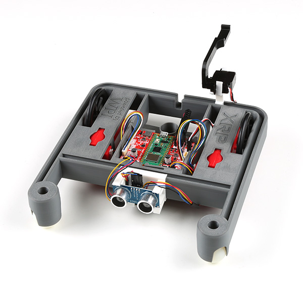
The image below shows the 3D mounted clip with the Optical Tracking Sensor attached to an XRP:

Optical Tracking Sensor Mounted to the XRP
Here is the underside of the XRP with the Optical Tracking Sensor attached via the mounting clip:

Optical Tracking Sensor Mounted to the XRP
Attention
Reminder - make sure you peel off the yellow kapton tape!

Peel off the Kapton tape before use
Hardware Assembly - FTC
The SparkFun Optical Tracking Odometry Sensor needs to be rigidly mounted to a robot chassis and oriented flat to the floor in order to get accurate data. If you don't already have a mount, there are a few 3D printing models you can use. That said, you may need to design your own mount for this board, depending on your use case.
Note here that we are using the foam surface typical of FIRST Tech Challenge competitions and the sensor is mounted at 10mm from the surface.
Warning
Accurate readings require that the sensor is mounted correctly; attempting to move the sensor by hand may work, but tracking accuracy will suffer.
The FTC mounts are available on Onshape with instructions for them here.
The image below shows the 3D mounted clip with the Optical Tracking Sensor attached to an FTC Bot:

Optical Tracking Sensor Mounted to the FTC Bot
FIRST Tech Challenge

FIRST Tech Challenge: Note here that for the foam competition files, the sensor really needs to be mounted at exactly 10mm from the surface with a tolerance of +/ 1mm. Beyond that, the tracking is less accurate; beyond +/- 3mm, and it can't track the foam surface at all.
Here is the underside of the FTC Bot with the Optical Tracking Sensor attached via the mounting clip:

Optical Tracking Sensor Mounted to the FTC Bot
Using the Flexible Qwiic to STEMMA Cable - 500mm, you'll need to attach the sensor via one of the I2C connectors on the Control Hub like so:

I2C connection location
Attention
Reminder - make sure you peel off the yellow kapton tape!
Peel off the Kapton tape before use
Software Setup - Arduino
Attention
If this is your first time using Arduino, please review our tutorial on installing the Arduino IDE. If you have not previously installed an Arduino library, please check out our installation guide.
We've written a library to get you started with the SparkFun Optical Tracking Odometry Sensor. You can obtain this library through the Arduino Library Manager by searching for "Odometry" and installing the latest version from SparkFun. If you prefer downloading libraries manually, you can grab them from the GitHub Repository.
In addition to the library provided here, we have written a Python script that allows you to visualize the XRP in real time. Download via the button below.

Visualization Script in Action
Software Setup - Python
Attention
If this is your first time working with Python, there are quite a few useful tutorials on getting started. The Python Programming Section of our Getting Started with the Raspberry Pi Tutorial has some good basic information and resources for getting started with Python.
Linux/Raspberry Pi Variants
We've written a python package to get you started with the SparkFun Optical Tracking Odometry Sensor. It's been included in the SparkFun Qwiic Python package, which aggregates all Python Qwiic drivers/modules to provide a single entity for Qwiic within a Python environment. The Qwiic_Py GitHub Library ReadMe has more information on the Qwiic Python package.
If you already have your Qwiic Python package installed, you can update it with the following command:
If you don't have the Qwiic Python package installed already, you can install it with the following command:
If you prefer to install just this package, use the following command:
If you prefer downloading the code to build and install the package manually, you can grab them from the GitHub Repository.
Attention
If you are working with a Raspberry Pi and are using the new Bookworm distribution of the Raspberry Pi OS, refer to these instructions to setup a virtual environment.
Make sure to include the --system-site-packages flag:python3 -m venv
Then it is possible to install the packages using pip.
XRP/MicroControllers
If you are working with the XRP or other microcontroller, pip will not work for you. Instead, you'll need to install the Qwiic_I2C_Py driver as well as the Qwiic_OTOS driver.
Attention
These instructions are written for the XRP using the XRPCode IDE. However the setup process is very similar for MicroPython and CircuitPython on any other board, so you should be able to follow along with these instructions using your IDE of choice!
Install Qwiic_I2C_Py
Qwiic_I2C_Py is a generic I2C driver we have created to work on various platforms (such as MicroPython). Our Qwiic Python device drivers take advantage of Qwiic_I2C_Py to function correctly on any of the supported platforms, so it is a required dependency to use our OTOS Python driver.
Fist, go to the Qwiic_I2C_Py repository and download it as a .zip file. Once downloaded, extract the qwiic_i2c folder within.
Connect your XRP to your computer over USB, navigate to the XRPCode IDE, and connect to your XRP. For usage information, see the XRPCode User Guide.
Create a new folder within the lib directory (right-click on the folder), and name it qwiic_i2c.

Create a new folder in the lib directory

Name the folder qwiic_i2c
Upload the files from the previously extracted qwiic_i2c folder into the new folder you just created on the XRP. From the File menu, choose the Upload to XRP option:

Choose the "Upload to XRP" option
Then select the extracted files:

Select the extracted I2C Files
Then choose the newly created qwiic_i2c folder on the XRP:

Choose the newly created qwiic_i2c folder
Uploading...

Update in Progress
You can test to confirm correct installation by typing import qwiic_i2c followed by qwiic_i2c.get_i2c_driver().scan() in the Shell. If no errors are printed, then the Qwiic_I2C_Py driver has been installed correctly!

Testing the install
Install Qwiic_OTOS_Py
Fist, go to the Qwiic_OTOS_Py repository and download just the qwiic_otos.py file.
Connect your XRP to your computer over USB, navigate to the XRPCode editor, and connect to your XRP. For usage information, see the XRPCode User Guide.
Upload the qwiic_otos.py file into the lib folder on the XRP. From the File menu, choose the Upload to XRP option:
Select the "Upload to XRP" Option from the File Menu
Select the qwiic_otos.py file:

Select the qwiic_otos.py file
Then select the lib folder on the XRP:

Select the lib folder on the XRP
Updating...
Updating
You can test to confirm correct installation by typing import qwiic_otos followed by qwiic_otos.QwiicOTOS().is_connected() in the Shell. If no errors are printed, then the Qwiic_OTOS_Py driver has been installed correctly!
Testing the install:

Testing the install
Visualization
In addition to the package provided here, we have written a Python script that allows you to visualize the XRP in real time. Download via the button below.
Visualization Script in Action
Software Setup - FIRST Tech Challenge Java
Update the FTC Robot Controller
Attention
Version v9.2 of the FTC SDK added our Java driver, so it is no longer necessary to manually install those files. Make sure you have at least v9.2 installed on your Control Hub before continuing!
Hardware Configuration
You can edit your robot's hardware configuration from the Driver Station. Select the I2C port that the OTOS is connected to, then tap the "Add" button. From the dropdown, you should see "SparkFun OTOS" like so:

Hardware Configuration
Warning
If you don't see "SparkFun OTOS" in the dropdown, make sure you have updated your Control Hub to use at least version v9.2 of the FTC SDK.
Then enter a name for the sensor. The sample OpMode assumes it is named sensor_otos, so that is recommended.
Once done, save your hardware configuration, then you're ready to run the sample OpMode!
Troubleshooting Tips
A few things we've noticed:
Calibration
Got the spins? If the IMU isn't calibrated correctly, the gyroscope will think the robot is constantly rotating and you may see something like below. If you find this, try re-calibrating your bot.

Example of Calibration Error
Note
Not working as expected and need help?
If you need technical assistance and more information on a product that is not working as you expected, we recommend heading on over to the SparkFun Technical Assistance page for some initial troubleshooting.
If you don't find what you need there, the SparkFun Forums are a great place to find and ask for help. If this is your first visit, you'll need to create a Forum Account to search product forums and post questions.
Resources:
For more resources related to the SparkFun SparkFun Optical Tracking Odometry Sensor, check out the links listed here:
- Product Page
- Schematic (PDF)
- Eagle Files (ZIP)
- Board Dimensions(PNG)
- Hardware GitHub Repository
- Optical Tracking Odometry Sensor Register Map (PDF)
Libraries/Packages:
- Arduino Library GitHub Repository
- SparkFun Optical Tracking Odometry Sensor Python Package GitHub
- SparkFun Optical Tracking Odometry Sensor Java Library GitHub
Visualization Python Script:
XRP Resources:
First Tech Challenge Resources:
Datasheets: