Quickstart Guide
In this Quick Start guide we'll show how to get air quality measurements from the SparkFun Air Quality PM1/PM2.5/PM10 Sensor - BMV080 (Qwiic) and IoT RedBoard - ESP32 using the Arduino IDE. This guide assumes users are familiar with the Arduino IDE and Arduino development boards. You'll need the following items to follow along with this guide:
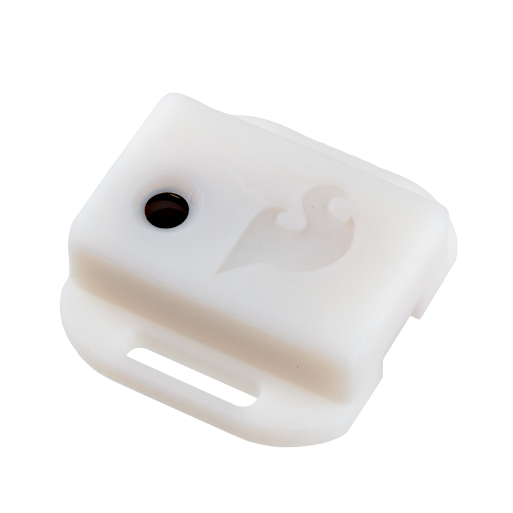
- SparkFun Air Quality PM2/PM2.5/PM10 Sensor - BMV080 (Qwiic)
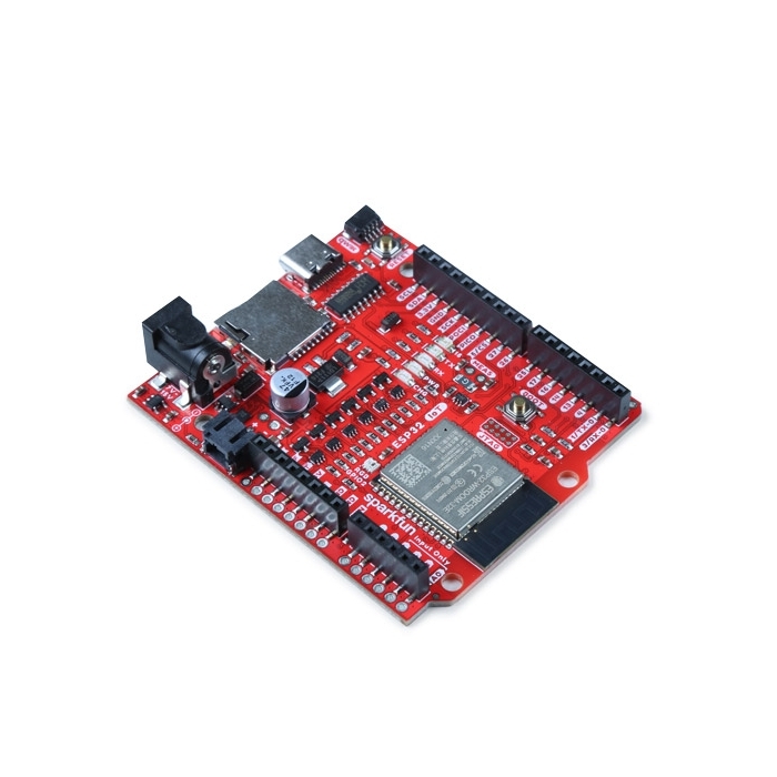
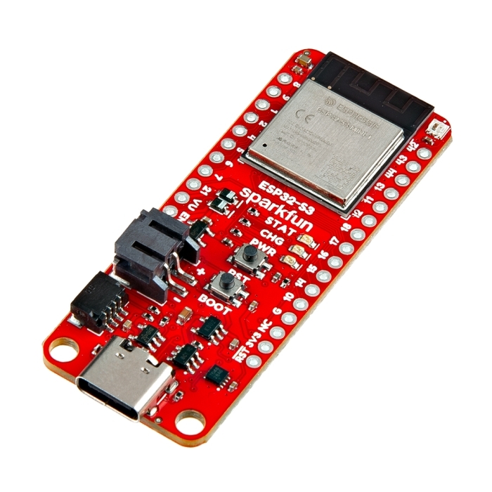
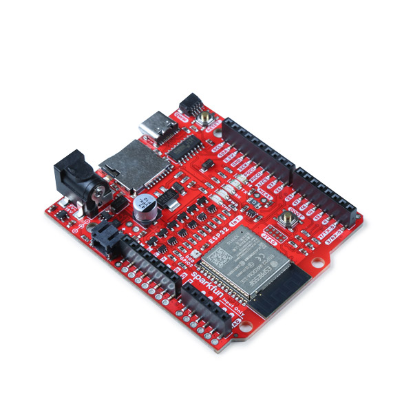
- SparkFun IoT RedBoard - ESP32
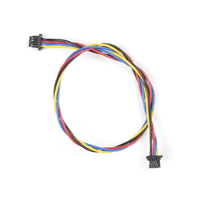
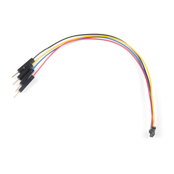
- Qwiic Cable
- USB-C Cable
If you're unfamiliar with any of the concepts covered here or would like more information about the Air Quality PM1/PM2.5/PM10 Sensor - BMV080 (Qwiic) read on to the following sections for detailed information about the BMV080 along with instructions on assembling it into a circuit, removing the breakout board from the enclosure and installing and using the BMV080 Arduino library.
Basic Assembly
Start by connecting the Air Quality Sensor - BMV080 to the IoT RedBoard - ESP32 using a Qwiic cable and then connect the IoT RedBoard - ESP23 to your computer with a USB-C cable:

Installing SparkFun BMV080 Arduino Library & Bosch BMV080 SDK Files
The SparkFun BMV080 Arduino library requires some manual installation as it does not include the required files from BMV080 SDK from Bosch. Users will need to download the SDK from this page and then manually place the necessary files in the SparkFun BMV080 Arduino library folder. The tables below outlines where to find the Arduino Libraries folder along with the filepaths and filenames of all SDK files you'll need to copy into the SparkFun BMV080 Arduino folder:
Library Install Directory
| OS | Directory |
|---|---|
| macOS | $HOME/Documents/Arduino/libraries/SparkFun_BMV080_Arduino_Library |
| Windows | $HOME\Documents\Arduino\libraries\SparkFun_BMV080_Arduino_Library |
| Linux | $HOME/Arduino/libraries/SparkFun_BMV080_Arduino_Library |
Files to copy and locations to copy to
From the Bosch SDK, the following files are copied into the specified library locations.
| Bosch SDK File | SparkFun BMV080 Arduino Library Directory |
|---|---|
| api/inc/bmv080.h | src/sfTk/bmv080.h |
| api/inc/bmv080_defs.h | src/sfTk/bmv080_defs.h |
| api/api/lib/xtensa_esp32/xtensa_esp32_elf_gcc/release/lib_bmv080.a | src/esp32/lib_bmv080.a |
| api/api/lib/xtensa_esp32/xtensa_esp32_elf_gcc/release/lib_postProcessor.a | src/esp32/lib_postProcessor.a |
| api/api/lib/xtensa_esp32s2/xtensa_esp32s2_elf_gcc/release/lib_postProcessor.a | src/esp32s2/lib_postProcessor.a |
| api/api/lib/xtensa_esp32s2/xtensa_esp32s2_elf_gcc/release/lib_bmv080.a | src/esp32s2/lib_bmv080.a |
| api/api/lib/xtensa_esp32s3/xtensa_esp32s3_elf_gcc/release/lib_postProcessor.a | src/esp32s3/lib_postProcessor.a |
| api/api/lib/xtensa_esp32s3/xtensa_esp32s3_elf_gcc/release/lib_bmv080.a | src/esp32s3/lib_bmv080.a |
| api/api/lib/arm_cortex_m0plus/xarm_none_eabi_gcc/release/lib_postProcessor.a | src/cortex-m0plus/lib_postProcessor.a |
| api/api/lib/arm_cortex_m0plus/arm_none_eabi_gcc/release/lib_bmv080.a | src/cortex-m0plus/lib_bmv080.a |
| api/api/lib/arm_cortex_m33f/xarm_none_eabi_gcc/release/lib_postProcessor.a | src/cortex-m33/lib_postProcessor.a |
| api/api/lib/arm_cortex_m33f/arm_none_eabi_gcc/release/lib_bmv080.a | src/cortex-m33/lib_bmv080.a |
| api/api/lib/arm_cortex_m4/xarm_none_eabi_gcc/release/lib_postProcessor.a | src/cortex-m4/lib_postProcessor.a |
| api/api/lib/arm_cortex_m4/arm_none_eabi_gcc/release/lib_bmv080.a | src/cortex-m4/lib_bmv080.a |
| api/api/lib/arm_cortex_m4f/xarm_none_eabi_gcc/release/lib_postProcessor.a | src/cortex-m4f/lib_postProcessor.a |
| api/api/lib/arm_cortex_m4f/arm_none_eabi_gcc/release/lib_bmv080.a | src/cortex-m4f/lib_bmv080.a |
Arduino Example 1 - Basic Readings
This example demonstrates the basics of initializing and reading air quality data from the BMV080 over I2C. Run "Example 01 - Basic Readings" by completing the following steps:
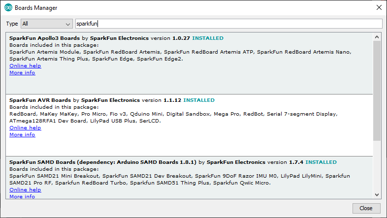
- If necessary, open the Boards Manager tool, search for "SparkFun ESP32" and install the latest version of the SparkFun ESP boards.
- In the Examples menu, open Example_01_BasicReadings.
- Select the Board (SparkFun ESP32 IoT RedBoard) and Port and click "Upload".
- Open the Serial Monitor with the baud set to 115200 to view particulate matter readings from the BMV080.

Introduction
The SparkFun Qwiic Air Quality PM1/PM2.5/PM10 Sensor - BMV080 is an ultra-small, fan-less air quality sensor for sensing PM1 and PM2.5 particulate matter! Within the enclosure is a breakout board that breaks out Bosch's BMV080, the world's smallest PM1, PM2.5 and PM10 air quality sensor. The sensing element measures merely 4.2mm x 3.5mm x 3.1mm (W x L x H), which is more than 450 times smaller than any comparable device on the market. The innovative design is based on ultra-compact lasers with integrated photodiodes. The sensor applies sophisticated algorithms to measure PM1, PM2.5 and PM10 concentrations directly in free space, without requiring an intrusive fan.
In this tutorial, we'll go over the hardware and how to hookup the sensor to an Arduino. We will also go over examples from the Arduino Library to get started.
Required Materials
This tutorial is written to use the SparkFun Particulate Matter Sensor - BMV080 with the SparkFun IoT RedBoard - ESP32. If you want to follow along exactly with the tutorial, you'll need the BMV080 along with the following items:
Other Microcontrollers
We recommend using any board with an ESP32 (such as the ESP32-WROOM, ESP32-S2, and ESP32-S3). We'll be using the RedBoard IoT RedBoard - ESP32 Development Board for the examples in this tutorial.
Qwiic Accessories
For those that want to take advantage of the Qwiic connector, you'll want to grab a Qwiic cable. Besides the one listed earlier, there are a variety of other cable lengths available in the SparkFun catalog to choose from.
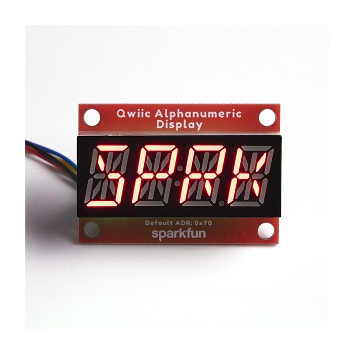
You'll also want a Qwiic MultiPort when daisy chaining more than one BMV080 or adding additional Qwiic-enabled devices. Adding displays will allow you to view the amount of particulate mater in the air.
Tools (Optional)
Note
When soldering directly to the PTHs, you will need to be careful of the 3D printed enclosure! You will want to carefully remove the board from the enclosure before soldering.
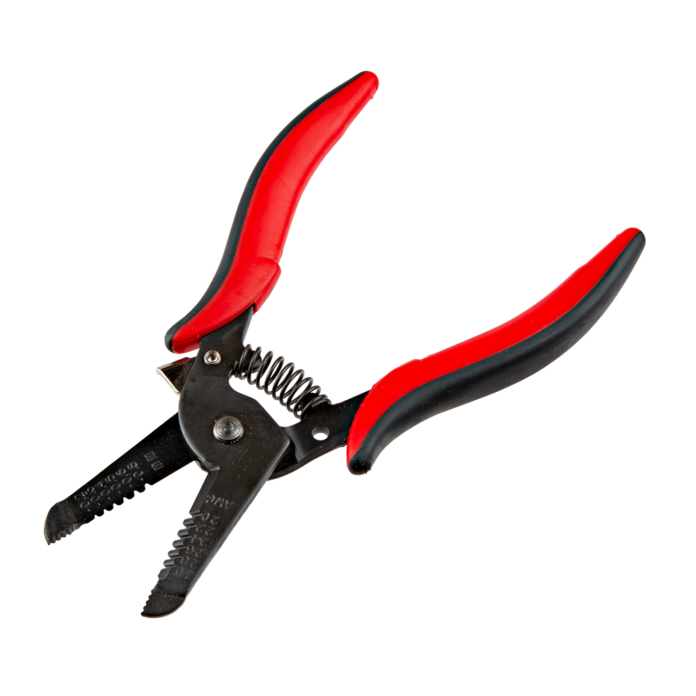
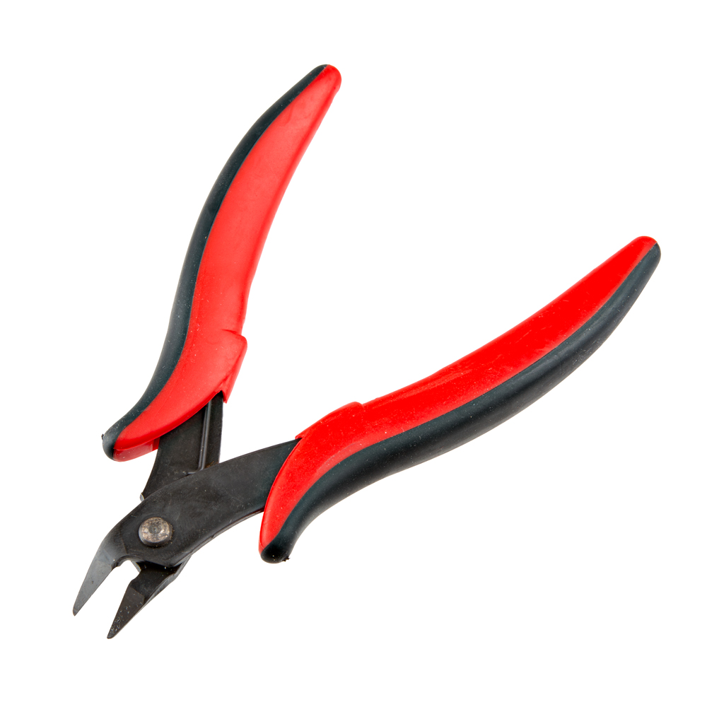
You will need a soldering iron, solder, and general soldering accessories for a secure connection when using the plated through holes.
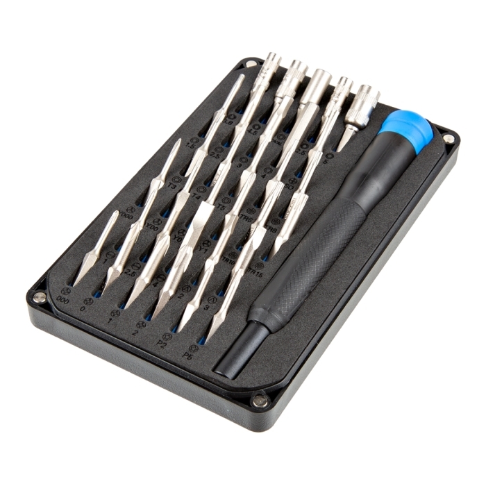
For users that are using the BMV080 in SPI mode or mounting the enclosure, make sure to grab the iFixit Moray Driver Kit. A precision flathead with 0.1mm tip is needed to remove the sensor from the enclosure. We also recommend using Phillips screwdriver with #0 tip and 4-40 standoffs when mounting the enclosure.
Prototyping Accessories (Optional)
Note
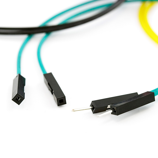
Due to the size of the 3D printed enclosure, you will not be able to place the sensor on a breadboard. We recommend using M/F jumper wires should you decide to solder male header pins on the sensor. Of course, when soldering the sensor to a protoboard, you could solder to the other side of the protoboard to access the pins.
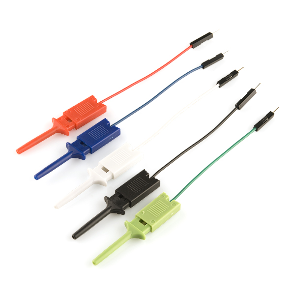
Depending on your setup, you may want to use IC hooks for a temporary connection when the sensor is removed from enclosure. However, you will want to solder header pins to connect devices to the plated through holes for a secure connection. We opted for straight male headers for the SparkFun Qwiic Air Quality PM1/PM2.5/PM10 Sensor - BMV080 as well as M/F jumpers to connect to the RedBoard IoT Development Board to reduce the amount of soldering.
Suggested Reading
If you aren't familiar with the Qwiic Connection System, we recommend reading here for an overview.
If you aren’t familiar with the following concepts, we also recommend checking out a few of these tutorials before continuing.
Hardware Overview
In this section, we will highlight the hardware and pins that are broken out on the SparkFun Qwiic Air Quality PM1/PM2.5/PM10 Sensor - BMV080. For more information, check out our Resources and Going Further on the components used for the sensor.

BMV080
The breakout board comes with Bosch's BMV080 populated and takes advantage of its flexible cable with the FPC 13-pin 0.33mm connector. The sensor is an ultra-small, fan-less air quality sensor for sensing PM1, PM2.5 and PM10 concentrations. A special lens allows the laser to pass through the enclosure to take measurements.
Note
This is a CLASS 1 LASER PRODUCT CLASSIFIED IEC 60825-1 2014.
Power
To power the board, you will need 3.3V. You can connect a Qwiic cable to the Qwiic connector. Or you could solder directly to the PTHs. Below are the power pins that are broken out on the edge of the board.
- 3V3 - This pin is the voltage input for the board. The recommended input voltage for this pin is 3.3V.
- GND - Of course, is the common, ground voltage (0V reference) for the system.
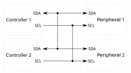
Qwiic and I2C
By default, the communication interface is set to I2C with the MODE jumper. The board includes one horizontal Qwiic connector to connect to other Qwiic-enabled I2C devices. However, the board still breaks out 0.1"-spaced pins for users who prefer a soldered connection.
- SCL/SCK - On the top side, the pin is labeled as SCL. On the bottom side, the pin is labeled as SCK. Thus the pin is used for the I2C clock.
- SDA/PICO - On the top side, the pin is labeled as SDA. On the bottom side, the pin is labeled as PICO. Thus the pin is used for the I2C data.
The default address of the BMV080 is set to 0x57 by default. By configuring AB1 and AB0 jumpers, you can adjust the I2C address to an alternative address. For more information, check below under the jumpers.
Interrupt Pin
The board includes an interrupt pin when the board is set to I2C mode.
- IRQ — Short for interrupt. This pin sends an interrupt signal to a microcontroller.
Note
The hardware interrupt of the BMV080 sensor unit cannot be used as trigger in duty cycling mode.
SPI
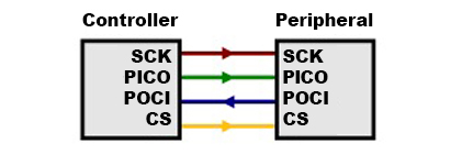
The BMV080 can also be set to SPI as the communication interface by adjusting the MODE jumper on the back.
- PICO/SDA - On the bottom side, the pin is labeled as PICO (i.e. Peripheral In, Controller Out). On the top side, the pin is labeled as SDA.
- POCI/AB0 - On the bottom side, the pin is labeled as POCI (i.e. Peripheral Out, Controller In). On the top side, the pin is labeled as AB0. When set to SPI mode, make sure to leave AB0 (POCI) open!
- SCK/SCL - On the bottom side, the pin is labeled as SCK for the clock. On the tip side, the pin is labeled as SCL.
- CS - On the bottom side, the pin is labeled as CS (i.e. chip select). On the top side, the pin is labeled as AB1. This pin is active low. When set to SPI mode, make sure to leave AB1 (CS) open!
Jumpers
Note
If this is your first time working with jumpers, check out the How to Work with Jumper Pads and PCB Traces tutorial for more information.
The back of the board has four jumpers to configure the board labeled I2C, AB0, AB1 and MODE.
- I2C - By default, this three-pad jumper is closed. The three way jumper labeled I2C connects 3.3V to two 2.2kΩ pull-up resistors and to the I2C data and clock lines. If multiple devices are connected to the bus with the pull-up resistors enabled, the parallel equivalent resistance will create too strong of a pull-up for the bus to operate correctly. As a general rule of thumb, disable all but one pair of pull-up resistors if multiple devices are connected to the bus.
- AB0 - Address jumper 0 when the BMV080 is set to I2C mode. This is a multifunctional pin. This is also connected to POCI. By default, the three-pad jumper's center pad is connected to the
1side - AB1 - Address jumper 1 when the BMV080 is set to I2C mode. This is a multifunctional pin. This is also connected to CS. By default, the three-pad jumper's center pad is connected to the
1side - MODE - By default, this three-pad jumper is closed between the center pad and the pad labeled as I2C. Thus, the communication interface is set to I2C. Cutting this trace and adding solder between the center pad and the pad labeled as SPI will configure the communication interface as SPI.
When the SparkFun Qwiic Air Quality Sensor is configured in I2C mode, users have the ability to configure the default address using AB0 and AB1 jumpers. The following table shows the possible I2C address based on the jumper configuration.
| AB1 | AB0 | I2C Address |
|---|---|---|
| 0 | 0 | 0x54 |
| 0 | 1 | 0x55 |
| 1 | 0 | 0x56 |
| 1 | 1 | 0x57 (default) |
Note
AB0 is a multifunctional pin! When the SparkFun Qwiic Air Quality Sensor is configured for SPI, make sure to leave AB0 (POCI) open!
3D Model
A 3D model of the board and components was exported to a STEP file using KiCad.
Board Dimensions
The board measures 0.5" x 0.95" (12.70mm x 24.13mm). The breakout board itself does not have mounting holes though the enclosure has two mounting slots to attach the sensor to your project.

Hardware Hookup
Connecting via Qwiic
By default, the sensor can be read through I2C. Connect a Qwiic cable between the SparkFun Qwiic Air Quality Sensor and your microcontroller. Then connect a compatible USB cable between the microcontroller and your computer's USB port.

Removing the BMV080 from the enclosure
The Air Quality PM1/PM2.5/PM10 Sensor - BMV080 (Qwiic) comes housed in an enclosure to help protect the sensor during handling and installation. The enclosure does expose the solder jumpers and PTH pins for users to access while the board is inside the enclosure. While it is possible to access these parts of the board, we recommend removing the breakout from the enclosure prior to working with either the solder jumpers or PTH pins.
We strongly recommend putting on Latex or Nitrile gloves (and not following our bad example in the photos below) before removing the board from the enclosure. Also, make sure to perform these steps on a clean and flat surface. Whether or not you decide to use gloves, do your best to avoid touching the enclosure's glass sensor cover and do not touch the bare sensor or any of the passive components (resistors/capacitors) near it:

Start by identifying the two slots on either side of the enclosure. Next, carefully slide a precision flathead screwdriver or similar precise tool into one of the slots and gently wedge it under the tab. Rock the precision flathead's handle toward the mounting hole so the tab pops out.

Repeat this step on the other side to "unlock" the two pieces of the enclosure, then carefully remove the outer shell of the enclosure.

Next, identify the rubber O-ring and lens cover (beneath the O-ring) covering the BMV080 aperture. Using tweezers, first remove the O-ring and then the lens cover. Make sure to place them on a clean surface to avoid contaminating them with dust or other substances:


With the O-ring and lens cover removed, the assembly should look like the photo below:

The inner shell of the enclosure has a small notch to lock the breakout board into place inside. Using either your fingertip or tweezers, gently press down on the edge of the breakout board while pressing from the other side to slide the board out from the inner shell.

Slide the sensor out from the inner shell's slot while taking care to avoid touching the BMV080 sensor and passive components on the sensor's ribbon cable.

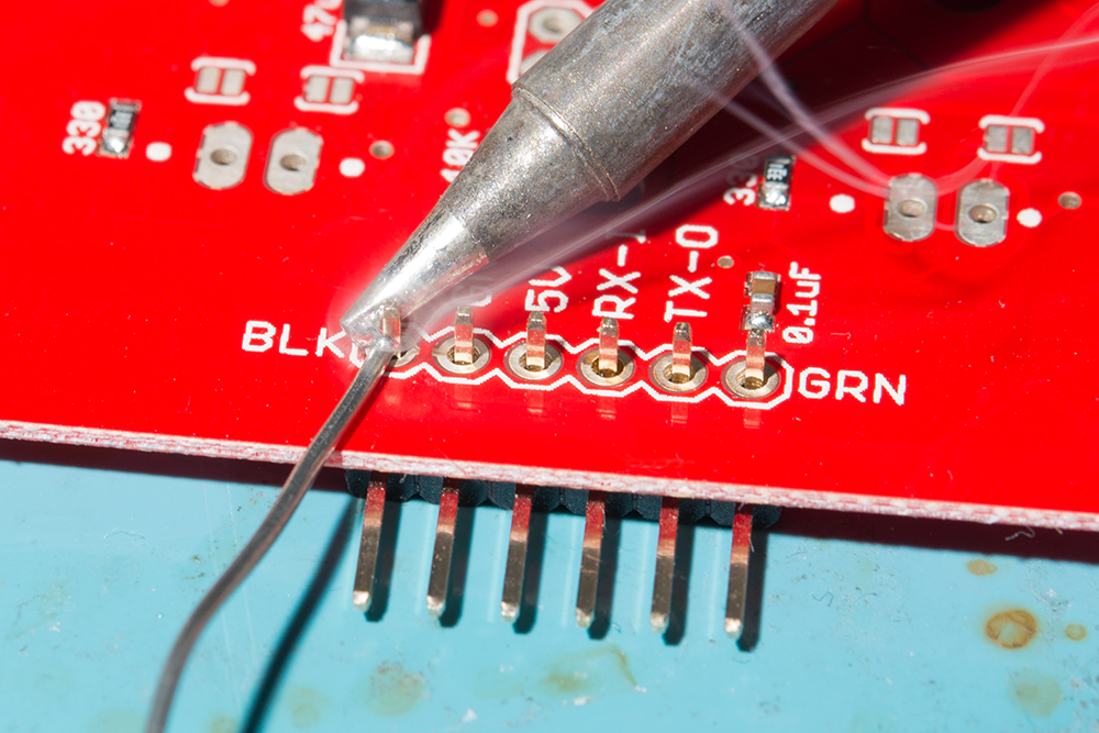
Now that the breakout board is out of the enclosure we can solder to the board and adjust the solder jumpers. If using male header pins, solder the short end from the top side of the board so that you can access the longer mating pins from the bottom side. If you're soldering wires, make sure to trim the leads as short as possible to avoid obstructing the board from sliding back into the enclosure. After soldering, carefully clean the solder joints to remove any flux residue left on the board using isopropyl alcohol and a Q-tip or other gentle cleaning tool.
Note
When soldering make sure to not add too much solder. Excess solder can obstruct the breakout board from sliding back into the inner shell. For users soldering header pins, ensure that the header's plastic spacer is flush against the breakout board and not at an angle. For users soldering wire, ensure that the stripped wire is short.
Reassembling the Enclosure
Once we're done modifying the breakout board we'll want to place the sensor back in the enclosure. This section goes over how to reassemble the parts but essentially we're just working backward through the previous steps.
Start by sliding the BMV080 breakout board back into the inner shell until it "clicks" back into place once it is past the notch. Make sure the BMV080 sensor and the Qwiic connector align with their respective apertures in the inner shell:

Turn the enclosure over on a clean, flat surface. Using tweezers, place the lens cover over the hole where the BMV080's sensor is located. Then place the o-ring over lens cover. Ensure that the parts are in their respective square and circular slots.


Now take the outer shell and place it back onto the inner shell making sure to align the apertures for the BMV080 and Qwiic connectors. Push down until you hear the tabs pop in.


Connecting via PTH
Note
When soldering directly to the PTHs, you will need to be careful of the 3D printed enclosure! You will want to carefully remove the board from the enclosure when soldering.
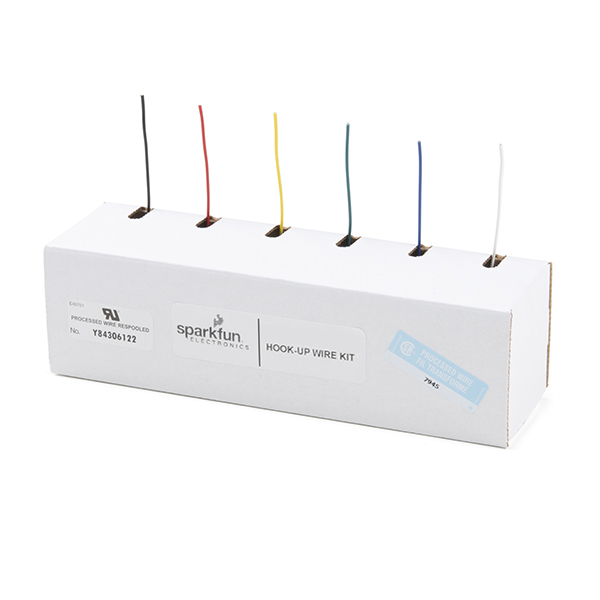
For temporary connections to the PTHs, you could use IC hooks to test out the pins. However, you'll need to solder headers or wires of your choice to the board for a secure connection. You can choose between a combination of header pins and jumper wires, or stripping wire and soldering the wire directly to the board.
Interrupt
The following table shows the connection that is required between an ESP32 and the SparkFUn Qwiic Air Quality Sensor when using I2C as the communication interface with interrupts.
| ESP32 Pinout (i.e. IoT RedBoard - ESP32, ESP32 Thing Plus C, etc.) |
SparkFun Qwiic Air Quality Sensor BMV080 |
|---|---|
| GND | GND |
| 3.3V | 3V3 |
| SDA | SDA (PICO) |
| SCL | SCL (SCK) |
| 14 | IRQ |
SPI
The following tables shows the connection that is required between between an ESP32 and the SparkFun Qwiic Air Quality Sensor when using SPI as the communication interface. You will need to cut the MODE jumper between the center pad and the pad labeled as I2C. Then add solder between the center pad and the pad labeled as SPI. Make sure to also leave the AB0 jumper open (i.e. both sides of the jumper are not connected).
| ESP32 Pinout (i.e. IoT RedBoard - ESP32, ESP32 Thing Plus C, etc.) |
SparkFun Qwiic Air Quality Sensor BMV080 |
|---|---|
| GND | GND |
| 3.3V | 3V3 |
| PICO | PICO (SDA) |
| POCI | POCI (AB0) |
| SCK | SCK (SCL) |
| CS | CS (AB1) |

Setting Up Arduino
Arduino
This example assumes you are using the latest version of the Arduino IDE on your desktop. If this is your first time using Arduino IDE, library, or board add-on, please review the following tutorials.
SparkFun BMV080 Arduino Library Install
SparkFun has written a library using Bosch's API to work with the BMV080! You can obtain this library through the Arduino Library Manager by searching for "SparkFun BMV080". Find the one written by SparkFun Electronics and install the latest version. Users who prefer to manually install the library can get it from the GitHub Repository or download the .ZIP by clicking the button below:
Note
The SparkFun BMV080 Arduino Library uses the SparkFun Toolkit as a dependency. This should automatically download when installing the library using the Arduino Library Manager. For users that are installing the BMV080 library manually, make sure to download the SparkFun Toolkit as well. At the time of writing, we were using the following Arduino Libraries, firmware binaries, board add-ons.
- Arduino Libraries
- SparkFun BMV080 Arduino Library
- SparkFun Toolkit v1.0.0
- Board Definitions
- esp32 by Espressif v3.0.1 for the IoT RedBoard - ESP32.
Adding the BMV080 SDK
The SparkFun BMV080 Arduino library requires some manual installation as it does not include the required files from BMV080 SDK from Bosch. After installing the SparkFun library, users need to download the SDK from this page and then manually place the necessary files in the SparkFun BMV080 Arduino library folder. The tables below outlines where to find the Arduino Libraries folder along with the filepaths and filenames of all SDK files you'll need to copy into the SparkFun BMV080 Arduino folder:
Library Install Directory
| OS | Directory |
|---|---|
| macOS | $HOME/Documents/Arduino/libraries/SparkFun_BMV080_Arduino_Library |
| Windows | $HOME\Documents\Arduino\libraries\SparkFun_BMV080_Arduino_Library |
| Linux | $HOME/Arduino/libraries/SparkFun_BMV080_Arduino_Library |
Files to copy and locations to copy to
From the Bosch SDK, the following files are copied into the specified library locations.
| Bosch SDK File | SparkFun BMV080 Arduino Library Directory |
|---|---|
| api/inc/bmv080.h | src/sfTk/bmv080.h |
| api/inc/bmv080_defs.h | src/sfTk/bmv080_defs.h |
| api/api/lib/xtensa_esp32/xtensa_esp32_elf_gcc/release/lib_bmv080.a | src/esp32/lib_bmv080.a |
| api/api/lib/xtensa_esp32/xtensa_esp32_elf_gcc/release/lib_postProcessor.a | src/esp32/lib_postProcessor.a |
| api/api/lib/xtensa_esp32s2/xtensa_esp32s2_elf_gcc/release/lib_postProcessor.a | src/esp32s2/lib_postProcessor.a |
| api/api/lib/xtensa_esp32s2/xtensa_esp32s2_elf_gcc/release/lib_bmv080.a | src/esp32s2/lib_bmv080.a |
| api/api/lib/xtensa_esp32s3/xtensa_esp32s3_elf_gcc/release/lib_postProcessor.a | src/esp32s3/lib_postProcessor.a |
| api/api/lib/xtensa_esp32s3/xtensa_esp32s3_elf_gcc/release/lib_bmv080.a | src/esp32s3/lib_bmv080.a |
| api/api/lib/arm_cortex_m0plus/xarm_none_eabi_gcc/release/lib_postProcessor.a | src/cortex-m0plus/lib_postProcessor.a |
| api/api/lib/arm_cortex_m0plus/arm_none_eabi_gcc/release/lib_bmv080.a | src/cortex-m0plus/lib_bmv080.a |
| api/api/lib/arm_cortex_m33f/xarm_none_eabi_gcc/release/lib_postProcessor.a | src/cortex-m33/lib_postProcessor.a |
| api/api/lib/arm_cortex_m33f/arm_none_eabi_gcc/release/lib_bmv080.a | src/cortex-m33/lib_bmv080.a |
| api/api/lib/arm_cortex_m4/xarm_none_eabi_gcc/release/lib_postProcessor.a | src/cortex-m4/lib_postProcessor.a |
| api/api/lib/arm_cortex_m4/arm_none_eabi_gcc/release/lib_bmv080.a | src/cortex-m4/lib_bmv080.a |
| api/api/lib/arm_cortex_m4f/xarm_none_eabi_gcc/release/lib_postProcessor.a | src/cortex-m4f/lib_postProcessor.a |
| api/api/lib/arm_cortex_m4f/arm_none_eabi_gcc/release/lib_bmv080.a | src/cortex-m4f/lib_bmv080.a |
BMV080 Board Limitations
The SparkFun BMV080 Arduino Library only works with the following SparkFun boards:
- IoT RedBoard - ESP32
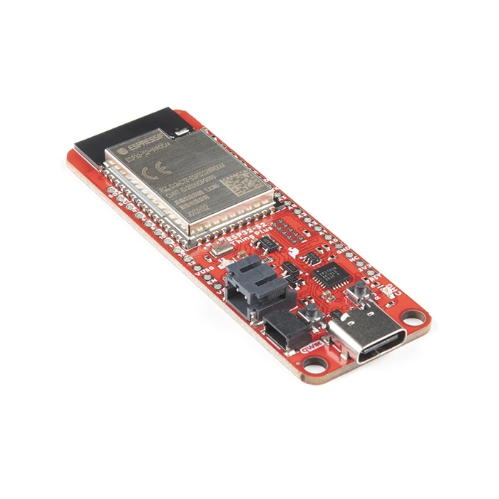
- Thing Plus - ESP32 WROOM (USB-C)
- Thing Plus - ESP32-S2 WROOM
- Thing Plus - RA6M5
Now that we have our library and board add-on installed, we can start experimenting with the breakout board. For the scope of this tutorial, we will highlight the examples to get started. From there we will be able to build our own custom code to integrate the development board into a project.
Arduino Example 1 — Basic Readings
This example shows how to read the BMV080 via Qwiic when the sensor is configured in continuous mode. The output will show the amount of particulate matter that is detected.
Head to the example 1 from the Arduino IDE's menu (located in File Examples > SparkFun BMV080 Arduino Library > Example_01_BasicReadings).
If you have not already, select your Board (if you're following along with the suggested dev board for this tutorial, select SparkFun ESP32 IoT RedBoard), and associated COM port. Upload the code to the board and set the Arduino Serial Monitor to 115200 baud. The Arduino should begin outputting the sensor readings. If the air in front of the sensor is void of particulate matter, you should see 0.00 for each size.

Try placing something like a scented candle or other source of particulate matter near the sensor. You should see the sensor readings jump up depending on the PM size. When the sensor detects an object in front of the it, the code prints out obstructed.
Arduino Example 2 — Duty Cycle
This example shows how to read the BMV080 via Qwiic when the sensor is configured in duty cycle mode. Similar to the first example, the output will show the amount of particulate matter that is detected. However, it will show the readings every 20 seconds.
Head to the example 2 from the Arduino IDE's menu (located in File Examples > SparkFun BMV080 Arduino Library > Example_02_DutyCycle).
If you have not already, select your Board and associated COM port. Upload the code to the board and set the Arduino Serial Monitor to 115200 baud. The Arduino should begin outputting the sensor readings every 20 seconds.
Arduino Example 3 — Interrupt
Note
The interrupt example cannot be used when the BMV080 is in duty cycling mode.
This example shows how to read the BMV080 via Qwiic when the sensor is configured in continuous mode with a hardware interrupt. Similar to the first example, the output will show the amount of particulate matter that is detected. However, the sensor will trigger a hardware interrupt.
Head to the example 3 from the Arduino IDE's menu (located in File Examples > SparkFun BMV080 Arduino Library > Example_03_Interrupt).
If you have not already, select your Board and associated COM port. Upload the code to the board and set the Arduino Serial Monitor to 115200 baud. The Arduino should begin outputting the sensor readings every 20 seconds.

Tip
You can view the timestamp of each sensor readings in the Arduino Serial Monitor by clicking on the "Toggle Timestamp" button. This button is represented as a clock above the baud rate.
Arduino Example 4 — SPI
Note
Make sure to configure the board for SPI mode by adjusting the jumpers on the back of the board. You will also need to solder headers to the board and wire to your Arduino's SPI port.
This example shows how to read the BMV080 via SPI when the sensor is configured to continuous mode.
Head to the example 4 from the Arduino IDE's menu (located in File Examples > SparkFun BMV080 Arduino Library > Example_04_SPI).
If you have not already, select your Board and associated COM port. Upload the code to the board and set the Arduino Serial Monitor to 115200 baud. The Arduino should begin outputting the sensor readings.
Arduino Example 5 — Parameters
This example shows how to read and set the parameters of the BMV080 via Qwiic. These include volumetric_mass_density, integration_time, distribution_id, do_obstruction_detection, do_vibration_filtering, and measurement_algorithm. Once these parameters are read and set, this example will then configure the sensor in continuous mode to read particulate mater every second.
Head to the example 5 from the Arduino IDE's menu (located in File Examples > SparkFun BMV080 Arduino Library > Example_05_Parameters).
If you have not already, select your Board and associated COM port. Upload the code to the board and set the Arduino Serial Monitor to 115200 baud. The Arduino should output the paraemters before outputting the sensor readings every second.

Note
If you do not see the parameters after uploading, you may not have opened the Arduino Serial Monitor when the Arduino output the parameters. Try restarting your Arduino by hitting the reset button.
Arduino Example 6 — Two Sensors
Note
Make sure to have one sensor using the alternate I2C address. In this case, the second BMV080 had AB0 jumper changed to 0.
This example shows how to read two BMV080 via Qwiic when each sensor is configured in continuous mode. The output will show the amount of particulate matter that is detected from both sensors.
Head to the example 6 from the Arduino IDE's menu (located in File Examples > SparkFun BMV080 Arduino Library > Example_06_TwoSensors).
If you have not already, select your Board and associated COM port. Upload the code to the board and set the Arduino Serial Monitor to 115200 baud. The Arduino should begin outputting the sensor readings from both BMV080s.

Arduino Example 7 — Qwiic Alphanumeric Display
This example shows how to read the BMV080 via Qwiic when the sensor is configured in duty cycle mode and outputs the readings to display them on a Qwiic Alphanumeric display connected over a Qwiic daisy-chain. You'll need a Qwii Alphanumeric Display to run this example.
Head to the example 7 from the Arduino IDE's menu (located in File Examples > SparkFun BMV080 Arduino Library > Example_07_Demo_Alphanumeric).
If you have not already, select your Board and associated COM port. Upload the code to the board and set the Arduino Serial Monitor to 115200 baud. The Arduino should begin outputting the sensor readings through the Arduino Serial Monitor and the Qwiic Alphanumeric display. For simplicity, we will only display PM2.5.
Arduino Example 8 — Qwiic OLED (1.3", 128x64)
This example shows how to read the BMV080 via Qwiic when the sensor is configured in duty cycle mode and outputs sensor data to a connected Qwiic OLED Display (specifically the 1.3", 128x64). You'll need a Qwiic OLED Display connected to the Qwiic circuit to run this example.
Head to the example 8 from the Arduino IDE's menu (located in File Examples > SparkFun BMV080 Arduino Library > Example_08_Demo_OLED).
If you have not already, select your Board and associated COM port. Upload the code to the board and set the Arduino Serial Monitor to 115200 baud. The Arduino should begin outputting the sensor readings through the Arduino Serial Monitor and the Qwiic OLED Display (1.3", 128x64).
Troubleshooting
Sensor Handling & Care
The BMV080's sensing apparatus is exceptionally sensitive and can be obstructed by small particles of dust along with any other substance present on either the sensor itself or the enclosure's protective lense such as oil from your fingers. Be very careful when handling the sensor to not touch the sensing area even when in the enclosure.
If the sensor reports any "obstruction" carefully clean the sensor using compressed air (recommended) or, if absolutely necessary, a clean, non-abrasive tissue.
General Troubleshooting Help
Note
Not working as expected and need help?
If you need technical assistance and more information on a product that is not working as you expected, we recommend heading on over to the SparkFun Technical Assistance page for some initial troubleshooting.
If you don't find what you need there, the SparkFun Forums are a great place to find and ask for help. If this is your first visit, you'll need to create a forum account to search product forums and post questions.
Resources
Now that you've successfully got your SparkFun Air Quality PM1/PM2.5/PM10 Sensor - BMV080 (Qwiic) up and running, it's time to incorporate it into your own project! For more information, check out the resources below:
- Schematic (PDF)
- KiCad Files (ZIP)
- Board Dimensions (PNG)
- 3D Model
- Component Datasheets
- Arduino Library
- GitHub Hardware Repo
