Introduction
-
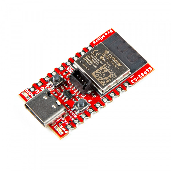
SparkFun Pro Micro - ESP32-C3
SKU: DEV-23484
-
Don't be fooled by its miniature size; the SparkFun Pro Micro ESP32-C3 packs a punch. This micro marvel crams the powerful ESP32-C3, a single-core RISC-V powerhouse with 400KB of SRAM, into a compact 1.3in. x 0.7in. board. Clocking in at 160MHz, it's ready to tackle your projects quickly and efficiently. Forget wires and soldering headaches – the Pro Micro ESP32-C3 embraces the simplicity of the Qwiic connector. Just plug and play any Qwiic sensor and watch your projects come alive with environmental data, motion detection, or whatever your imagination conjures. And stay connected, wherever you are, with built-in WiFi and Bluetooth® 5 (LE).
Purchase from SparkFun
Required Materials
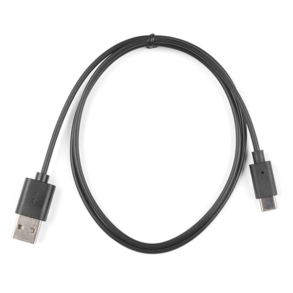
To get started, users will need a few items. You may already have a few of these items, feel free to modify your cart accordingly.
Suggested Reading
If you aren’t familiar with the following concepts, we recommend checking out these tutorials before continuing.
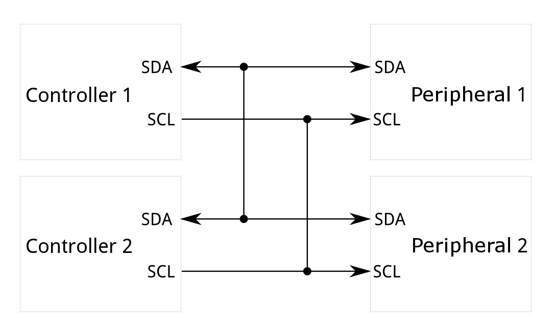

The SparkFun Pro Micro ESP32-C3 takes advantage of the Qwiic connect system. We recommend familiarizing yourself with the Logic Levels and I2C tutorials. Click on the banner above to learn more about Qwiic products.
Hardware Overview
ESP32 C3 WiFi Module
The ESP32-C3 from Espressif is a single-core, 32-bit, RISC-V-based MCU with 400KB of SRAM, which is capable of running at 160MHz. It has integrated 2.4 GHz Wi-Fi and Bluetooth 5 (LE) with a long-range support. It has 22 programmable GPIOs with support for ADC, SPI, UART, I2C, I2S, RMT, TWAI, and PWM. More information is available in the datasheet.

ESP32 C3 WiFi Module
Voltage Regulator - RT9080
The RT9080 regulates voltage to the various components of the board. Maximum input voltage should be no more than 5.5V.
Current Max: 600mA

Voltage Regulator - RT9080
Qwiic Connector
The board includes a Qwiic connector for use with our vast array of Qwiic sensors. For users that need to solder directly to the board, the pins are also broken out on the edge PTH. The I2C data and clock lines are also tied to 2.2kΩ pull-up resistors.

Qwiic Connector
JTAG
While most users will utilize the USB connection for programming, the ESP32-C3 can also be programmed through its JTAG or SWD pins. This is useful for individuals developing and debugging firmware that would be flashed directly onto the module, such as in production for commercial applications. We recommend soldering a 2x5 Male Pin header for use.

ESP32 JTAG pads
Castellated Headers
The castellated headers along either side of the board are useful for adding complex functionality like RF to a design, as well as being low profile and compact. If you've never worked with castellated headers, head on over to our Castellated Mounting Holes Tutorial for more information.

Castellated Headers
Buttons
There are two buttons on the board - Reset and Boot. The reset (RST) button allows users to reset the program running on the ESP32-C3 module without unplugging the board. The Boot Button allows the user to manually put the board into Bootloader Mode. To enter bootloader, hold the Boot button down when the ESP32 resets or powers on.

Boot and Reset Buttons
LEDs
Two LEDs - Power(Red) and STAT(Blue) - show the user that power has been appropriately supplied to the board and the status of the data transfer.

Power and Status LEDs
Jumpers
Never modified a jumper before?
Check out our Jumper Pads and PCB Traces tutorial for a quick introduction!

I2C Jumper
If you choose to use one or more Qwiic breakouts in your project, it is important to note that this board comes equipped with pull-up resistors on the clock and data pins. If you are daisy-chaining multiple Qwiic devices, you will want to cut this jumper; if multiple sensors are connected to the bus with the pull-up resistors enabled, the parallel equivalent resistance will create too strong of a pull-up for the bus to operate correctly. As a general rule of thumb, disable all but one pair of pull-up resistors if multiple devices are connected to the bus. To disable the pull up resistors, use an X-acto knife to cut the joints between theWS jumper pads highlighted below.

I2C Jumpers
LED Jumpers
If power consumption is an issue or you wish to disable the LEDs on the front of the board, cut the trace between the jumpers shown here.

LED Jumpers
Shield Jumper
For most applications, the single point grounding of the USB-C connector is sufficient. However, should you run into problems with EMI/EMC, we've provided a jumper that allow you to disconnect the USB Shield from ground.

Shield Jumpers
Board Dimensions
The SparkFun ESP32-C3 Pro Micro measures 0.7" x 1.3".

SparkFun ESP32-C3 Pro Micro Board Outline
Need more measurements?
For more information about the board's dimensions, users can download the Eagle files. These files can be opened in Eagle and additional measurements can be made with the dimensions tool.
Eagle - Free Download!
Eagle is a CAD program for electronics that is free to use for hobbyists and students. However, it does require an account registration to utilize the software.
 Dimensions Tool
This video from Autodesk demonstrates how to utilize the dimensions tool in Eagle, to include additional measurements:
Hardware Assembly
The SparkFun Pro Micro ESP32-C3 could be considered "plug and play", depending on the project. If you want to use any of the I/O pins, however, you'll need to solder something to the board. If you've never worked with castellated headers,we recommend checking out our Castellated Mounting Holes Tutorial for more information.
New to soldering?
If you have never soldered before or need a quick refresher, check out our How to Solder: Through-Hole Soldering guide.
-

How to Solder: Through-Hole Soldering

SparkFun Pro Micro ESP32-C3 Connected to Programming
Arduino Library
Software Setup
Arduino
Arduino IDE
This example assumes you are using the latest version of the Arduino IDE on your desktop. If this is your first time using Arduino IDE and an library, please review the following tutorials.
USB-to-Serial Drivers
If you've never connected an CH340 device to your computer before, you may need to install drivers for the USB-to-serial converter. Check out our section on "How to Install CH340 Drivers" for help with the installation.
Installation (Windows)
The SparkFun Pro Micro - ESP32-C3 board files are waiting on an official release from the Espressif Arduino Core. In the meantime you can add the board files manually. There is a file included in the SparkFun_Pro_Micro-ESP32C3 Github Repository titled "Arduino_Board_Files", which contains a "Variant" folder labeled "sparkfun_pro_micro_esp32c3" and a "sparkfun_boards.txt" file. The variant file will need to be placed locaally into your machine and the contents of the "sparkfun_boards.txt" will need to be copied into the local "boards.txt" file.
All of the Espressif Arduino Core files on your local computer can be found here on a Windows 10 machine:
C:\Users\<USERNAME>\AppData\Local\Arduino15\packages\esp32\hardware\esp32
Make sure you change USERNAME to your name!
You'll see a folder located here with some version number depending on what you have installed. Within that folder there are directores that look like the following:

Core Files
Here is where we'll "install" the files for the SparkFun Pro Micro ESP32-C3. First you'll take the variant folder named "sparkfun_pro_micro_esp32c3" and drag and drop it within the "variants" folder on your local machine.
From:

SparkFun Variant file within Github Repository
To:

SparkFun Variant file within ESP32 Variants File
We're almost there. Next we're going to copy the text WITHIN the "sparkfun_boards.txt" found in the Github Repository and paste it into the "boards.txt" file within the Espressif Arduino Core on your local computer. First open the both the "boards.txt" file from you local machine and the "sparkfun_boards.txt". Now copy the entire text from the "sparkfun_boards.txt" file to the END of the "boards.txt" file.

Boards File
That's it. Now when you go to open the Arduino IDE and navigate to the esp32 core within the boards options you should see it show up there.

SparkFun Pro Micro in Arduino IDE
Arduino Examples
icon: simple/arduino
Now that we've installed the espressif boards package in Arduino, it's time to upload our first sketch to make sure everything is working properly.
Example 1 - Blink
This basic example makes sure the board package installed correctly and the board accepts programming properly to blink the blue IO10 LED on the board every second. Open the example in Arduino by navigating to File > Examples > Basics > 01-Blink.
You will need to define LED_BUILTIN as 10 like so:

Code changes for LED_BUILTIN
Make sure you have the board and port selected like so:

Board and Port selected
Uploading Code
Before uploading, you'll need to put the board into the serial bootloader with the BOOT button. Holding down the BOOT button, while connecting the board to a computer through its USB-C connector or resetting the board will cause the MCU to enter the Firmware Download mode and its serial bootloader. The board will remain in this mode until it power cycles (happens automatically after uploading new firmware) or the RST button is pressed.
- Hold the BOOT button down.
- Reset the MCU.
- While unpowered, connect the board to a computer with through the USB-C connection.
- While powered, press the RST button.
- Release the BOOT button.
- After programming is completed, reboot the MCU.
- Press the RST button.
- Power cycle the board.
Once the board is in the serial bootloader, you can upload code through the Arduino interface. Once your code is uploaded, you will need to hit the RST button to get your sketch running.

blink blink blink
Troubleshooting Tips
Resources:
For more resources related to the SparkFun ESP32-C3 Pro Micro, check out the links listed here:
- Product Page
- Schematic (PDF)
- Eagle Files (ZIP)
- Board Dimensions (PDF)
- GitHub Repository