-
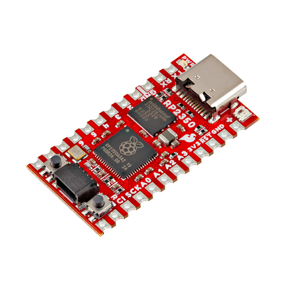
SparkFun Pro Micro - RP2350
SKU: DEV-24870
-
The SparkFun Pro Micro - RP2350 provides a powerful development platform in SparkFun's compact Pro Micro form factor built around the RP2350 from the Raspberry Pi Foundation. This board uses the updated Pro Micro form factor and includes a USB-C connector, Qwiic connector, WS2812B addressable RGB LED, Boot and Reset buttons, resettable PTC fuse as well as PTH and castellated solder pads. This board also includes external memory for the RP2350 with 16MB Flash and 8MB PSRAM both tied to the RP2350's QSPI controller.
The RP2350 is a unique dual-core microcontroller with two ARM® Cortex® M33 processors and two Hazard3 RISC-V processors, all running at up to 150 MHz! Now, this doesn't mean the RP2350 is a quad-core microcontroller. Instead, users can select which two processors to run on boot instead. You can run two processors of the same type or one of each. The RP2350 also features 520kB SRAM in ten banks, a host of peripherals including two UARTs, two SPI and two I2C controllers, and a USB 1.1 controller for host and device support.Purchase from SparkFun
Required Materials
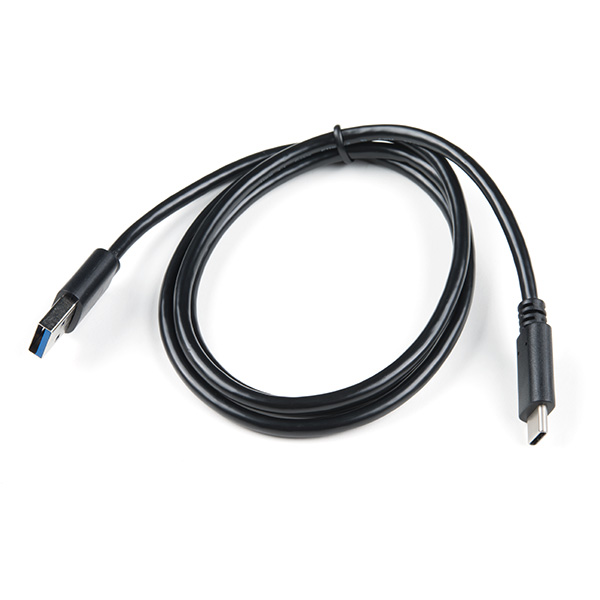
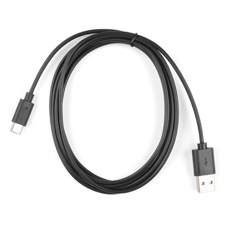
For basic use of the Pro Micro - RP2350 all you'll need is a USB-C cable like the ones listed below:
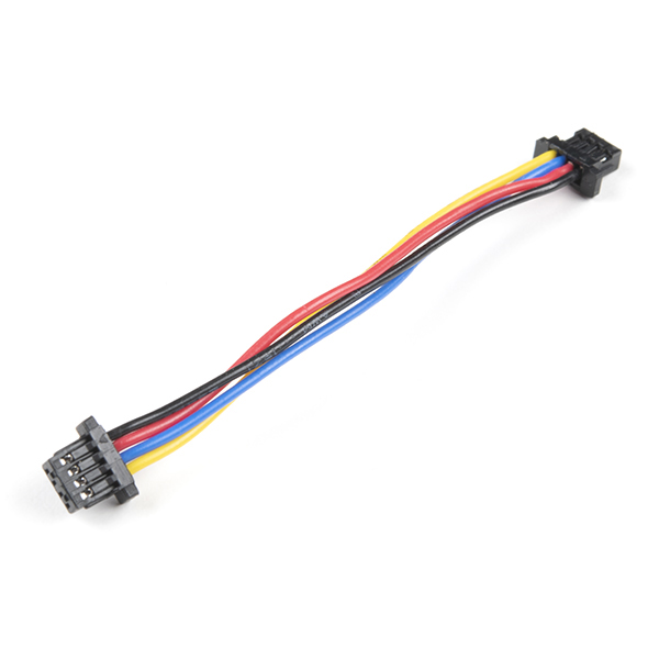
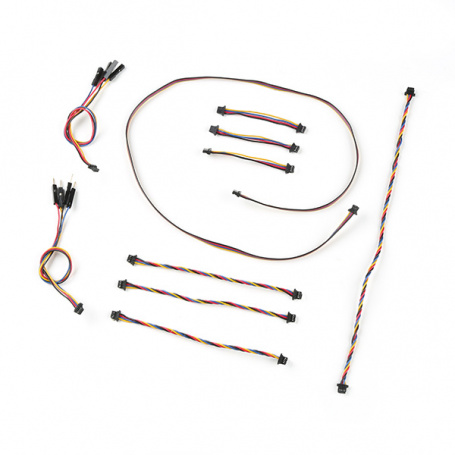
You may also want to get a Qwiic cable or kit to connect the Pro Micro - RP2350 to other Qwiic devices:
Tools
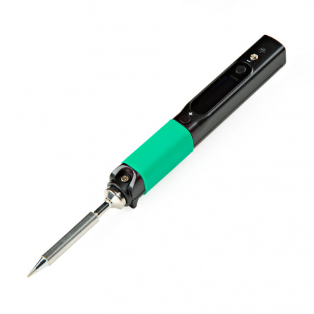
If you prefer a soldered connection or want to modify the solder jumpers on this board, you may need some of the products listed below:
Camera PSRAM Example Materials
This guide includes a detailed example on how to use the PSRAM included on the Pro Micro - RP2350 using a camera connected to the board. If you'd like to follow along with that example, you'll need the following materials. You'll certainly need the camera linked below along with optionaly headers, a breadboard, and jumper wire for prototyping the circuit.
-
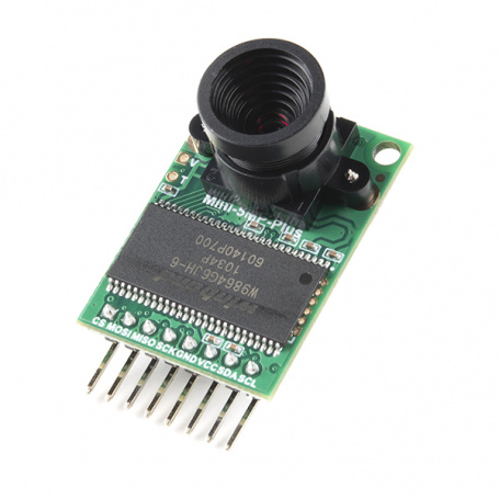
Arducam 5MP Plus OV5642 Mini Camera Module DEV-18440
-
Break Away Headers - Straight PRT-00116
-
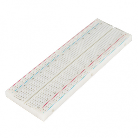
Breadboard - Full-Size (Bare) PRT-12615
-
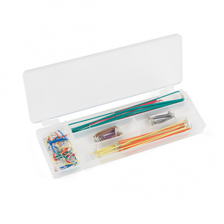
Jumper Wire Kit - 140pcs PRT-00124
Suggested Reading
We designed this board for integration into SparkFun's Qwiic connect system. Click on the banner below to learn more about the SparkFun Qwiic Connect System.

Before getting started with this Hookup Guide, you may want to read through the tutorials below if you are not familiar with the concepts covered in them or want a refresher. If you are using either of the Qwiic Shields linked above, we recommend reading through their respective Hookup Guides before continuing with this tutorial:

Hardware Overview
Let's take a closer look at the RP2350 and other hardware on this Pro Micro.
Raspberry Pi RP2350
The RP2350 from Raspberry Pi packs a whole lot of computing punch in a tiny package. The RP2350 is a unique dual-core microcontroller that has four internal processors (two Arm Cortex-M33 and two Hazard3 RISC-V processors @150 MHz), though you can only select any two of these four to run at the same time.

This internal configuration allows users to customize the chip to their preferred architecture or to use one of each! The RP2350 includes 520kB of on-chip SRAM in ten independent banks and 8kB of one-time-programmable (OTP) storage. It also has an impressive set of security features including optional boot signing with protected OTP storage for the boot decryption key, global bus filtering (based on either Arm or RISC-V security and privilege levels) and more. For a complete overview of the RP2350, refer to the datasheet.
The Pro Micro - RP2350 uses the "A" version of the microcontroller which has 30 3.3V-tolerant GPIO with 4 analog inputs and also includes the following peripheral options:
- 2x UART
- 2x SPI
- 2x I2C
- 24 PWM
- USB 1.1 Controller
- 12 PIO State Machines
- 1x High-Speed Transmit (HSTX) Peripheral for DVI/DSI support (not available on Pro Micro)
Pro Micro Footprint Constraints
Due to size constraints on the Pro Micro footprint, only 18 GPIO are broken out, including all four analog inputs. Unfortunately, this means HSTX is not supported on the Pro Micro - RP2350.
The RP2350 uses five separate power supplies though this board (and most applications) combines several of them into a single regulated 3.3V supply voltage provided either over the USB-C connector or to the RAW pin. If using the RAW pin, max input voltage is 5.3V as RAW connects directly to the WS2812 LED.
Memory
W25Q128 Flash
The W25Q128 Flash IC adds 16MB of extra programming space on the Pro Micro. This connects to the RP2350 over QSPI.

PSRAM
The Pro Micro also includes an 8MB PSRAM IC for dynamic storage. This also connects to the RP2350 over QSPI. PSRAM support is included in the SparkFun MicroPython "early release" firmware found later in this guide and on the product page, but is not natively supported in the Pico SDK as of release. Refer to the Arducam Demo section of this guide for information on how to enable and set up PSRAM using the Pico SDK.

For a complete overview of the PSRAM IC, refer to the datasheet.
Connectors & Pinout
USB-C Connector
The USB-C connector on the board acts as the primary power and programming interface. It also has surface mount solder pads on the bottom of the board for connections to the USB data lines and USB voltage. The USB-C voltage is regulated down to 3.3V which powers all components on the board. The board also has a RAW PTH pin to provide a dedicated supply voltage. If using this pin, the maximum voltage allowed is 5.3V as RAW connects directly to the WS2812.

Qwiic Connector
The board includes a Qwiic connector connected to GPIO 16 (SCL) and GPIO 17 (SDA) with pull-up resistors to 3.3V.

Pinout
This Pro Micro breaks out a total of 28 pins from the RP2350 including four analog pins, two UART interfaces, SPI, and six GPIO. All I/O pins are 3.3V tolerant.

LEDs
This Pro Micro has two LEDs; a red Power LED tied to the 3.3V line and a a WS2812 RGB LED connected to pin 25 on the RP2350.

The board also has a solder pad on the bottom of the board labeled D0 that users can solder to if they would like to daisy chain more WS2812 LEDs to the one on the board.
Buttons
The board has two push buttons connected to the RP2350's Reset and Boot lines.

Holding down the BOOT button during power-up or reset bypasses Flash boot mode and forces the RP2350 into USB boot mode. The buttons are labeled on the back side of the board. If you are looking at them in the orientation of the image above, the BOOT button is on top and the RESET button is on bottom.
Solder Jumpers
Never modified a jumper before?
Check out our Jumper Pads and PCB Traces tutorial for a quick introduction!
There are two solder jumpers on the Pro Micro labeled PWR and SHLD.

The PWR jumper completes the Power LED circuit and is closed by default. Open it to disable the power LED when trying to minimize the total current draw of the board. The SHLD jumper ties the USB-C connector's shield pin to the Pro Micro's ground plane and is closed by default. Open it to isolate this pin from the board's ground.
Board Dimensions
This board matches the Pro Micro footprint and measures 1.3in x 0.7in (33.02mm x 17.78mm).

Need more measurements?
For more information about the board's dimensions, users can download the Eagle files for the board. These files can be opened in Eagle and additional measurements can be made with the dimensions tool.
Eagle - Free Download!
Eagle is a CAD program for electronics that is free to use for hobbyists and students. However, it does require an account registration to utilize the software.
 Dimensions Tool
This video from Autodesk demonstrates how to utilize the dimensions tool in Eagle, to include additional measurements:
Hardware Assembly
Basic Assembly
Getting started with the Pro Micro - RP2350 is as easy as plugging it in over USB. The board ships with simple code that cycles the WS2812 RGB LED through a rainbow so on initial power up you should see that cycle.

From here, you can quickly get started programming the board with either the Pico SDK or MicroPython. If you'd like to quickly get started with a variety of I2C devices, SparkFun carries a variety of Qwiic boards with MicroPython support such as the Optical Tracking Odometry Sensor as shown in the assembly photo below:

Arducam Demo Assembly
Important!
This is an advanced example that assumes users are familiar with using the Pico SDK to build and run projects. If you have not previously used the Pico SDK we strongly encourage going through Raspberry Pi's tutorials on getting started with it before continuing with this example.
If you'd like to follow along with the Arducam PRSAM Demo in this guide, you'll need to connect the Arducam M5 camera module to the Pro Micro over both SPI and I2C as well as connections for input voltage and ground. We recommend soldering male headers to the Pro Micro as the photo below shows and then plugging it into a breadboard for easy prototyping.


New to soldering?
If you have never soldered before or need a quick refresher, check out our How to Solder: Through-Hole Soldering guide.
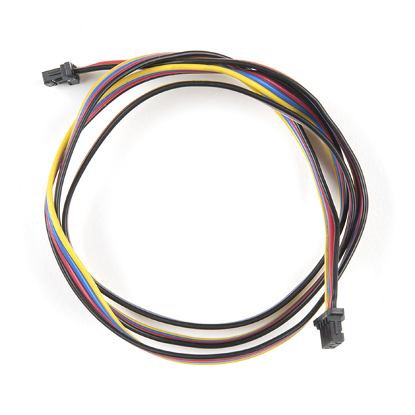
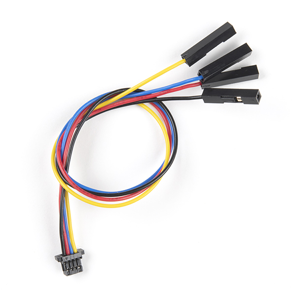
Next, connect the Arducam wire harness to the camera assembly if you have not already then connect it to the Pro Micro - RP2350 following the assembly table below:
| Pro Micro - RP2350 | Arducam Camera |
|---|---|
| 5 | CS |
| 3 | MOSI/COPI |
| 4 | MISO/CIPO |
| 2 | SCK |
| 8 | SDA |
| 9 | SCL |
| 3V3 | VCC |
| GND | GND |
Finally, you'll want to connect a jumper wire between A3 and GND. The code refers to the state of A3/GPIO29 (called 29 in the code) to run the image processing algorithm. The code sets A3/GPIO29 as an input with an internal pull-up resistor enabled. When the pin is pulled LOW through the jumper wire there is no image processing and the image should appear as a normal greyscale. When the jumper is removed, the code enables the processing algorithm to apply image thresholding.
With the wiring completed, it should look similar to the photo below

Software Setup
UF2 Bootloader
The Pro Micro - RP2350 uses a UF2 bootloader for easy flashing/uploading of code to the board. The UF2 bootloader causes the board to show up on your computer as a USB storage device and does not require any drivers for Windows, Mac OSX, and Linux! This bootloader is used for uploading in both the Pico SDK and MicroPython development environments so let's take a brief look at how to enter bootload mode.
What is UF2?
UF2 stands for USB Flashing Format, which was developed by Microsoft for PXT (now known as MakeCode) for flashing microcontrollers over the Mass Storage Class (MSC), just like a removable flash drive. The file format is unique, so unfortunately, you cannot simply drag and drop a compiled binary or hex file onto the board. Instead, the format of the file has extra information to tell the processor where the data goes, in addition to the data itself. For more information about UF2, you can read more from the MakeCode blog, as well as the UF2 file format specification.
Entering the Bootloader
Putting the Pro Micro - RP2350 only requires a couple of presses of the BOOT and RESET buttons. Start by pressing and holding the BOOT button down:

Next, press and release the RESET button while still holding down the BOOT button:

Finally, release the BOOT button and the board should be in bootloader mode and appear on your computer as a USB storage device called "RP2350".
Pico SDK
Raspberry Pi Pico SDK
The Pico C SDK is a C/C++ development kit for Raspberry Pi microcontrollers including the RP2350. Click on the links below for complete documentation on installing and using the SDK.
Pro Micro - RP2350 Board Definition
With the release of Pico SDK v2.1, the Pro Micro - RP2350 is included with it's on board definition. When uploading, select sparkfun_promicro_rp2350.
MicroPython
Setup
MicroPython is an application of the Python 3 language that runs on microcontrollers like the Pro Micro - RP2350 that allows you to easily interact with the board directly over a USB serial interface through either a command line interface or your preferred Python IDE such as Thonny. We'll do a quick overview of how to download MicroPython firmware on to the Pro Micro - RP2350 but for a complete overview of using MicroPython with this and other RP2350 boards, head over to Raspberry Pi's documentation by clicking the button below:
UF2 Firmware
As of this writing, we're waiting on the next release of MicroPython to include UF2 files for the Pro Micro - RP2350 so to get users started before then, we have Beta releases of MicroPython firmware available here or by clicking the button below:
Download the latest release then put the Pro Micro - RP2350 into UF2 bootloader mode and open the location the board appeared as a USB storage device (it should appear as "RP2350"). Next, drag and drop the UF2 file into the RP2350 folder and the board should reboot. Next, open up your preferred MicroPython IDE (or command line interface) and you can start interacting with your Pro Micro. Read on to the MicroPython examples section for a few quick examples to make sure everything is working properly.
CircuitPython
Setup
The Pro Micro - RP2350 is included in the latest release of CircuitPython. If you've never used CircuitPython before, take a read through their tutorial here or click the button below:
Thing Plus - RP2350 Firmware
Download the latest firmware for the Pro Micro - RP2350 from the CircuitPython downloads page and search for "Pro Micro RP2350".
Arduino
Attention
If this is your first time using Arduino, please read through our tutorial on installing the Arduino IDE. If you have not installed an Arduino library before, we recommend you check out our installation guide.
Arduino-Pico Boards
The SparkFun Pro Micro - RP2350 is supported on the Arduino IDE in the Arduino-Pico boards package. To install the package, open the Preferences menu by navigating to File > Preferences. Look at the bottom of the Preferences menu for "Additional boards manager URLS" and then copy this JSON link into that field:
https://github.com/earlephilhower/arduino-pico/releases/download/global/package_rp2040_index.json
Click "OK" to close this menu then navigate to the Boards Manager tool and search for "pico" and download the latest release of "Raspberry Pi Pico" (4.0.1 or later).

For more information on using the Arduino-Pico boards package, check out their documentation page.
Examples
Arducam Demo
Important!
This is an advanced example that assumes users are familiar with using the Pico SDK to build and run projects. If you have not previously used the Pico SDK we strongly encourage going through Raspberry Pi's tutorials on getting started with it before continuing with this example.
The Arducam PSRAM Example is a modified version of Arducam's Videostreaming example that uses the Arducam to take still images and send them to the RP2350 and then process and transmit the images over USB to be displayed using a Processing sketch. The primary goal of this example is to demonstrate how to set up and use PSRAM on the Pro Micro - RP2350 using the Pico SDK and the cool images are a neat bonus!

Software Requirements
Along with the Pico SDK, you'll need to install the following items for this demo to run properly.
Pico SDK Cam Driver
This example uses the Pico SDK, Arducam's Pico Cam driver for the SDK. The example files include the necessary Arducam driver installation but if you'd like to install it separately you can find it in the ArduCAM GitHub repo here.
Processing Software
You'll also need to download and install the Processing software. You can download the program by clicking the button below:
Arducam Demo Files
We've included pretty much everything you'll need to run the example in the Pro Micro - RP2350 GitHub repository here. If you'd like to download a compressed (ZIP) copy of the repository, click the button below:
The C++, .uf2, and cmake.txt files for the example can be found in the "/Examples/Arducam_Demo" folder. Take note of where these are as we'll need them later on.
Uploading and Running Demo
With the Pico SDK set up on your computer, use the following command from the example directory to build the project:
Next, set the Pro Micro in boot mode and upload the .uf2 file to the board.
Processing Sketch
Now that the Pro Micro - RP2350 is running the demo code, open the Processing sketch included in the GitHub repository download. Finally, click the "Run" button in the top left of the Processing window and it should open a new window to display the images the camera is taking. We've done our best to speed up the time between the Arducam capturing an image and displaying it on the computer but it can take a few seconds in between shots. With the camera steady, you should start to see greyscale images like this fancy photo of the ceiling in the SparkFun engineering department:

Now try unplugging the jumper wire between A3 and GND and the next images should be in purely black and white (thresholded) like the screenshot below:

PSRAM Code to Note
Pico SDK PSRAM Support
The Pico SDK may include official PSRAM support for the Pro Micro - RP2350 in the future. This is simply a demo to get users started while that support is being implemented.
The primary goal of this demo is to show how to implement and use PSRAM in your own projects. It's fairly involved and requires overriding the default PSRAM allocations to work with the Pro Micro.
CMakeLists.txt
The CMakeLists.txt file includes the commands to override the default allocation to use a custom allocation created in the "sfe_pico_alloc" folder.
It then adds a subdirectory called "sfe_pico_alloc" to import the custom PSRAM memory allocation for the Pro Micro - RP2350.
add_subdirectory(sfe_pico_alloc)

# pull in common dependencies and additional spi hardware support
target_link_libraries(arducam_demo
    pico_stdlib
    hardware_dma
    hardware_i2c
    hardware_pwm
    ArduCAM
    sfe_pico_alloc
)
C++ PSRAM
The code snippet below shows how to configure and use PSRAM with malloc().
// Create buffer to store image. In this demo, malloc() has been configure to
// use the PSRAM of the SparkFun Pro Micro RP2350, so you don't need to do
// anything else to use the PSRAM!
imageBuf = (uint8_t*) malloc(nRows * nCols);
if (!imageBuf)
{
    // Always good practice to verify that malloc() worked
    printf("Malloc failed! Exiting example\n");
    return 1;
}
MicroPython Examples
Verify MicroPython Firmware & Hardware
First, to make sure everything is running properly, use the sys module to verify the firmware version and machine/board running. Open your preferred interface and enter the following prompts and you should see something similar to the printout below:
import sys
sys.implementation
(name='micropython', version=(1, 24, 0, 'preview'), _machine='SparkFun Pro Micro RP2350 with RP2350', _mpy=7942)
Verify Memory (Internal and PSRAM)
Next, we can verify the total free memory on the Pro Micro which includes the built-in memory on the RP2350 as well as the 8MB PSRAM. We'll use the gc module for this so type in the prompt below and you should see a response close to the value below:
WS2812 LED Control
Finally, we'll make sure we can properly control the WS2812 LED on the Pro Micro using the machine and neopixel classes. The WS2812 Data In pin connects to I/O 25 on the RP2350 so we'll create a pin for it as an OUTPUT and assign it to the LED object. Next, we'll set the color to red and finally write the color values to the LED. The code below goes through all these steps so try copying it on your machine and you should see the WS2812 LED turn red.
import machine, neopixel
pin = machine.Pin(25, machine.Pin.OUT)
led = neopixel.NeoPixel(pin, 1)
led[0] = (255, 0, 0)
led.write()
Try playing around with other values between 0 and 255 for the three colors (R, G, B) and then writing the changes to switch the LED's displayed color.
Troubleshooting
[SparkFun Technical Assistance Page](https://www.sparkfun.com/technical_assistance){ .md-button .md-button--primary }
</center>
<p>If you can't find what you need there, head over to the <a href="https://community.sparkfun.com/">SparkFun Support Forum</a> to create an account, search product forums, and post questions.<p>
Resources:
For more resources related to the SparkFun Pro Micro RP2350, check out the links listed here:
- Product Page
- Schematic (PDF)
- Eagle Files (ZIP)
- Board Dimensions (PDF)
- RP2350 Datasheet (PDF)
- APS6404L PRSAM Datasheet (PDF)
- RP2350 MicroPython Firmware (Beta)
- SparkFun Pico SDK Library
- Arduino Pico Arduino Core
- Raspberry Pi RP2350 Microcontroller Documentation
- Hardware GitHub Respository
- SFE Product Showcase