Introduction
|
The SparkFun 6DoF IMU Breakout - BMI270 (Qwiic) is a Qwiic enabled board based on the ultra-low power BMI270 from Bosch. This chip is a highly integrated, low power IMU designed for wearable, smart clothing and AR/VR applications. Not only does the BMI270 comprise a fast and sensitive accelerometer and gyro pair, but it also contains a number of intelligent, on-chip motion-triggered interrupt features. |
The SparkFun Micro 6DoF IMU Breakout - BMI270 (Qwiic) is the 1x1's mini-me, containing most of it's elder sibling's functionality in a tiny little package. |
Required Materials
To follow along with this tutorial, you will need the following materials. You may not need everything though depending on what you have. Add it to your cart, read through the guide, and adjust the cart as necessary.
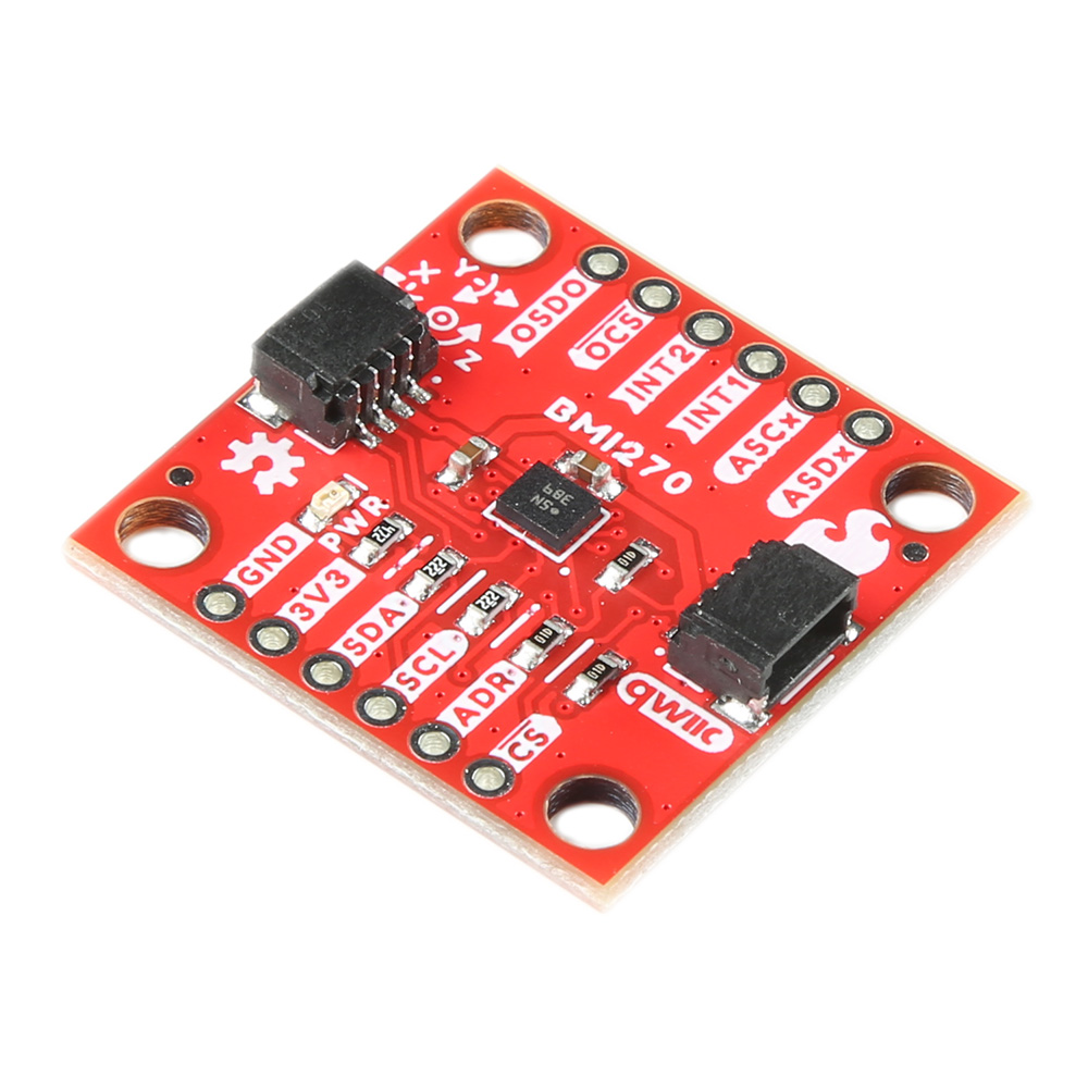 SparkFun 6DoF IMU Breakout - BMI270 (Qwiic)SEN-22397 |
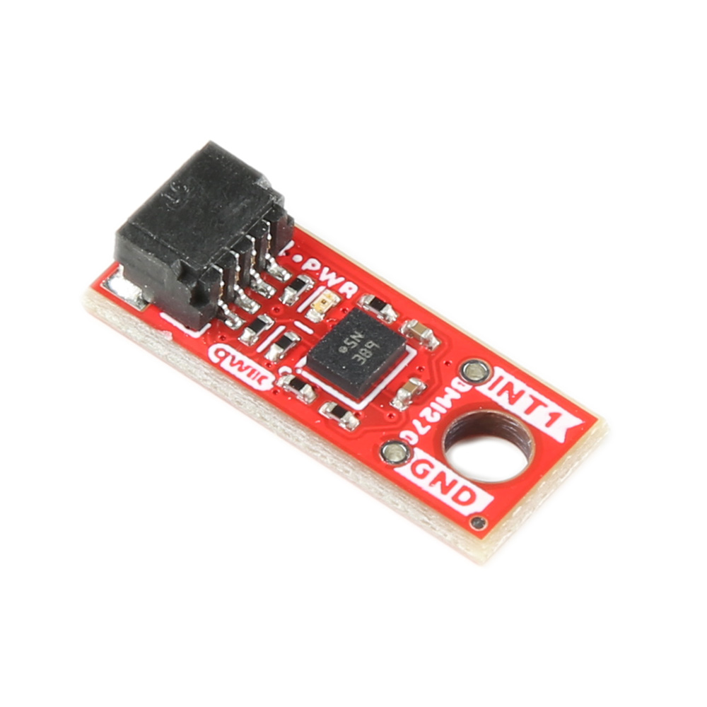 SparkFun Micro 6DoF IMU Breakout - BMI270 (Qwiic)SEN-22398 |
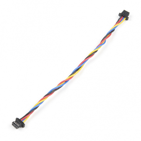 Flexible Qwiic Cable - 100mmPRT-17259 |
USB micro-B Cable - 6 FootCAB-10215 |
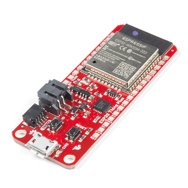
SparkFun ESP32 Thing PlusDEV-15663 |
Suggested Reading
If you aren’t familiar with the following concepts, we recommend checking out these tutorials before continuing.
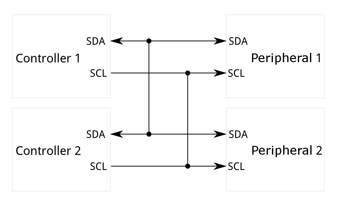

The SparkFun 6DoF IMU Breakout - BMI270 (Qwiic) Sensor takes advantage of the Qwiic connect system. We recommend familiarizing yourself with the Logic Levels and I2C tutorials. Click on the banner above to learn more about Qwiic products.
Hardware Overview
Accelerometer - BMI270
The ultra-low power BMI270 is an IMU optimized for wearables providing precise acceleration, angular rate measurement and intelligent on-chip motion-triggered interrupt features.
The 6-axis sensor combines a 16-bit tri-axial gyroscope and a 16-bit tri-axial accelerometer featuring Bosch’s automotive-proven gyroscope technology. BMI270 includes several functionalities such as an integrated plug-and-play step counter/detector and gesture detection for wrist-worn devices. Moreover, the IMU is suitable for hearables, smart clothes, smart shoes, smart glasses and ankle bands.
|
6DoF BMI270 IC |
Micro 6DoF BMI270 IC |


Qwiic Connector
The Qwiic connector(s) on the SparkFun 6DoF - BMI270 (Qwiic) and SparkFun 6DoF Micro - BMI270 (Qwiic) provide power and I2C connectivity simultaneously.
|
6DoF BMI270 Qwiic Connector |
Micro 6DoF BMI270 Qwiic Connector |


Power
Ideally, power to these boards will be provided by the Qwiic cables. However, should you wish to provide power separately, the 1" x 1" board has its pins broken out to PTH and you can wire up power via these.
Warning
Make sure to pay attention to logic levels - supply voltage range should be between 1.71V - 3.6V.

BMI270 Power Pins
GPIO
This is a quick overview of the pin functionality. For more information, refer to the datasheet.
I2C
If you do not want to use the Qwiic connectors, I2C functionality has been broken out to PTH pins on the 1x1" board.

BMI270 I2C Pins
SPI
Primary SPI functionality has been broken out to the highlighted pins below.

BMI270 SPI Pins
SCL goes to SCK, SDA goes to PICO, ADR goes to POCI, and CS goes to CS
Auxiliary Interface
The ASDx and ASCx pins can be used as a secondary I2C interface where an external sensor like a magnetometer can be connected as a peripheral to the device.

BMI270 Aux I2C Pins
OSCB and OSDO can act as an auxiliary SPI interface where an external controller can be connected to the device. That can include an external OIS control unit. For more information on implementing the OIS interface, see the Datasheet.

BMI270 Aux SPI Pins
Interrupt Pins
Interrupt functionality is available via the INT pins. There are two interrupts available on the 1x1" board, and 1 interrupt available on the Micro. These pins are configurable to be high or low.
|
6DoF BMI270 Interrupt Pins |
Micro 6DoF BMI270 Interrupt Pin |


Jumpers
I2C
Like our other Qwiic boards, the Qwiic 6DoF - BMI270 boards come equipped with pull-up resistors on the clock and data pins. If you are daisy-chaining multiple Qwiic devices, you will want to cut this jumper; if multiple sensors are connected to the bus with the pull-up resistors enabled, the parallel equivalent resistance will create too strong of a pull-up for the bus to operate correctly. As a general rule of thumb, disable all but one pair of pull-up resistors if multiple devices are connected to the bus. To disable the pull up resistors, use an X-acto knife to cut the joint between the two jumper pads highlighted below.
|
6DoF BMI270 I2C Jumper |
Micro 6DoF BMI270 I2C Jumper |


I2C Address
The SparkFun 6DoF - BMI270 (Qwiic) boards have a default I2C address of 0x68, but by cutting the address jumper on the back of the board, you can select 0x69 (GND) or SPI (fully open).
0x68 (default) is actually the GND side, 0x69 is the 3.3V side
|
6DoF BMI270 I2C Address Jumper |
Micro 6DoF BMI270 I2C Address Jumper |


LED
An LED on the front of each board indicates power is being provided to the board. If you don't like LEDs or you are concerned about current draw, cut the jumper highlighted below.
|
6DoF BMI270 LED Jumper |
Micro 6DoF BMI270 LED Jumper |


Board Outline
The SparkFun 6DoF - BMI270 (Qwiic) follows the standard 1" x 1" convention of most of our Qwiic breakout boards.

SparkFun 6DoF - BMI270 (Qwiic)
The SparkFun 6DoF Micro - BMI270 (Qwiic) measures 0.3" x 0.75".

SparkFun 6DoF Micro - BMI270 (Qwiic)
Hardware Assembly
The delightful thing about our Qwiic boards is that they are quite literally plug and play.

SparkFun 6DoF IMU Breakout - BMI270 (Qwiic) Plugged into the ESP32 Thing Plus

SparkFun Micro 6DoF IMU Breakout - BMI270 (Qwiic) Plugged into the ESP32 Thing Plus
Software Setup and Programming
Attention
If this is your first time using Arduino, please review our tutorial on installing the Arduino IDE. If you have not previously installed an Arduino library, please check out our installation guide.
SparkFun has written a library to work with the SparkFun Qwiic 6DoF BMI270 Boards. You can obtain this library through the Arduino Library Manager by searching for "BMI270" and installing the latest version. If you prefer downloading libraries manually, you can grab them from the GitHub Repository.
Attention
Optical Image Stabilization (OIS) has not been implemented in this library. If you wish to use this functionality, please refer to the datasheet.
Arduino Examples
The Arduino Library for the SparkFun 6DoF BMI270 (Qwiic) comes with a slew of examples to get you going. Here we'll just look at a few.
Attention
The BMI270 chip requires an 8kb file to be flashed to memory on the controller. Make sure that whatever controlling board you use, it has enough space.
Example 1: Basic Readings
This first example just does some basic measurements. To find Example 1, go to File > Examples > SparkFun BMI270 Arduino Library > Example01_BasicReadingsI2C:

Finding Example 1
Alternatively, you can expand the link below and copy and paste the code into a shiny new Arduino sketch:
Example 1 Arduino Code
#include <Wire.h>
#include "SparkFun_BMI270_Arduino_Library.h"

// Create a new sensor object
BMI270 imu;

// I2C address selection
uint8_t i2cAddress = BMI2_I2C_PRIM_ADDR; // 0x68
//uint8_t i2cAddress = BMI2_I2C_SEC_ADDR; // 0x69

void setup()
{
    // Start serial
    Serial.begin(115200);
    Serial.println("BMI270 Example 1 - Basic Readings I2C");

    // Initialize the I2C library
    Wire.begin();

    // Check if sensor is connected and initialize
    // Address is optional (defaults to 0x68)
    while(imu.beginI2C(i2cAddress) != BMI2_OK)
    {
        // Not connected, inform user
        Serial.println("Error: BMI270 not connected, check wiring and I2C address!");

        // Wait a bit to see if connection is established
        delay(1000);
    }

    Serial.println("BMI270 connected!");
}

void loop()
{
    // Get measurements from the sensor. This must be called before accessing
    // the sensor data, otherwise it will never update
    imu.getSensorData();

    // Print acceleration data
    Serial.print("Acceleration in g's");
    Serial.print("\t");
    Serial.print("X: ");
    Serial.print(imu.data.accelX, 3);
    Serial.print("\t");
    Serial.print("Y: ");
    Serial.print(imu.data.accelY, 3);
    Serial.print("\t");
    Serial.print("Z: ");
    Serial.print(imu.data.accelZ, 3);

    Serial.print("\t");

    // Print rotation data
    Serial.print("Rotation in deg/sec");
    Serial.print("\t");
    Serial.print("X: ");
    Serial.print(imu.data.gyroX, 3);
    Serial.print("\t");
    Serial.print("Y: ");
    Serial.print(imu.data.gyroY, 3);
    Serial.print("\t");
    Serial.print("Z: ");
    Serial.println(imu.data.gyroZ, 3);

    // Print 50x per second
    delay(20);
}
Make sure you've selected the correct board and port in the Tools menu and then hit the upload button. Once the code has finished uploading, go ahead and open a Serial Monitor. You should see something similar to the following.

Example 1 Output
Example 6: Calibration to NVM
This example does some basic calibration of the BMI270 and then allows you to write those calibrations to non volatile memory. To find Example 6, go to File > Examples > SparkFun BMI270 Arduino Library > Example06_CalibrationNVM.

Finding Example 6
Alternatively, you can expand the link below and copy and paste the code into a shiny new Arduino sketch:
Example 6 Arduino Code
#include <Wire.h>
#include "SparkFun_BMI270_Arduino_Library.h"

// Create a new sensor object
BMI270 imu;

// I2C address selection
uint8_t i2cAddress = BMI2_I2C_PRIM_ADDR; // 0x68
//uint8_t i2cAddress = BMI2_I2C_SEC_ADDR; // 0x69

void setup()
{
    // Start serial
    Serial.begin(115200);
    Serial.println("BMI270 Example 6 - Calibration NVM");

    // Initialize the I2C library
    Wire.begin();

    // Check if sensor is connected and initialize
    // Address is optional (defaults to 0x68)
    while(imu.beginI2C(i2cAddress) != BMI2_OK)
    {
        // Not connected, inform user
        Serial.println("Error: BMI270 not connected, check wiring and I2C address!");

        // Wait a bit to see if connection is established
        delay(1000);
    }

    Serial.println("BMI270 connected!");

    Serial.println("Place the sensor on a flat surface and leave it stationary.");
    Serial.println("Enter any key to begin calibration.");

    // Throw away any previous inputs
    while(Serial.available() != 0) {Serial.read();}
    // Wait for user input
    while(Serial.available() == 0) {}

    Serial.println();
    Serial.println("Average sensor values before calibration:");
    printAverageSensorValues();
    Serial.println();

    // Perform component retrim for the gyroscope. According to the datasheet,
    // the gyroscope has a typical error of 2%, but running the CRT can reduce
    // that error to 0.4%
    Serial.println("Performing component retrimming...");
    imu.performComponentRetrim();

    // Perform offset calibration for both the accelerometer and IMU. This will
    // automatically determine the offset of each axis of each sensor, and
    // that offset will be subtracted from future measurements. Note that the
    // offset resolution is limited for each sensor:
    //
    // Accelerometer offset resolution: 0.0039 g
    // Gyroscope offset resolution: 0.061 deg/sec
    Serial.println("Performing acclerometer offset calibration...");
    imu.performAccelOffsetCalibration(BMI2_GRAVITY_POS_Z);
    Serial.println("Performing gyroscope offset calibration...");
    imu.performGyroOffsetCalibration();

    Serial.println();
    Serial.println("Calibration complete!");
    Serial.println();
    Serial.println("Average sensor values after calibration:");
    printAverageSensorValues();
    Serial.println();

    Serial.println("These calibration values can be stored in the sensor's non-volatile memory (NVM).");
    Serial.println("Would you like to save these values to the NVM? If so, enter 'Y'");

    // Throw away any previous inputs
    while(Serial.available() != 0) {Serial.read();}
    // Wait for user input
    while(Serial.available() == 0) {}

    // Check to see if user wants to save values to NVM
    if(Serial.read() == 'Y')
    {
        Serial.println();
        Serial.println("!!! WARNING !!! WARNING !!! WARNING !!! WARNING !!! WARNING !!!");
        Serial.println();
        Serial.println("The BMI270's NVM only supports 14 write cycles TOTAL!");
        Serial.println("Are you sure you want to save to the NVM? If so, enter 'Y' again");

        // Throw away any previous inputs
        while(Serial.available() != 0) {Serial.read();}
        // Wait for user input
        while(Serial.available() == 0) {}

        // Check to see if user *really* wants to save values to NVM
        if(Serial.read() == 'Y')
        {
            // Save NVM contents
            int8_t err = imu.saveNVM();

            // Check to see if the NVM saved successfully
            if(err == BMI2_OK)
            {
                Serial.println();
                Serial.println("Calibration values have been saved to the NVM!");
            }
            else
            {
                Serial.print("Error saving to NVM, error code: ");
                Serial.println(err);
            }
        }
    }

    Serial.println();
    Serial.println("Example done!");
}

// This helper function samples the sensor several times and prints the average
void printAverageSensorValues()
{
    // Variables to store the sum of each sensor axis
    float accXSum = 0;
    float accYSum = 0;
    float accZSum = 0;

    float gyrXSum = 0;
    float gyrYSum = 0;
    float gyrZSum = 0;

    // Collect 50 measurements at 50Hz
    int numSamples = 50;
    for(int i = 0; i < numSamples; i++)
    {
        // Get measurements from the sensor
        imu.getSensorData();

        // Add this measurement to the running total
        accXSum += imu.data.accelX;
        accYSum += imu.data.accelY;
        accZSum += imu.data.accelZ;

        gyrXSum += imu.data.gyroX;
        gyrYSum += imu.data.gyroY;
        gyrZSum += imu.data.gyroZ;

        // Wait for next measurement
        delay(20);
    }

    // Print acceleration data
    Serial.print("Acceleration in g's");
    Serial.print("\t");
    Serial.print("X: ");
    Serial.print(accXSum / numSamples, 3);
    Serial.print("\t");
    Serial.print("Y: ");
    Serial.print(accYSum / numSamples, 3);
    Serial.print("\t");
    Serial.print("Z: ");
    Serial.print(accZSum / numSamples, 3);

    Serial.print("\t");

    // Print rotation data
    Serial.print("Rotation in deg/sec");
    Serial.print("\t");
    Serial.print("X: ");
    Serial.print(gyrXSum / numSamples, 3);
    Serial.print("\t");
    Serial.print("Y: ");
    Serial.print(gyrYSum / numSamples, 3);
    Serial.print("\t");
    Serial.print("Z: ");
    Serial.println(gyrZSum / numSamples, 3);
}

void loop()
{
    // Nothing to do here
}
Again, make sure you've selected the correct board and port in the Tools menu and then hit the upload button. Once the code has finished uploading, go ahead and open a Serial Monitor. You should see something similar to the following.

Example 6 Output
Warning
This chip only allows a total of 14 writes. Be mindful of this limit when recalibrating.
Example 12: Step Counter
One of the highlights of the BMI270 chip is that it filters out general noise to give you accurate step counts and the like. This example shows the measurements of the BMI270 for walking, running, and when the breakout board is set back down. To find Example 12, go to File > Examples > SparkFun BMI270 Arduino Library > Example12_StepCounter:

Finding Example 12
Alternatively, you can expand the link below and copy and paste the code into a shiny new Arduino sketch:
Example 12 Arduino Code
#include <Wire.h>
#include "SparkFun_BMI270_Arduino_Library.h"

// Create a new sensor object
BMI270 imu;

// I2C address selection
uint8_t i2cAddress = BMI2_I2C_PRIM_ADDR; // 0x68
//uint8_t i2cAddress = BMI2_I2C_SEC_ADDR; // 0x69

// Pin used for interrupt detection
int interruptPin = 5;

// Flag to know when interrupts occur
volatile bool interruptOccurred = false;

void setup()
{
    // Start serial
    Serial.begin(115200);
    Serial.println("BMI270 Example 12 - Step Counter");

    // Initialize the I2C library
    Wire.begin();

    // Check if sensor is connected and initialize
    // Address is optional (defaults to 0x68)
    while(imu.beginI2C(i2cAddress) != BMI2_OK)
    {
        // Not connected, inform user
        Serial.println("Error: BMI270 not connected, check wiring and I2C address!");

        // Wait a bit to see if connection is established
        delay(1000);
    }

    Serial.println("BMI270 connected!");

    // Here we enable the step detector, counter, and activity recognition
    // features of the BMI270; any combination of these is supported.
    //
    // DETECTOR - Triggers an interrupt whenever a step is detected
    // COUNTER  - Increments a counter whenever a step is detected (detector
    //            does not need to be enabled). Triggers an interrupt based on
    //            the step counter watermark (see below)
    // ACTIVITY - The sensor monitors the motion to determine simple user
    //            activities, including standing still, walking, and running. An
    //            interrupt is triggered whenever the activity changes
    imu.enableFeature(BMI2_STEP_DETECTOR);
    imu.enableFeature(BMI2_STEP_COUNTER);
    imu.enableFeature(BMI2_STEP_ACTIVITY);

    // When the step counter feature is enabled, it can trigger an interrupt
    // every number of steps defined by the watermark. This has a factor of 20x,
    // so a value of 1 means 20 step intervals. The step counter interrupt is
    // disabled when the watermark is 0 (default)
    //
    // Note - The step counter and detector interrupts share the same bit in the
    // interrupt status flags registers, so the step detector should be disabled
    // to actually see the step counter interrupts
    imu.setStepCountWatermark(1);

    // The BMI270 has 2 interrupt pins. All interrupt conditions can be mapped
    // to either pin, so we'll just choose the first one for this example
    //
    // Note - The step counter and detector interrupts share the same bit in the
    // interrupt mapping registers, so enabling one enables both
    imu.mapInterruptToPin(BMI2_STEP_COUNTER_INT, BMI2_INT1);
    imu.mapInterruptToPin(BMI2_STEP_ACTIVITY_INT, BMI2_INT1);

    // Here we configure the interrupt pins using a bmi2_int_pin_config, which
    // allows for both pins to be configured simultaneously if needed. Here's a
    // brief description of each value:
    //
    // .pin_type  - Which pin(s) is being configured (INT1, INT2, or BOTH)
    // .int_latch - Latched or pulsed signal (applies to both pins)
    // .pin_cfg   - Array of settings for each pin (index 0/1 for INT1/2):
    //     .lvl       - Active high or low
    //     .od        - Push/pull or open drain output
    //     .output_en - Whether to enable outputs from this pin
    //     .input_en  - Whether to enable inputs to this pin (see datasheet)
    //
    // In this case, we set INT1 to pulsed, active high, push/pull
    bmi2_int_pin_config intPinConfig;
    intPinConfig.pin_type = BMI2_INT1;
    intPinConfig.int_latch = BMI2_INT_NON_LATCH;
    intPinConfig.pin_cfg[0].lvl = BMI2_INT_ACTIVE_HIGH;
    intPinConfig.pin_cfg[0].od = BMI2_INT_PUSH_PULL;
    intPinConfig.pin_cfg[0].output_en = BMI2_INT_OUTPUT_ENABLE;
    intPinConfig.pin_cfg[0].input_en = BMI2_INT_INPUT_DISABLE;
    imu.setInterruptPinConfig(intPinConfig);

    // Setup interrupt handler
    attachInterrupt(digitalPinToInterrupt(interruptPin), myInterruptHandler, RISING);
}

void loop()
{
    // Wait for interrupt to occur
    if(interruptOccurred)
    {
        // Reset flag for next interrupt
        interruptOccurred = false;

        Serial.print("Interrupt occurred!");
        Serial.print("\t");

        // Get the interrupt status to know which condition triggered
        uint16_t interruptStatus = 0;
        imu.getInterruptStatus(&interruptStatus);

        // Check if this is the correct interrupt condition
        if(interruptStatus & BMI270_STEP_CNT_STATUS_MASK)
        {
            Serial.print("Step detected! Total step count: ");

            // Get the step count
            uint32_t count = 0;
            imu.getStepCount(&count);

            // Print step count
            Serial.print(count);
            Serial.print("\t");
        }
        if(interruptStatus & BMI270_STEP_ACT_STATUS_MASK)
        {
            Serial.print("Step activity changed! New activity: ");

            // Get the step activity
            uint8_t activity = 0;
            imu.getStepActivity(&activity);

            // Print step activity
            switch(activity)
            {
                case BMI2_STEP_ACTIVITY_STILL:
                {
                    Serial.print("Still, resetting step counter");
                    imu.resetStepCount();
                    break;
                }
                case BMI2_STEP_ACTIVITY_WALKING:
                {
                    Serial.print("Walking");
                    break;
                }
                case BMI2_STEP_ACTIVITY_RUNNING:
                {
                    Serial.print("Running");
                    break;
                }
                default:
                {
                    Serial.print("Unknown!");
                    break;
                }
            }
        }
        if(!(interruptStatus & (BMI270_STEP_CNT_STATUS_MASK | BMI270_STEP_ACT_STATUS_MASK)))
        {
            Serial.print("Unkown interrupt condition!");
        }

        Serial.println();
    }
}

void myInterruptHandler()
{
    interruptOccurred = true;
}
The wiring for this example is fairly simple. Use the Qwiic connector as normal, and then you'll need to connect your INT1 pin to pin 5/SCK on the ESP32 Thing Plus. Here's what it looks like:

Example 12
Once you get the correct port and board selected and the code is uploaded, you should see something like the following:

Example 12 Output
Troubleshooting
Note
Not working as expected and need help?
If you need technical assistance and more information on a product that is not working as you expected, we recommend heading on over to the SparkFun Technical Assistance page for some initial troubleshooting.
If you don't find what you need there, the SparkFun Forums are a great place to find and ask for help. If this is your first visit, you'll need to create a Forum Account to search product forums and post questions.