Introduction
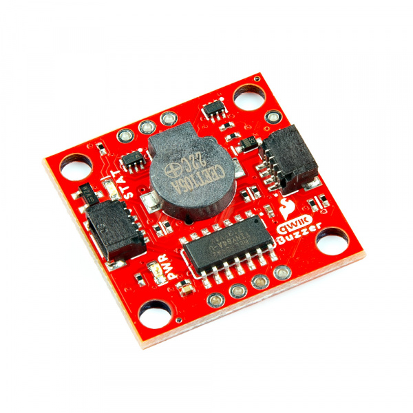
Beep-boop! The SparkFun Qwiic Buzzer adds simple beeps and buzzes to your projects via I2C! Make some noises to alert you when something interesting (or terrible) happens. Simply connect a Qwiic cable and load up some pre-written code to an Arduino to start making noises! For those that want a simple buzz without an Arduino, you can also make noise by simply grounding the trigger pin!
In this tutorial, we'll go over the hardware and how to hookup the breakout board. We will also go over the examples to get started!
Required Materials
To follow along with this tutorial, you will need the following materials. You may not need everything though depending on what you have. Add it to your cart, read through the guide, and adjust the cart as necessary.
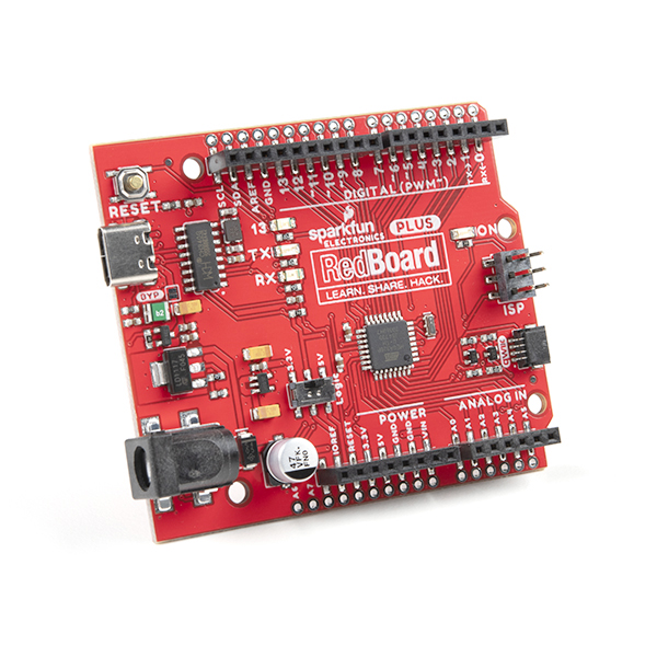
- 1x SparkFun RedBoard Plus [DEV-18158]
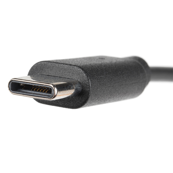
- 1x Reversible USB A to C Cable - 0.8m [CAB-15425]
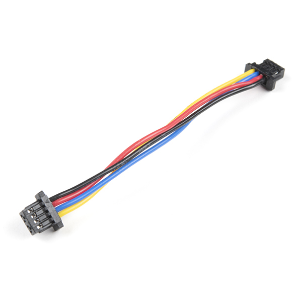
- 1x Qwiic Cable
- Flexible Qwiic Cable - 50mm [PRT-17260], for short distances
- Flexible Qwiic Cable - 500mm [PRT-17257], for those that need to wire the board farther away from your microcontroller
- SparkFun Qwiic Buzzer [BOB-24474]
Tools (Optional)
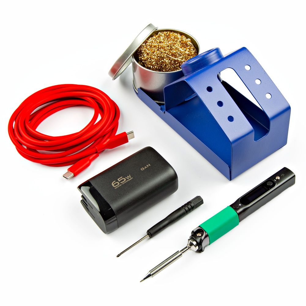
You will need a soldering iron, solder, and general soldering accessories for a secure connection when using the plated through holes.
Prototyping Accessories (Optional)
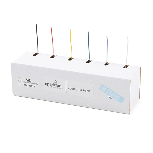
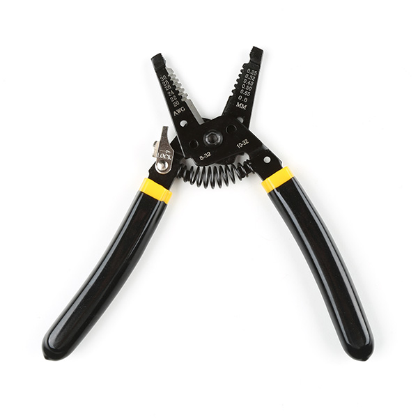
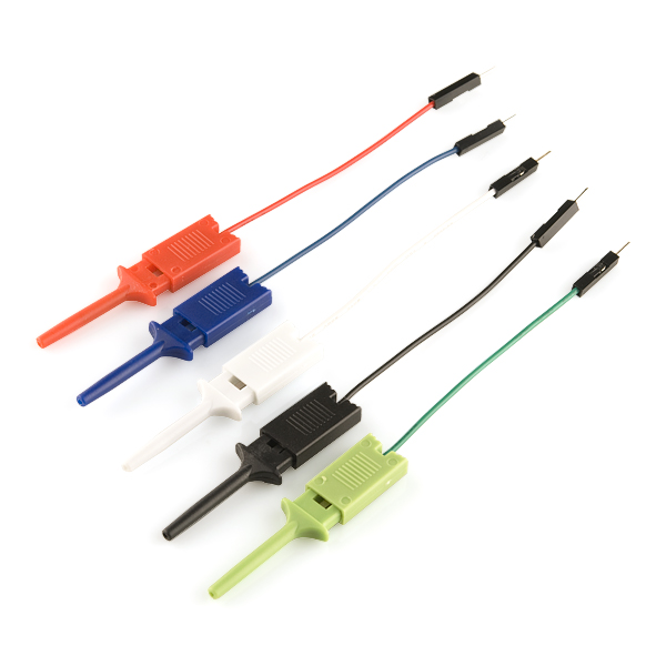
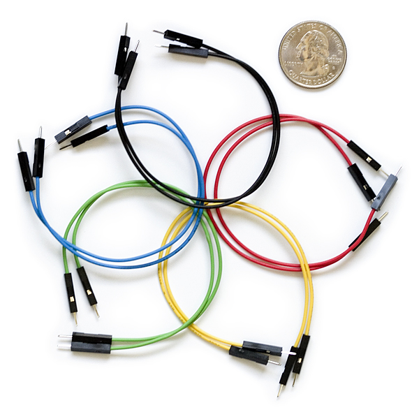
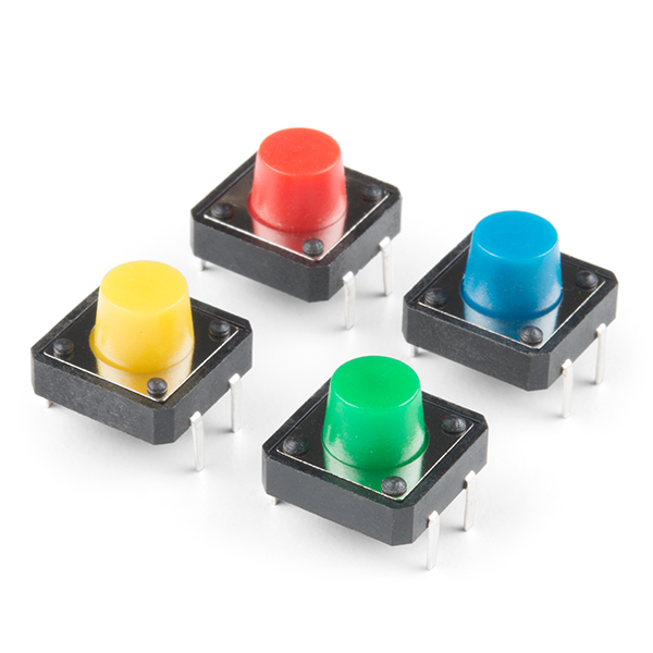
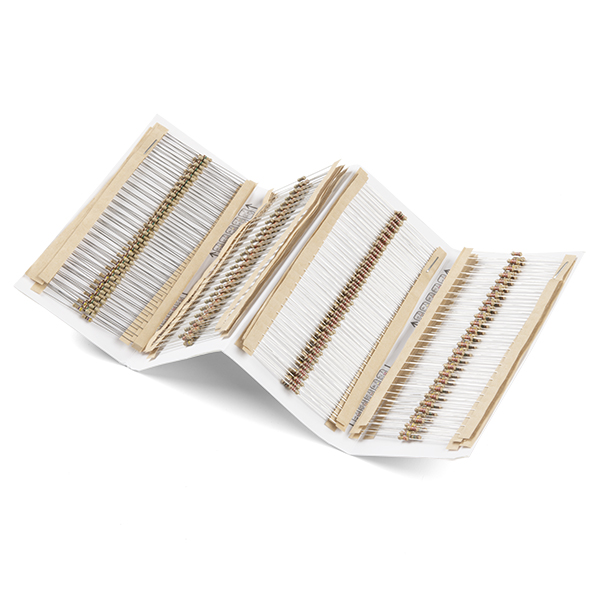
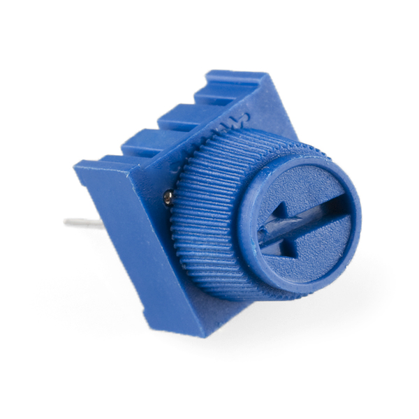
For those connecting to the PTHs on the edge of the board or adding a custom resistor, you will need the following parts. You could use IC hooks for a temporary connection depending on your setup and what you have available. Of course, you will want to the solder header pins for a secure connection. Below are a few prototyping accessories that you may want to consider.
Suggested Reading
If you aren't familiar with the Qwiic Connection System, we recommend reading here for an overview.
If you aren’t familiar with the following concepts, we also recommend checking out a few of these tutorials before continuing.
Hardware Overview
In this section, we will highlight the hardware and pins that are broken out on the SparkFun Qwiic Buzzer.
Power
There are a few power-related nets broken out to Qwiic connectors and through hole pads. The recommended input voltage is 3.3V. The logic levels for the Qwiic Buzzer is 3.3V.
- 3V3 — This connects to the 3.3V net. This net should only be provided with a clean 3.3V power signal. This is also connected to the Qwiic connectors.
- GND — Of course, is the common, ground voltage (0V reference) for the system.
Note
While the ATtiny84 microcontroller can handle a voltage between 1.1V to 5.5V, we recommend only using 3.3V due to the fact that the Qwiic port's I2C data lines use are typically interfacing with a 3.3V system.
Buzzer
Note
Interested in the difference between a magnetic and piezo buzzer? Check out the article from CUI Devices: "Buzzer Basics - Technologies, Tones, and Drive Circuits".
The board would not be the Qwiic Buzzer without... a buzzer! The buzzer uses a small magnetic coil to vibrate a metal disc inside the plastic housing. By pulsating current through the coil at different rates, we can produce different frequencies (pitches) of sound.
Power and control is applied to the buzzer with a set of BJTs. At full volume, it allows the full current of about ~95mA, which makes it really loud. Typically, power and control is directly connected to microcontrollers GPIO, which limits the current to ~40mA. A flyback diode is included to discharge any energy remaining when the buzzer is shut off.
ATtiny84
The brains of the Qwiic Buzzer users an ATtiny84. This IC comes pre-programmed with custom firmware designed to interact with the Arduino Library. The ATtiny84 accepts I2C reads and writes, interprets them, and creates sound by sending a PWM signal to the buzzer. The volume of the buzzer is typically controlled using a variable resistor like a potentiometer. However, four GPIOs, NPN transistors, and resistors are used to provide 7 levels of loudness.
Where's SPI?!?
This board was designed to control the buzzer via I2C. While you can access the SPI pins with the help of the Eagle schematic and board files (e.g. TRIG = POCI, SDA = PICO, and SCL = SCK), these pins are only used for advanced users and programing the AVR microcontroller using custom firmware. For more information about programming an ATtiny84, check out our Tiny AVR Programmer Hookup Guide.
Qwiic and I2C
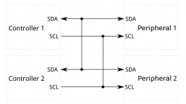
There are two PTHs labeled SDA and SCL on one side of the board. These indicate the I2C data and clock lines and are connected to two 2.2kΩ pull-up resistors. We also conveniently added a GND and 3.3V pin on one side should you decide to daisy chain additional I2C devices to the PTH. Similarly, you can use either of the Qwiic connectors to provide power and send data through I2C. The Qwiic ecosystem is made for fast prototyping by removing the need for soldering. All you need to do is plug a Qwiic cable into the Qwiic connector and voila!
- SCL — I2C clock
- SDA — I2C data
The default I2C address for the Qwiic buzzer is 0x34. This can also be software configured.
Broken Out Pins
- TRIG — The trigger pin enables users to active the buzzer without an I2C whenever the pin is pulled low. This pin also has an alternative function. Pulling the trigger pin low as the board is initially powered up will factory reset the board.
- RST — The reset pin resets the ATTiny84 when the pin is pulled low.
User Resistor
There is a footprint available for a PTH resistor. This is labeled as USER. For users interested in including a custom resistor to control the loudness of the buzzer, you can solder a PTH resistor to the two PTHs. Note that you would need to cut the jumper on the back of the board (labeled as JP1) if you are not using the onboard 2.2kΩ SMD resistor.
LEDs
The board includes the following status LEDs as indicated in the image below.
- PWR — The power LED lights up when the board is powered. This LED is connected the 3.3V net. This LED can be disabled with the PWR jumper on the bottom of the board.
- STAT — The status LED lights up whenever the buzzer is active. This adds a nice visual indicator whenever there is noise.
Jumpers
Note
If this is your first time working with jumpers, check out the How to Work with Jumper Pads and PCB Traces tutorial for more information.
If you flip the board over, you will notice a few jumper pads.
- PWR_LED — The power LED will illuminate when 3.3V is available either over the Qwiic bus or the 3V3 pin. By default, this jumper is closed. Cut this jumper to disable the LED.
- STAT — The status LED will illuminate whenever the buzzer is making noise. By default, this jumper is closed. Cut this jumper to disable the LED.
- I2C — This three way jumper labeled I2C is connected to two pull-up resistors on the I2C data and clock lines. For users that have multiple Qwiic-enabled devices with pull-up resistors enabled, the parallel equivalent resistance will create too strong of a pull-up for the bus to operate correctly. As a general rule of thumb, disable all but one pair of pull-up resistors if multiple devices are connected to the bus.
- JP1 — This jumper pad is available for users that want include a custom resistor to control the loudness of the buzzer. Cut this jumper to disconnect resistor R15. You will need to have a resistor populated for the USER PTH resistor.
Board Dimensions
The board uses the standard 1.0" x 1.0" (25.4mm x 25.4mm) Qwiic board. There are 4x mounting holes by each corner of the board.
Hardware Hookup
In this section, we'll go over how to connect the Qwiic Buzzer to an Arduino microcontroller.
Connecting to the Qwiic I2C Port
Insert a Qwiic cable between the Qwiic Buzzer and your Arduino microcontroller. Then connect a USB cable between the Arduino microcontroller and your computer's COM port. In this case, we used the RedBoard Plus with ATmega328P.
With the Qwiic Buzzer, you can daisy chain more than one buzzer! Typically on an Arduino, you could only use the tone() function with one buzzer at a time and the function could also interfere with other PWM output pins as well. Controlling the Qwiic Buzzer through I2C allows you to play multiple buzzers simultaneously. Just make sure to configure the address of the buzzer and make another instance of any additional buzzer in the code should you decide to control each buzzer separately.
Note
When daisy chaining both boards, you can control both simultaneously when using the same address.
Connecting via PTH
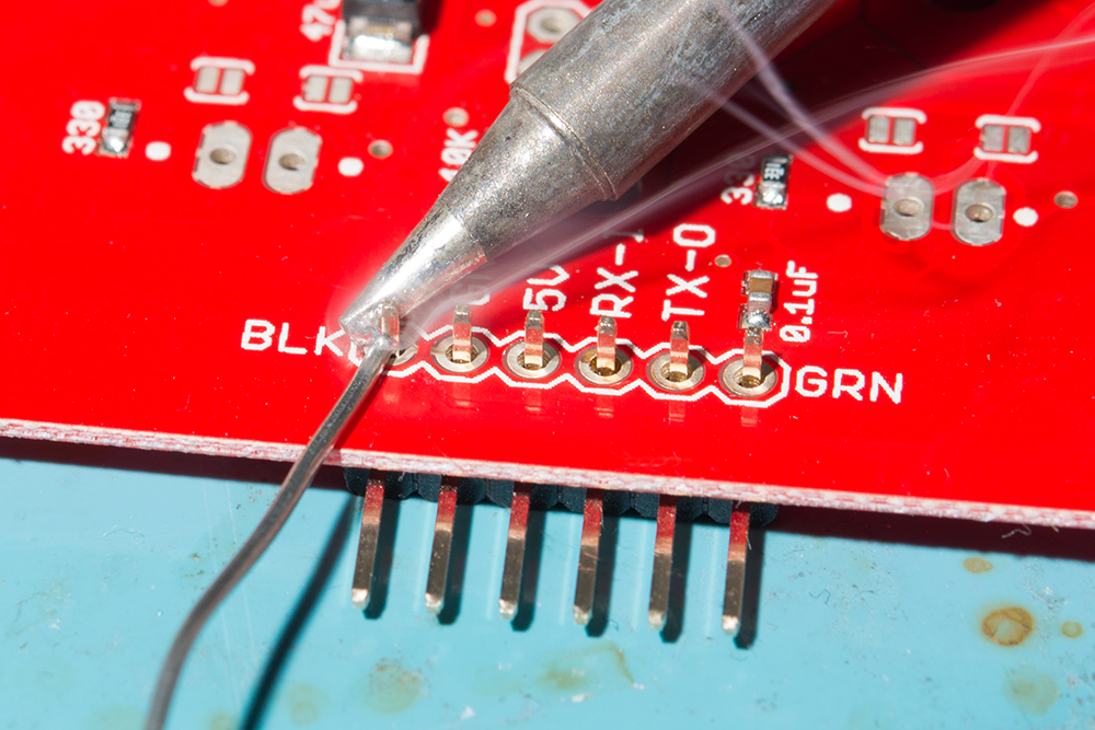
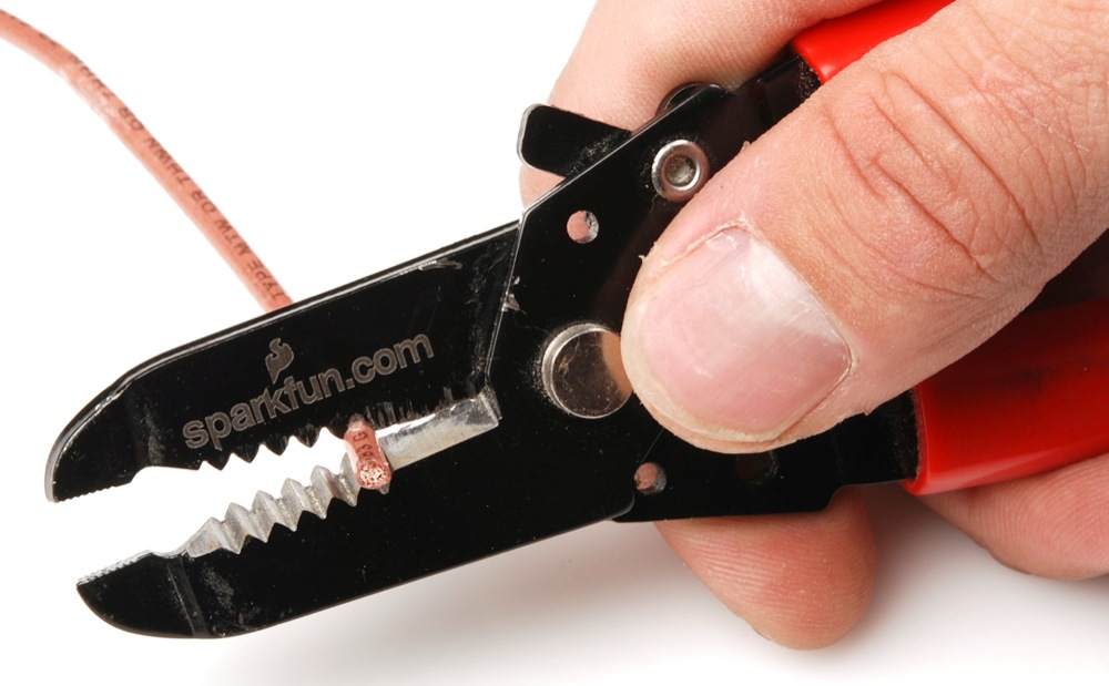
For temporary connections to the PTHs on the edge of the board, you could use IC hooks to test out the pins. However, you'll need to solder headers or wires of your choice to the board for a secure connection. You can choose between a combination of header pins and jumper wires, or stripping wire and soldering the wire directly to the board.
For the custom resistor, you will need to bend the resistor's terminals and insert it into the PTHs where it says USER. You can solder the terminals from the bottom or top. Depending on the size of the resistor, the resistor may not sit flush against the board. You may need to bend the terminals in and push the resistor to the side. The image shown below on the left shows a 1/4 watt resistor with thick leads not sitting flush against the footprint. For those inserting the resistor from the bottom, make sure to have enough room to cut the jumper labeled as JP1 before soldering the resistor's terminals. Of course, make sure to cut off the excess terminals after soldering the resistor and carefully clean the board.
Warning
When cleaning the board, make sure that the buzzer is not submerged under water.
You can also carefully pull the two inner pins out of a 1x4 standard male header pin using pliers, solder the remaining two into the board, and insert the Qwiic Buzzerinto a breadboard. This is useful for those interested in using a 10kΩ potentiometer to control the volume.
Note
By sacrificing two inner male pins from the 1x4 header, the remaining plastic spacers will help keep the single square pins in place as you solder them to the board.
Stand-Alone Mode
For users that simply need to trigger a beeping noise, all you need to do is power the Qwiic Buzzer and ground the trigger pin! If you have a 3.3V voltage regulator, simply connect 3.3V and ground to the Qwiic Buzzer. Then connect the TRIG pin to GND using either a momentary button or jumper wire.
| SparkFun Buck Regulator Breakout 3.3V (AP63203) Pins |
Button | Qwiic Buzzer Pins |
|---|---|---|
| 3V3 | 3V3 | |
| GND | Common | GND |
| Normally Open (NO) | TRIG |
| SparkFun Buck Regulator Breakout 3.3V (AP63203) Pins |
Button | 10kΩ Trim Pot | Qwiic Buzzer Pins |
|---|---|---|---|
| 3V3 | 3V3 | ||
| GND | Common | GND | |
| Normally Open (NO) | TRIG | ||
| Pin 2 (i.e. Center Pin) |
USER PTH 1 (The PTH closest to the Buzzer) |
||
| Pin 1 or 3 | USER PTH 2 (The PTH closest to the Qwiic Connector) |
Installing the Arduino Library
Arduino
This example assumes you are using the latest version of the Arduino IDE on your desktop. If this is your first time using the Arduino IDE, library, or board add-on, please review the following tutorials.
Note
If you've never connected an CH340 device to your computer before, you may need to install drivers for the USB-to-serial converter. Check out our section on "How to Install CH340 Drivers" for help with the installation.
SparkFun has written a library to work with the Qwiic Buzzer. You can obtain this library through the Arduino Library Manager by searching for "SparkFun Qwiic Buzzer". Find the one written by SparkFun Electronics and install the latest version. Users who prefer to manually install the library can get it from the GitHub Repository or download the .ZIP by clicking the button below:
Arduino Examples
--8<-- "./docs/arduino_examples.md
Troubleshooting
General Troubleshooting Help
Note
Not working as expected and need help?
If you need technical assistance and more information on a product that is not working as you expected, we recommend heading on over to the SparkFun Technical Assistance page for some initial troubleshooting.
If you don't find what you need there, the SparkFun Forums are a great place to find and ask for help. If this is your first visit, you'll need to create a Forum Account to search product forums and post questions.
Resources
Now that you've successfully got your SparkFun Qwiic Buzzer up and running, it's time to incorporate it into your own project! This board is great for adding a simple audible sound to your projects. Pair board with the Qwiic RTC to make an alarm clock, play a tune with the Qwiic RFID, or add a sound effect to your robot. So what are you waiting for?!? Start making some noise in your projects with the SparkFun Qwiic Buzzer! For more information, check out the resources below:
- Schematic (PDF)
- Eagle Files (ZIP)
- Board Dimensions (PNG)
- Datasheet
- Qwiic Info Page
- Arduino Library
- ReadtheDocs: Qwiic Buzzer
- Qwiic Buzzer Python Package
- GitHub Hardware Repo
Or check out this blog post for ideas.
