Introduction
-
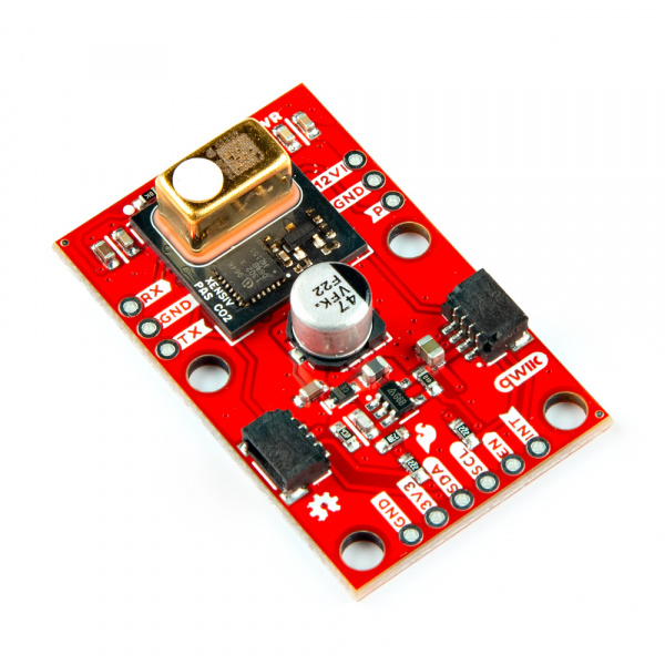
The SparkFun Photoacoustic Spectroscopy CO2 Sensor - PASCO2V01 (Qwiic) is a breakout using the XENSIV™ PAS CO2 sensor package from Infineon© which measures highly-accurate CO2 concentrations and outputs data in direct parts-per-million (ppm) format over I2C, UART and PWN. The PAS CO2 employs a photoacoustic spectroscopy measurement system that combines narrow-band filtered IR light and a highly sensitive microphone inside the sensing cavity. The PAS CO2 measures CO2 concentrations from 0 to 32,000ppm with a best accuracy of ±(30ppm +3%) when reading between 400 and 5,000ppm. It also includes and integrated microcontroller that processes and converts the data into direct ppm readout over any of the three communication interfaces. This board includes a boost circuit to increase a 3.3V supply from the Qwiic connectors (or external) to 12V for the IR emitter supply voltage. This circuit includes a series of decoupling capacitors to output a clean 12V. We've also broken out all of the pins from the PAS CO2 package to 0.1"-spaced PTH headers so users have full access to all of the sensor's features.
Purchase from SparkFun
In this guide we'll go over the hardware on this Qwiic breakout, how to assemble it into a circuit, and how to install and use Infineon's XENSIV PAS CO2 Arduino Library to configure and interact with the sensor.
Required Materials
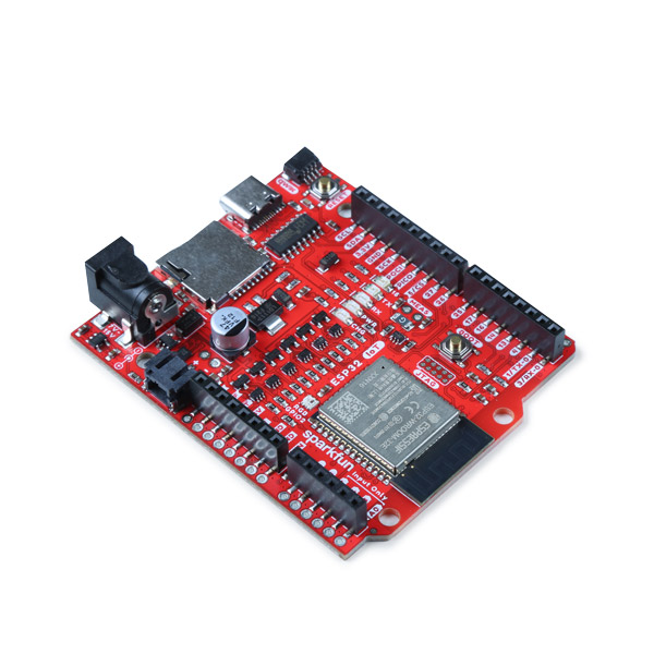
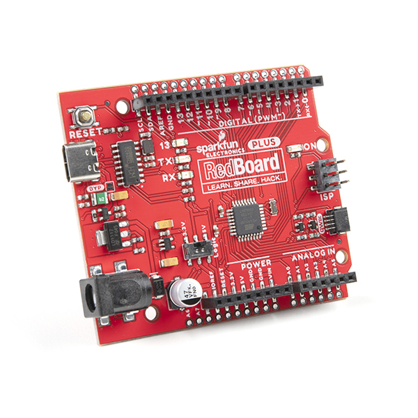
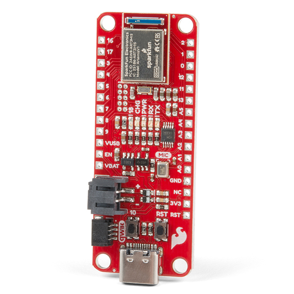
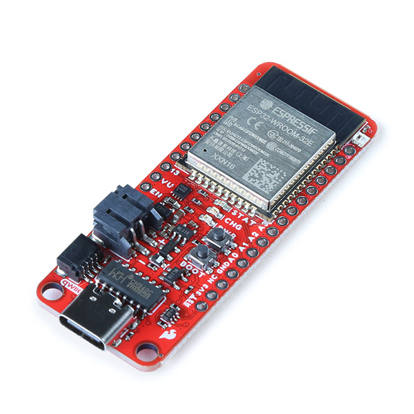
To follow along with this guide you will need a microcontroller to communicate with this breakout. Below are a few options that come Qwiic-enabled out of the box:
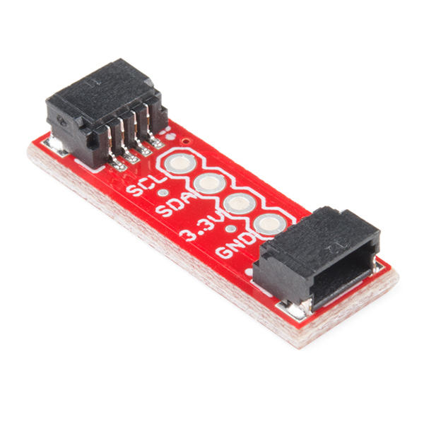
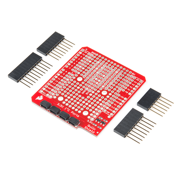
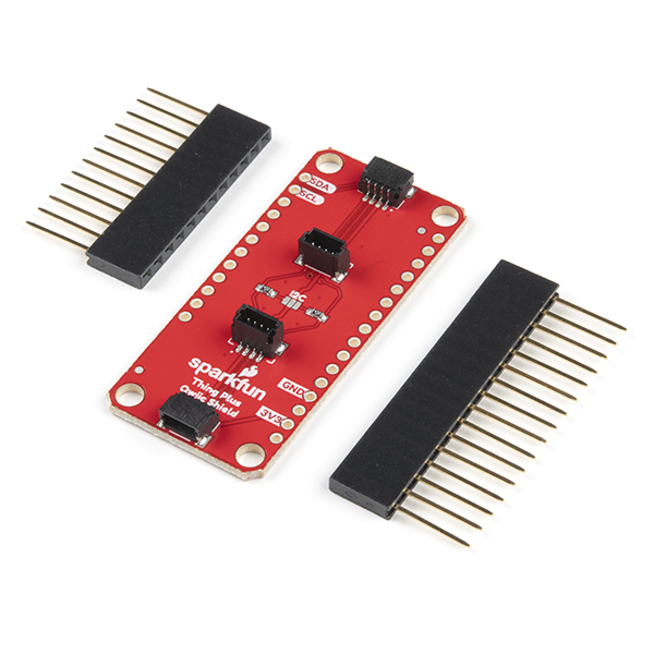
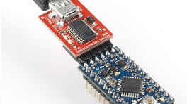
If your chosen microcontroller is not already Qwiic-enabled, you can add that functionality with one or more of the following items:
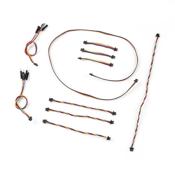
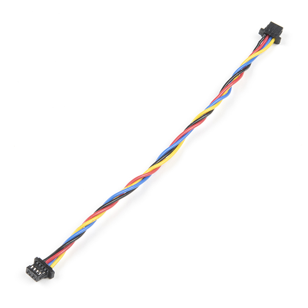
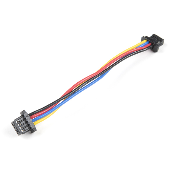
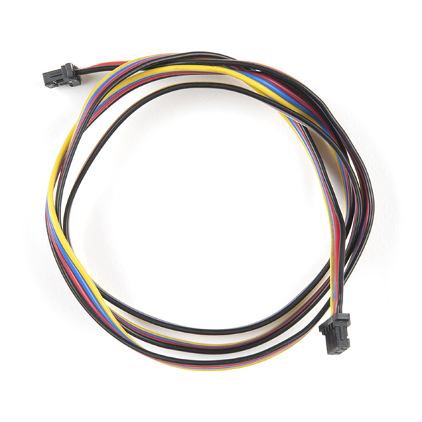
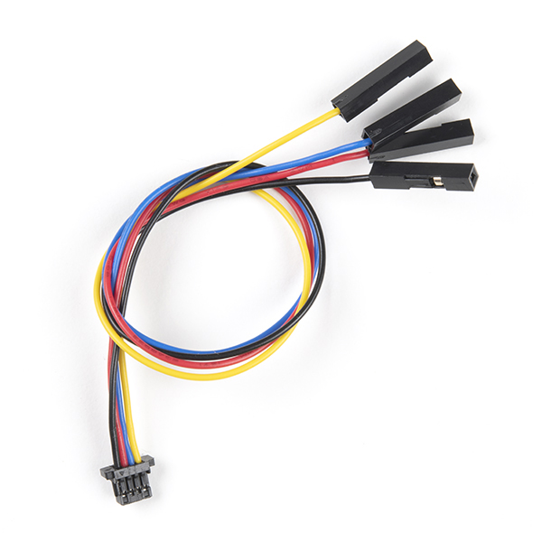
You will also need at least one Qwiic cable to connect your breakout to your microcontroller:
Optional Materials
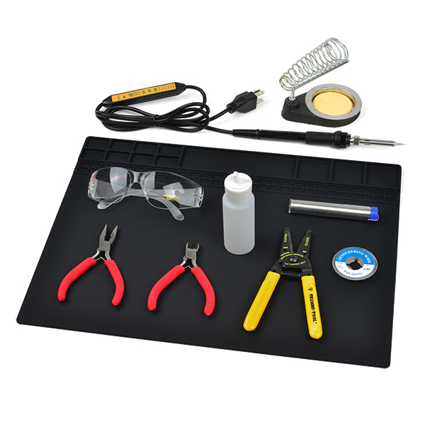
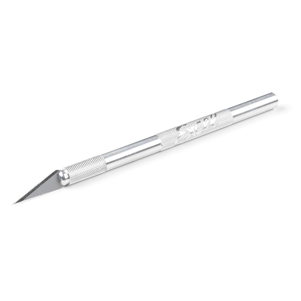
If you prefer a soldered connection for I2C, prefer to use either the UART or PWM interfaces, or want to follow along with the Early Measurments Example later in this guide, you may need some of the products listed below:
Suggested Reading
We designed this board for integration into SparkFun's Qwiic connect system. Click on the banner below to learn more about the SparkFun Qwiic Connect System.

Before getting started with this Hookup Guide, you may want to read through the tutorials below if you are not familiar with the concepts covered in them or want a refresher. If you are using either of the Qwiic Shields linked above, we recommend reading through their respective Hookup Guides before continuing with this tutorial:


Hardware Overview
Let's take a closer look at the XENSIV™ PAS CO2 sensor and other hardware present on this Qwiic breakout.
XENSIV PAS CO2 Sensor
The XENSIV PAS CO2 sensor from Infineon utilizes a photoacoustic spectroscopy gas measurement system to accurately measure CO2 concentration in a very stable sensing environment.

Photoacoustic spectroscopy uses a combination of narrow-band filtered IR light and MEMS microphone to measure CO2 molecule concentration with high accuracy. The PAS CO2 package includes an on-board microcontroller that parses the data recorded and converts it into direct parts per million (ppm) output to either UART, I2C, or pulse width modulation (PWM). For a complete overview of the PAS CO2, refer to the datasheet.
You may be wondering what photoacoustic spectroscopy means. Photoacoustic measuring uses light (photo) and sound/vibrations (acoustic) in tandem to measure the the photoacoustic effect when energy is absorbed by particles. The sensor shines a specific frequency of IR light that CO2 molecules absorb causing them to heat up, expand and release a pressure wave (sound) wave that the MEMS microphone picks up. This data is then processed and output in human-readable concentrations in PPM. This is just a quick and basic explanation of photoacoustic spectroscopy used in the PAS CO2 sensor. For detailed information, refer to Invensense's product brief for the sensor.
The PAS CO2 has three operating modes: Idle, Continuous, and Single-Shot. In idle mode the sensor is inactive and does not take any measurements. In continuous mode the sensor takes periodic measurements and returns to idle once the measurement sequence finishes. The measurement period is configurable from anywhere between 5 to 4095 seconds. In single-shot mode the sensor enters a single measurement period and then returns to idle mode.
| Parameter | Units | Min | Typ | Max | Notes |
|---|---|---|---|---|---|
| CO2 Output Range | ppm | 0 | - | 32,000 | |
| CO2 Measurement Accuracy | ppm | - | ±(30 + 3%) | - | Accuracy when measuring between 400ppm and 5,000ppm. |
| Ambient Temperature Range | °C | 0 | - | 50 | |
| Relative Humidity Range | %RH | 0 | - | 85 | |
| CO2 Sampling Time | s | 5 | 60 | 4095 |
Power & Boost Circuit
The PAS CO2 uses two input voltages, 12V for the IR emitter and 3.3V for the microcontroller and other components. This breakout has a AP3012 boost regulator to step up 3.3V from the Qwiic connectors to 12V along with a series of decoupling capacitors to ensure the IR emitter gets a clean supply voltage. The breakout also has PTH pins for both supply voltage if users prefer to power the sensor from a dedicated power supply. If you select this option, ensure both voltages fall within the supply range for each input (VDD3.3: 3V-3.6V and VDD12: 10.8V-13.2V).
Communication Interfaces & Pinout
We designed this board to set the PAS CO2 to communicate by I2C by default but have included PTH pins for both the UART and PWM interfaces along with solder jumpers to enable/disable all three options.

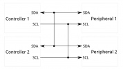
Qwiic/I2C
The board routes the PAS CO2's I2C interface to a pair of Qwiic connectors as well as 0.1"-spaced plated through-hole (PTH) headers. This header also includes the PAS CO2's Interrupt pin, the AP3012 boost regulator's Enable pin, as well as connections to 3.3V and GND. The PAS CO2's unshifted 7-bit I2C address is 0x28.
The Interrupt pin can function as a standard hardware interrupt for alarm thresholds, data ready, and sensor busy statuses but also is configurable to act as an early measurement start notification. In this mode, the interrupt pin enters an active state (set to either active-high or active-low) roughly one second before a measurement period which can be tied to the enable pin for the LM62421 boost regulator. The interrupt turns this power supply on for roughly 0.2s at the start of the measurement period and again at the end. The design of the board has both this pin and the boost regulator's enable pin next to each other so users can tie them to each other to turn on the boost regulator just before measurement occurs to help conserve power.
UART
The board routes the TX and RX pins to one side of the board along with a Ground PTH for voltage reference if needed. This interface is disabled by default and requires adjusting the PSEL jumper on the back of the board. Read on to the Solder Jumpers section for more information about enabling UART.
PWM
The PAS CO2's PWM interface is routed to the oppposite side of the board from the UART and also includes a Ground PTH for voltage reference. This interface is also disabled by default and can be enabled by adjusting the PWM jumper on the back of the board. Read on to the Solder Jumpers section for more information on enabling PWM output.
Power LED
The lone LED on this board labeled PWR indicates when the 3.3V circuit is powered.

Solder Jumpers
The breakout has four solder jumpers labeled PWR, PSEL, PWM, and I2C.

- PWR: The PWR jumper completes the Power LED circuit. Open it to turn off the power LED to reduce the current draw of the board.
- PSEL: The PSEL jumper is a three-way jumper that sets whether the PAS CO2 outputs over I2C (Default) or UART (Alternate). By default, the jumper pulls the PSEL line to Ground and enables the I2C interface indicated by the small "I" on the jumper. Severing the trace between the "I" pad and center pad and then connecting the center pad to the "U" pad switches the PAS CO2 to communicate over UART.
- PWM: The PWM jumper controls the PWM output through the PWM disable input pin. This jumper is OPEN by default to disable PWM through the internal pullup resistor. Close it to tie the PWM disable pin to ground and enable PWM output.
- I2C: Pulls the SDA/SCL lines to 3.3V through a pair of 2.2kΩ resistors. Open the jumper completely to disable pullups on these lines if needed.
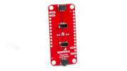
Board Dimensions
This breakout measures in a bit larger than the Qwiic 1"x1" standard to accomidate the boost circuit for the IR emitter. The board measures 1"x1.6"(25.4mm x 40.64mm) with four mounting holes that fit a 4-40 screw.

Hardware Assembly
Now that we're familiar with the PAS CO2 sensor and other hardware on this breakout, it's time to assemble it into a circuit.
Qwiic Assembly
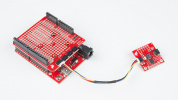
SparkFun's Qwiic system makes assembling a circuit a breeze. Simply plug the breakout into your chosen microcontroller with a Qwiic cable. After assembling your circuit, it should look similar to the photo below:

Soldered Assembly
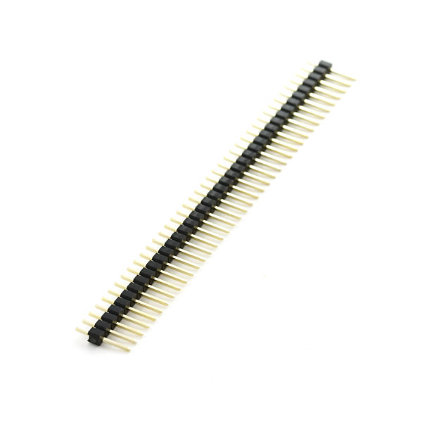
Those who prefer to use either the UART or PWM interfaces or the other pins broken out on this board should solder wires or header pins to the PTH pins on the side of the board. If you're not familiar with through-hole soldering or would like a refresher, take a look at our Through-Hole Soldering Tutorial:

Boost Regulator Interrupt Assembly
The Early Measurement example in the Examples section demonstrates how to use the PAS CO2's Interrupt pin as an early measurement signal to control the boost regulator's power during measurement periods. If you want to follow along with that example you'll need to tie the INT PTH pin and EN PTH pin together. We recommend a set of headers to these PTHs and bridge the EN and INT pins together using a jumper like this. You can also create a temporary connection between these pins with some alligator clips or through some wiring on a breadboard.
Next, connect the INT pin on the PAS CO2 sensor breakout to an interrupt capable pin on your development board. The example assumes the use of an ESP32 development board and sets pin 13 so adjust the wiring and code if necessary. With everything wired up on a breadboard, the circuit should look something similar to the photo below:

Calibration Procedure
The PASCO2V01 sensors require a week long calibration period, measuring every 10 seconds. During that period, the sensor must be outside for at least 30 minutes while taking measurements. Refer to the Automatic baseline offset correction (ABOC) and forced compensation scheme (FCS) application note for complete information about the calibration process. The graph below shows three sensors data outputs merge together during our calibration testing:

Installation Recommendations
For ideal measurements, Infineon has several recommendations for installing the sensor in the final application found in this application note. The list below outlines most of them but for complete information, refer to the app note linked above.
- Allow space above the sensor at least 12mm tall with a minimum opening size of 14mm x 14mm.
- Avoid direct airflow in front of the sensor.
- Isolate the sensor from ambient heat sources.
- Isolate the sensor from vibration sources.
- Avoid placing the sensor in direct sunlight.
- Prevent any condensation/water contact with the sensor.
Software Setup and Programming
Attention
If this is your first time using Arduino, please read through our tutorial on installing the Arduino IDE. If you have not installed an Arduino library before, we recommend you check out our installation guide.
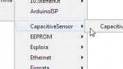
Infineon has written an Arduino Library for the PAS CO2 sensor to make it easy to get CO2 data from the sensor along with other settings and features. Users can download the library through the Arduino Library Manager by searching for "XENSIVE PAS CO2x" as the screenshot below shows:
Those who prefer to manually install it can download a ZIP of the library from the GitHub repository or by clicking the button below:
With the library installed let's move on to looking at a few of the examples included in it.
Example Code
icon: simple/arduino
Example 1 - Continuous Mode
The first example demonstrates how to initialize the sensor over I2C to measure CO2 data in Continuous Mode and print it out over serial. Open the example by navigating to File > Examples > XENSIV PAS CO2 > continuous-mode. After opening the example, select your Board and Port (in our case, SparkFun RedBoard IoT), and click "Upload". Open the serial terminal with the baud set to 9600 and you should see the same as the screenshot below:

Example 2 - Boost Regulator Early Notification
The second example follows the assembly step in the Hardware Assembly section tying the PAS CO2's INT pin to the boost regulator's EN pin to control power for the regulator during measurements. This is a custom example we wrote so you'll need to get it from the GitHub Repository or by copying the code below into a blank sketch:
Early Measurement Example
 /*
  *  Name: Example01_EarlyMeasurementStartInterrupt
  *
  *  By: SparkFun Electronics, based on code from Infineon
  *
  *  SPDX-License-Identifier: MIT
  *
  *
  *  Description:
  *  This example is based on the early notification example from Infineon's
  *  `arduino-pas-co2-sensor` library. The biggest deviation is to make it
  *  specific to the ESP32 Thing Plus C. This example interfaces the interrupt
  *  pin of the ESP32 Thing Plus C for readout synch and ties the INT pin to the
  *  EN pin on the Qwiic PASCO2V01 board.
  *
  *  Please see examples/XENSIV PAS CO2/early-notification for more details.
  *
  *  Feel like supporting open source hardware?
  *  Buy a board from SparkFun!
  *  SparkFun Photoacoustic Spectroscopy CO2 Sensor - PASCO2V01 (Qwiic) (SEN-22956) https://www.sparkfun.com/products/22956
  *  SparkFun IoT RedBoard - ESP32 Development Board (WRL-19177) https://www.sparkfun.com/products/19177
  *
  *  Hardware connections:
  *  Connect the qwiic connector between the ESP32 Thing Plus C and the Qwiic PASCO2V01.
  *  Need a qwiic cable? Get one here: https://www.sparkfun.com/products/17260
  *  Using a breadboard, connect a jumper between the INT and EN pins, then
  *    connect it to pin 12 on the ESP32 Thing Plus C.
  *
  */

 #include <Arduino.h>
 #include <pas-co2-ino.hpp> // http://librarymanager/All#XENSIV_PAS_CO2

 uint8_t intPin = 13; // ESP32 Thing Plus C pin, change for your hardware.

 #define I2C_FREQ_HZ 400000
 #define PERIODIC_MEAS_INTERVAL_IN_SECONDS 10
 #define EARLY_NOTIFICATION_ENABLED true

 PASCO2Ino myCO2Sensor(&Wire, intPin);

 int16_t co2ppm;
 Error_t err;

 /*
  * ISR will be called when the sensor is about start performing a measurement
  * and when it's completed. This will allow the main loop to read the
  * measurement when one is ready.
  */
 volatile bool measurementReady = false;
 void isr (void *) {
   if (digitalRead(intPin) == LOW)
     measurementReady = true;
   else
     measurementReady = false;
 }

 void setup() {
   Serial.begin(115200);

   // Wait for serial to open.
   while(!Serial) {
     delay(100);
   }

   // Start I2C.
   Wire.begin();
   Wire.setClock(I2C_FREQ_HZ);

   // Initialize the sensor.
   err = myCO2Sensor.begin();
   if(XENSIV_PASCO2_OK != err) {
     Serial.print("Initialization error: ");
     Serial.println(err);
   }

   // Start measurement every 10s, no alarm set, pass in the ISR, and enable early notification.
   err = myCO2Sensor.startMeasure(PERIODIC_MEAS_INTERVAL_IN_SECONDS, 0, isr, EARLY_NOTIFICATION_ENABLED);
   if(XENSIV_PASCO2_OK != err){
     Serial.print("Start measurement error: ");
     Serial.println(err);
   }

   Serial.println("Sensor setup complete and measurement started successfully.");

 }

 void loop() {
   if (measurementReady) {

     // Clear flag
     measurementReady = false;

     Serial.println("Measurement ready.");

     err = myCO2Sensor.getCO2(co2ppm);
     if(XENSIV_PASCO2_OK != err){
       Serial.print("CO2 measure error: ");
       Serial.println(err);
     }

     Serial.print("CO2 PPM value: ");
     Serial.println(co2ppm);
   }

 }
Select your board and port and upload the example. After the uploade completes, open the serial terminal with the baud set to 115200 and you should see a printout similar to the one below with CO2 measurements printing every ten seconds:
Troubleshooting Tips
Ideal Installation Recommendations
For ideal measurements, Infineon has several recommendations for installing the sensor in the final application found in this application note. The list below outlines most of them but for complete information, refer to the app note linked above.
- Allow a space above the sensor at least 12mm tall with a minimum opening size of 14mm x 14mm.
- Avoid direct airflow in front of the sensor.
- Isolate the sensor from ambient heat sources.
- Isolate the sensor from vibration sources.
- Avoid placing the sensor in direct sunlight.
- Prevent any condensation/water contact with the sensor.
Calibration Procedure
The PASCO2V01 sensors require a week long calibration period, measuring every 10 seconds. During that period, the sensor must be outside for at least 30 minutes while taking measurements. Refer to the Automatic baseline offset correction (ABOC) and forced compensation scheme (FCS) application note for complete information about the calibration process. The graph below shows three sensors data outputs merge together during our calibration testing:
General Troubleshooting
Need Help?
If you need technical assistance or more information on a product that is not working as you expected, we recommend heading on over to the SparkFun Technical Assistance page for some initial troubleshooting.
If you can't find what you need there, the SparkFun Forums is a great place to search product forums and ask questions.
Account Registration Required
If this is your first visit to our forum, you'll need to create a Forum Account to post questions.