Quick Start Guide
In this Quick Start guide we'll go over how to assemble the SparkFun Qwiic 12 Bit DAC Breakout - MCP4725 in a Qwiic circuit with the RedBoard IoT - RP2350 and connect the analog output signal to an LED to visualize the output signal fluctuating in a triangle waveform.
This guide assumes users have a basic understanding of using Qwiic breakout and development boards, through-hole soldering, breadboard prototyping as well as how to use the Arduino IDE. If you're not familiar with all of these concepts, read on through the rest of this Hookup Guide for detailed information on how to use this breakout board with the Arduino IDE.
Demo Circuit Assembly
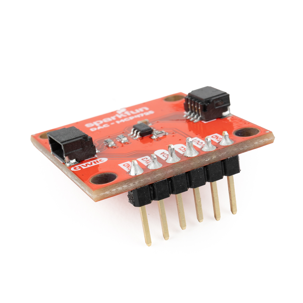
Since we're using this board for prototyping, we soldered male headers to the Qwiic DAC Breakout's PTH pads to plug it into a breadboard and connect it to the LED:
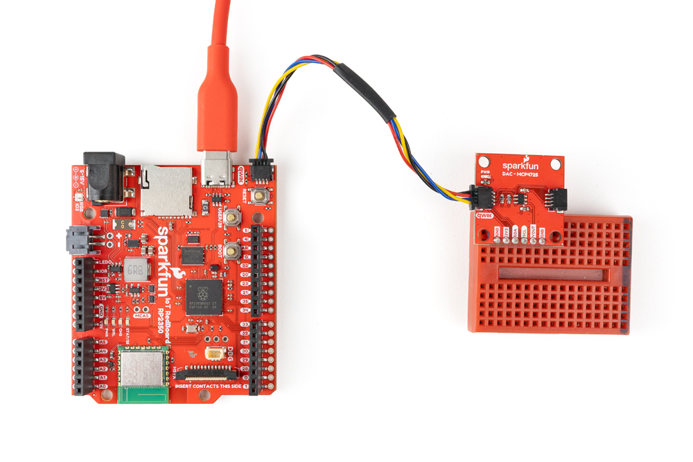
Next we'll plug the breakout into a breadboard and connect it to the RedBoard IoT - RP2350 with a Qwiic cable:
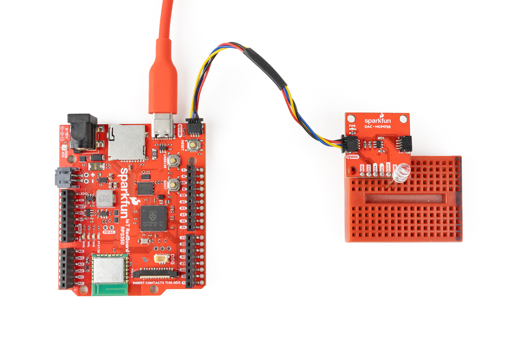
Finally, connect the LED to the analog voltage output pin (VO) and one of the ground pins:
Arduino Example
- Open the Arduino IDE.
- Open the Library Manager tool, search for "SparkFun AS1219" and install the latest version. This library was built using the SparkFun Toolkit so if you have not already installed it, search for "SparkFun Toolkit" in the Library Manager to install the dependency.
- Open "Example 3 - Triangle Wave".
- Select your Board (SparkFun RedBoard IoT - RP2350 or other board) and click "Upload".
- After the code compiles and finishes uploading, you should see the LED pulse on and off as the signal fluctuates like the video below:
[ ]
]