Introduction
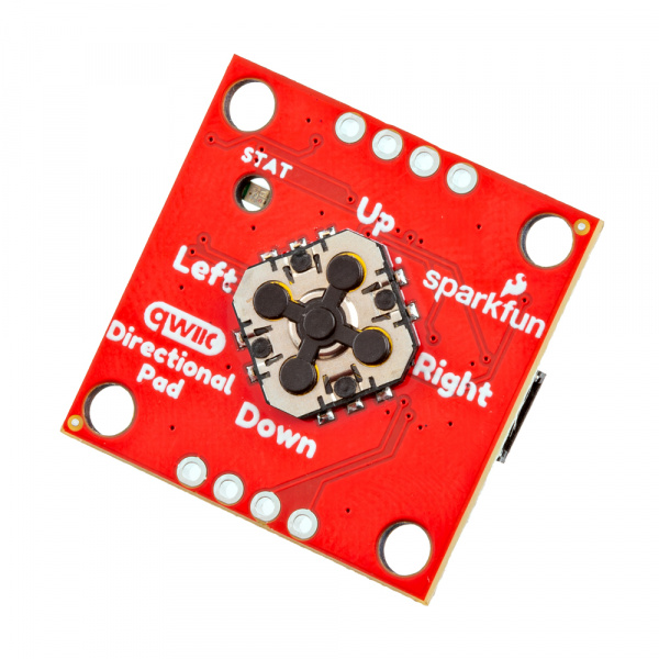
The SparkFun Qwiic Directional Pad adds a 5-way directional pad to your I2C bus! When connected to a microcontroller, press down on the directional pad (up, down, left, right, or center) to provide additional input for your application. The built-in RGB status LED provides visual feedback indicating which button is pressed.
In this tutorial, we'll go over the hardware and how to hookup the SparkFun Qwiic Directional Pad to an Arduino. We will also go over some Arduino examples to get started.
Required Materials
To follow along with this tutorial, you will need the following materials. You may not need everything though depending on what you have. Add it to your cart, read through the guide, and adjust the cart as necessary.
Qwiic Cables
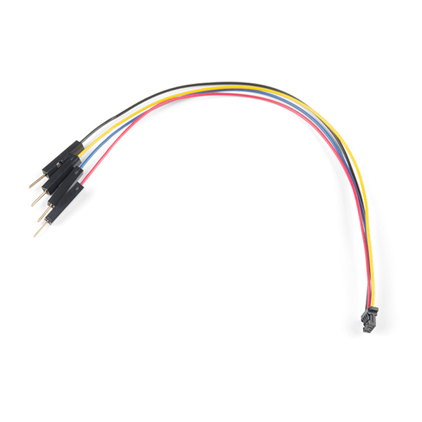
For those that want to take advantage of the Qwiic connector, you'll want to grab a Qwiic cable. There are a variety of other cable lengths available in the SparkFun catalog to choose from.
Tools (Optional)
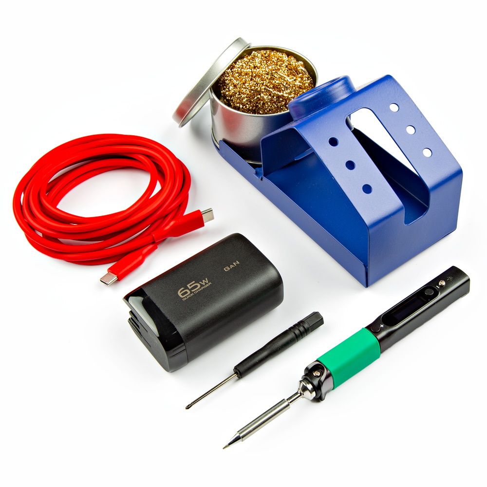
For users connecting to the plated through holes, you will need a soldering iron, solder, and general soldering accessories.
Prototyping Accessories (Optional)
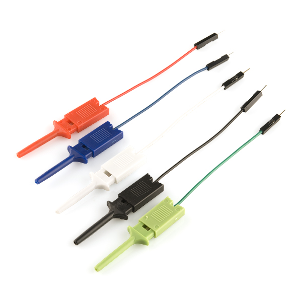
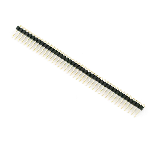
Depending on your setup, you may want to use IC hooks for a temporary connection. However, you will want to solder header pins to connect devices to the plated through holes for a secure connection.
Suggested Reading
If you aren't familiar with the Qwiic Connection System, we recommend reading here for an overview.
If you aren’t familiar with the following concepts, we also recommend checking out a few of these tutorials before continuing.
Hardware Overview
In this section, we will highlight the hardware and pins that are broken out on the SparkFun Qwiic Directional Pad. For more information, check out our Resources and Going Further on the components used on the breakout board.
Power
To power the board, you will need 3.3V. You can connect a Qwiic cable to the Qwiic connector on either side of the board or you can solder directly to the PTHs. Below are the power pins that are broken out on the edge of the board.
- 3V3 — This pin is the voltage input for the board. The recommended input voltage for this pin is 3.3V.
- GND — Of course, is the common, ground voltage (0V reference) for the system.
 |
 |
| Power and Ground Highlighted - Top View | Power, Ground, and Qwiic Connector Highlighted - Bottom View |
5-Way Directional Pad
A low profile 5-way directional pad is populated on the top side of the board. These buttons are small! We recommend using your fingernail when pressing down on a button. Each pad includes a momentary push button that is read by the PCA9554 8-bit I2C I/O expander that is populated on the bottom of the board.
Note
We recommend pressing only one button at a time! For example, if the UP button is pressed down, it will register the UP button being pressed down first due to the way the condition statements are written in the Arduino code. Once the UP button is released, the board will be able to read another button press. However, if the LEFT button is pressed and then the UP button is pressed, the Qwiic Directional Pad will register the UP button.
PCA9554 8-bit I2C I/O Expander
The TI PCA9554 that is populated on the bottom side of the board is an 8-bit I2C I/O expander that enables users to read and write to the following GPIO pins through I2C. It is used to read the 5-way directional pad or write to the non-addressable RGB LED. The I2C address of the PCA9554 is set to 0x20 by default. By adjusting the jumpers on the back of the board, the alternative address can be any value between 0x21 to 0x27.
- GPIO0 — GPIO0 is connected to the 5-way directional pad's UP button. A 10kΩ pull-up resistor is connected.
- GPIO1 — GPIO1 is connected to the 5-way directional pad's DOWN button. A 10kΩ pull-up resistor is connected.
- GPIO2 — GPIO3 is connected to the 5-way directional pad's RIGHT button. A 10kΩ pull-up resistor is connected.
- GPIO3 — GPIO4 is connected to the 5-way directional pad's LEFT button. A 10kΩ pull-up resistor is connected.
- GPIO4 — GPIO4 is connected to the 5-way directional pad's CENTER button. A 10kΩ pull-up resistor is connected.
- GPIO5 — GPIO5 is connected to the blue LED. The LED can be disconnected if users decide to use a different input to the GPIO5's PTH.
- GPIO6 — GPIO6 is connected to the green LED. The LED can be disconnected if users decide to use a different input to the GPIO6's PTH.
- GPIO7 — GPIO7 is connected to the red LED. The LED can be disconnected if users decide to use a different input to the GPIO7's PTH.
Qwiic and I2C
The board includes two horizontal Qwiic connectors to connect to other Qwiic-enabled I2C devices. However, the board still breaks out 0.1"-spaced pins for users who prefer a soldered connection.
- SCL — I2C clock on the PCA9554.
- SDA — I2C data on the PCA9554.
As explained in the previous section, the I2C address of the PCA9554 is set to 0x20 by default. By adjusting the jumpers on the back of the board, the alternative address can be any value between 0x21 to 0x27. Make sure to check the Jumpers section below for more information.
Interrupt
The interrupt pin labeled as INT is for users that want to notify a microcontroller that there is a button being pressed down on the 5-way directional pad. This pin is active low.
LEDs
The board includes two LEDs on the top and bottom of the board. Both can be disabled with the jumpers on the back of the board.
- PWR — On the bottom side of the board, the power LED indicates when power is available on 3.3V.
- STAT — The status LED is a non-addressable RGB LED that is used to indicate which button is being pressed on the 5-way directional pad. While this is populated on the bottom of the board, it will light up through the hole toward the top side of the board. Each channel can be disabled with the jumper on the back for users that want to connect them to some other input. Note that two colors were not used since there were only 5 buttons available on the directional pad.
| Button Press | Color | Red (GPIO7) |
Green (GPIO6) |
Blue (GPIO5) |
|---|---|---|---|---|
| Up | Red | 1 | 0 | 0 |
| Down | Green | 0 | 1 | 0 |
| Left | Magenta | 1 | 0 | 1 |
| Right | Cyan | 0 | 1 | 1 |
| Center | White | 1 | 1 | 1 |
| No Button Press | OFF | 0 | 0 | 0 |
| Not Assigned | Blue | 0 | 0 | 1 |
| Not Assigned | Yellow | 1 | 1 | 0 |
Jumpers
Note
If this is your first time working with jumpers, check out the How to Work with Jumper Pads and PCB Traces tutorial for more information.
The back of the board includes jumpers to configure the board.
- PWR — By default, the power jumper connects the LED to the output's 3.3V pin. Cutting this trace disables the LED.
- 7 — By default, this jumper is closed. Cutting this jumper will disconnect GPIO7 and the red channel from the RGB LED. Once disabled, GPIO7 is available for users that want to connect them to some other input.
- 6 — By default, this jumper is closed. Cutting this jumper will disconnect GPIO6 and the green channel from the RGB LED. Once disabled, GPIO6 is available for users that want to connect them to some other input.
- 5 — By default, this jumper is closed. Cutting this jumper will disconnect GPIO5 and the blue channel from the RGB LED. Once disabled, GPIO5 is available for users that want to connect them to some other input.
- I2C — By default, this three-pad jumper is closed. The three way jumper labeled I2C connects 3.3V to two 2.2kΩ pull-up resistors and to the I2C data and clock lines. If multiple devices are connected to the bus with the pull-up resistors enabled, the parallel equivalent resistance will create too strong of a pull-up for the bus to operate correctly. As a general rule of thumb, disable all but one pair of pull-up resistors if multiple devices are connected to the bus.
- ADR — By default, the three jumpers 0, 1, and 2 are open. These set the I2C address of the Qwiic Directional Pad. Adding a solder blob will close the jumper and set the jumper as a
1. Below shows the table needed to configure the three jumpers to achieve the desired I2C address.
| I2C Address | ADR2 (Jumper 2) |
ADR1 (Jumper 1) |
ADR0 (Jumper 0) |
|---|---|---|---|
| 0x20 | 0 | 0 | 0 |
| 0x21 | 0 | 0 | 1 |
| 0x22 | 0 | 1 | 0 |
| 0x23 | 0 | 1 | 1 |
| 0x24 | 1 | 0 | 0 |
| 0x25 | 1 | 0 | 1 |
| 0x26 | 1 | 1 | 0 |
| 0x27 | 1 | 1 | 1 |
3D Model
A 3D model of the board and components was exported to a STEP file using KiCad.
Board Dimensions
The board is 1.0" x 1.0" (25.4mm x 25.4mm). There are 2x mounting holes. You can use 4-40 standoffs to mount the board to a panel or enclosure.
Hardware Hookup
In this section, we will go over how to connect to the Qwiic Directional Pad.
Connecting Via Qwiic
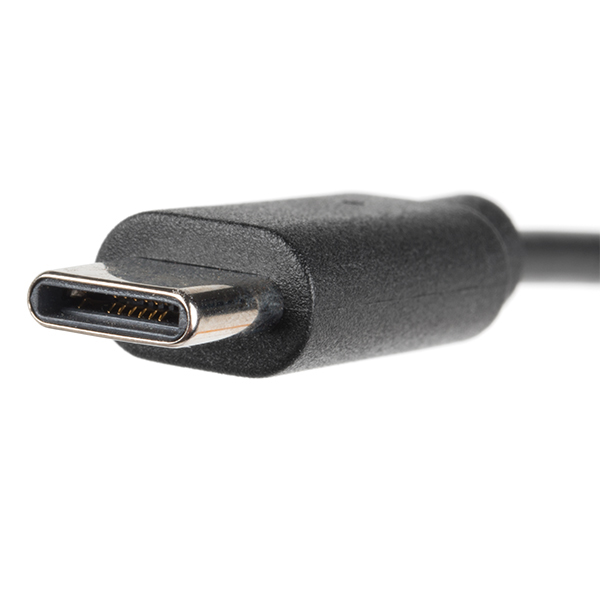
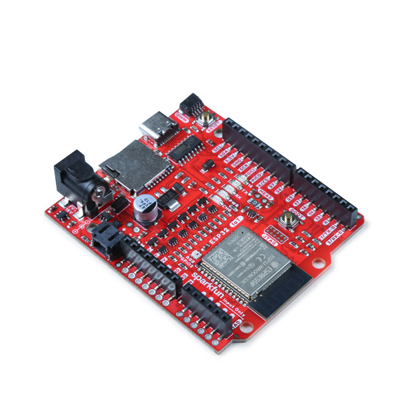
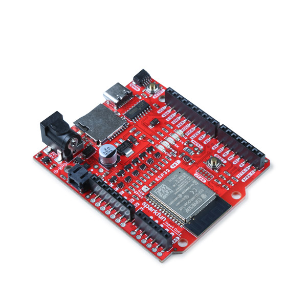
Insert a Qwiic cable between your Arduino microcontroller and the Qwiic Directional Pad. In this case, we used the SparkFun IoT RedBoard - ESP32 Development Board for the Arduino microcontroller. When ready, connect a USB cable to the Arduino to program, power, and view serial messages.
Connecting via PTH
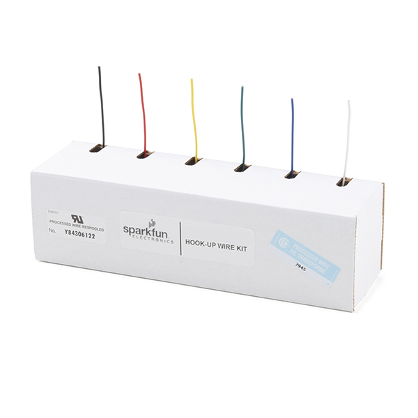
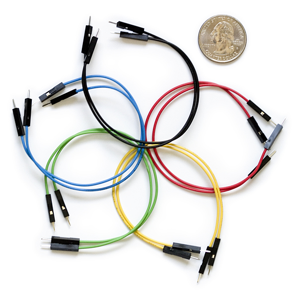
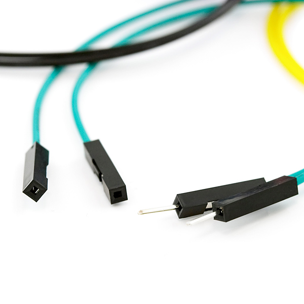
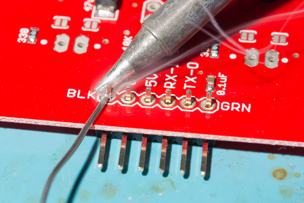
For temporary connections to the PTHs, you could use IC hooks to test out the pins. However, you'll need to solder headers or wires of your choice to the board for a secure connection. You can choose between a combination of header pins and jumper wires, or stripping wire and soldering the wire directly to the board.
Interrupt
For users that want to notify the microcontroller that there is a button press, you could connect the INT pin to one of the Arduino's interrupts. In this case, we connected the Directional Pad's INT pin to IoT RedBoard's pin 4.
Note
Example 3 from the SparkFun I2C Expander Arduino Library uses the IoT RedBoard - ESP32's pin 14 for the interrupt. The example in this tutorial is slightly different and uses pin 4 for the interrupt.
Setting Up Arduino
Arduino
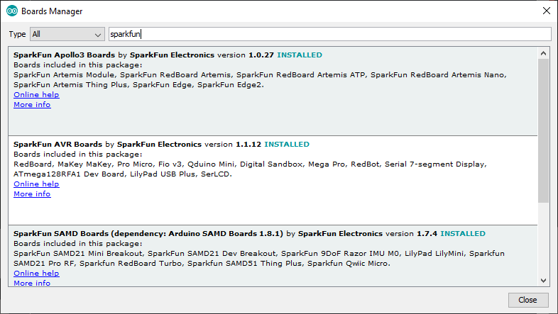
This example assumes you are using the latest version of the Arduino IDE on your desktop. If this is your first time using Arduino IDE, library, or board add-on, please review the following tutorials.
Note
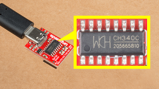
If you've never connected an CH340 device to your computer before, you may need to install drivers for the USB-to-serial converter. Check out our section on "How to Install CH340 Drivers" for help with the installation.
SparkFun has written basic examples for the Qwiic Directional Pad and is provided in the GitHub Hardware repository.
You will need the SparkFun I2C Expander Arduino Library to work with the Qwiic Directional Pad's basic examples. You can obtain this library through the Arduino Library Manager by searching for "SparkFun I2C Expander Arduino Library". Find the one written by SparkFun Electronics and install the latest version. Users who prefer to manually install the library can get it from the GitHub Repository or download the .ZIP by clicking the button below:
Arduino Examples
Now that we have our library and board add-on installed, we can start experimenting with the breakout board. For the scope of this tutorial, we will highlight the examples provided in the GitHub hardware repo to get started.
Example 1: Read Buttons, Write LEDs
From your downloads, open the example labeled as Example1-ReadButtons_WriteLEDs.ino. This example reads the button presses and writes to the non-addressable LED using the PCA9554 I/O I2C Expander.
For users using an Arduino microcontroller, select your board in the Tools menu (in our case the SparkFun ESP32 IoT RedBoard) and the correct Port it enumerated on.
You can also copy or paste the code as shown below. Then click "Upload".
/*
  Using the Qwiic Directional Pad
  By: Nathan Seidle
  SparkFun Electronics
  Date: October 8th, 2024

  License: This code is public domain but you buy me a beer if you use this and we meet someday (Beerware license).

  Feel like supporting our work? Buy a board from SparkFun!
  https://www.sparkfun.com/products/14733

  This example demonstrates how to use pinMode and digitalRead/Write to read the directional pad and turn
  on/off the RGB LED channels.

  Hardware Connections:
  Plug the Qwiic board to your Arduino/ESP32 or other
  Press the buttons
  Watch each LED turn on one-at-a-time
*/

#include <SparkFun_I2C_Expander_Arduino_Library.h> // Click here to get the library: http://librarymanager/All#SparkFun_I2C_Expander_Arduino_Library

SFE_PCA95XX io; // Defaults to the PCA9554 at I2C address 0x20

int buttonUp = 0;
int buttonDown = 1;
int buttonRight = 2;
int buttonLeft = 3;
int buttonCenter = 4;
int ledBlue = 5;
int ledGreen = 6;
int ledRed = 7;

void setup()
{
  Serial.begin(115200);
  delay(250);
  Serial.println("Qwiic Directional Pad Example");

  Wire.begin();

  // Initialize the PCA9554, default address = 0x20
  if (io.begin() == false) //Device Address, Number of GPIO
  {
    Serial.println("PCA9554 not detected. Please check wiring. Freezing...");
    while (1)
      ;
  }

  io.pinMode(buttonUp, INPUT);
  io.pinMode(buttonDown, INPUT);
  io.pinMode(buttonLeft, INPUT);
  io.pinMode(buttonRight, INPUT);
  io.pinMode(buttonCenter, INPUT);
  io.pinMode(ledRed, OUTPUT);
  io.pinMode(ledGreen, OUTPUT);
  io.pinMode(ledBlue, OUTPUT);

  redOff();
  greenOff();
  blueOff();

  Serial.println("Qwiic Directional Pad online!");
}

void loop()
{
  Serial.print("Button: ");

  if (io.digitalRead(buttonUp) == LOW)
  {
    Serial.print("Up");
    redOn();
    greenOff();
    blueOff();
  }
  else if (io.digitalRead(buttonDown) == LOW)
  {
    Serial.print("Down");
    redOff();
    greenOn();
    blueOff();
  }
  else if (io.digitalRead(buttonLeft) == LOW)
  {
    Serial.print("Left");
    redOn();
    greenOff();
    blueOn();
  }
  else if (io.digitalRead(buttonRight) == LOW)
  {
    Serial.print("Right");
    redOff();
    greenOn();
    blueOn();
  }
  else if (io.digitalRead(buttonCenter) == LOW)
  {
    Serial.print("Center");
    redOn();
    greenOn();
    blueOn();
  }
  else
  {
    Serial.print(" None");
    redOff();
    greenOff();
    blueOff();
  }
  Serial.println();

  delay(100);
}

void redOn()
{
  io.digitalWrite(ledRed, LOW);
}
void redOff()
{
  io.digitalWrite(ledRed, HIGH);
}
void greenOn()
{
  io.digitalWrite(ledGreen, LOW);
}
void greenOff()
{
  io.digitalWrite(ledGreen, HIGH);
}
void blueOn()
{
  io.digitalWrite(ledBlue, LOW);
}
void blueOff()
{
  io.digitalWrite(ledBlue, HIGH);
}
After uploading the code, open the Serial Monitor or terminal emulator of your choice with the baud rate set to 115200. Press down on any of the buttons. You will notice a serial output indicating which button was pressed in the Arduino Serial Monitor. Looking to the board, you will notice the LED changing color with respect to the button press.
Example 2: Interrupt Pin
Note
Example 3 from the SparkFun I2C Expander Arduino Library uses the IoT RedBoard - ESP32's pin 14 for the interrupt. The example in this tutorial is slightly different and uses pin 4 for the interrupt.
From your downloads, open the example labeled as Example2_InterruptReadButtons_WriteLEDs.ino. This example reads the button presses and writes to the non-addressable LED whenever there is an interrupt using the PCA9554 I/O I2C Expander. Make sure to connect the Qwiic Directional Pad's interrupt pin to the IoT RedBoard's pin 4.
For users using an Arduino microcontroller, select your board in the Tools menu (in our case the SparkFun ESP32 IoT RedBoard) and the correct Port it enumerated on.
You can also copy or paste the code as shown below. Then click "Upload".
/*
  Using the PCA9554 with Interrupts
  Modified by: Ho Yun "Bobby" Chan
  Orignally Written By: Nathan Seidle
  SparkFun Electronics
  Date: November 22nd, 2024

  License: This code is public domain but you buy me a beer if you use this and we meet someday (Beerware license).

  Feel like supporting our work? Buy a board from SparkFun!
  https://www.sparkfun.com/products/17047 - Qwiic GPIO
  https://www.sparkfun.com/products/26784 - Qwiic Power Switch
  https://www.sparkfun.com/products/26851 - Qwiic Directional Pad

  This example demonstrates how to use interrupts to check for new pin changes on the Qwiic Directional Pad
  and turn on/off the RGB LED channels

  Hardware Connections:
  Plug the Qwiic Directional Pad into a Qwiic enabled board (SparkFun Thing Plus C, RedBoard, RedBoard IoT, etc)
  If you don't have a platform with a Qwiic connection use the SparkFun Qwiic Breadboard Jumper (https://www.sparkfun.com/products/17912)
  Connect a wire from a GPIO pin that is interrupt capable to the !INT pin on the Qwiic Directional Pad
  Open the serial monitor at 115200 baud to see the output.
*/

#include <SparkFun_I2C_Expander_Arduino_Library.h>  // Click here to get the library: http://librarymanager/All#SparkFun_I2C_Expander_Arduino_Library

//SFE_PCA95XX io(PCA95XX_PCA9534); // Create a PCA9534 - Has interrupt pin
//SFE_PCA95XX io(PCA95XX_PCA9536); // Create a PCA9536 - Has optional interrupt pin
//SFE_PCA95XX io(PCA95XX_PCA9537); // Create a PCA9537 - Has interrupt pin
SFE_PCA95XX io(PCA95XX_PCA9554);  // Create a PCA9554 - Has interrupt pin
//SFE_PCA95XX io(PCA95XX_PCA9556); // Create a PCA9556 - No interrupt pin / Not compatible with this code
//SFE_PCA95XX io(PCA95XX_PCA9557); // Create a PCA9557 - No interrupt pin / Not compatible with this code

int buttonUp = 0;
int buttonDown = 1;
int buttonRight = 2;
int buttonLeft = 3;
int buttonCenter = 4;
int ledBlue = 5;
int ledGreen = 6;
int ledRed = 7;

int gpioExpander_interrupt = 4;  //INT of PCA9554 is connected to ESP pin 4. Goes low when an input pin changes.

bool buttonPressed = false;

//Interrupt that is called when INT pin goes low
void IRAM_ATTR gpioExpanderISR() {
  buttonPressed = true;
}

void setup() {
  Serial.begin(115200);
  delay(250);
  Serial.println("Qwiic Directional Pad Example");

  Wire.begin();

  // Initialize the PCA95xx with its default I2C address
  if (io.begin() == false) {
    Serial.println("PCA9554 not detected. Please check wiring. Freezing...");
    while (1)
      ;
  }
  pinMode(gpioExpander_interrupt, INPUT_PULLUP);

  io.pinMode(buttonUp, INPUT);
  io.pinMode(buttonDown, INPUT);
  io.pinMode(buttonLeft, INPUT);
  io.pinMode(buttonRight, INPUT);
  io.pinMode(buttonCenter, INPUT);
  io.pinMode(ledRed, OUTPUT);
  io.pinMode(ledGreen, OUTPUT);
  io.pinMode(ledBlue, OUTPUT);

  redOff();
  greenOff();
  blueOff();

  Serial.println("Qwiic Directional Pad online!");

  attachInterrupt(gpioExpander_interrupt, gpioExpanderISR, CHANGE);
}

void loop() {
  //Wait for interrupt to fire
  if (buttonPressed == true) {
    Serial.println("Interrupt! ");
    //Get all the pins in one read to save time
    uint8_t currentState = io.getInputRegister();
    // Pins are pulled high so when we see low, button is being pressed
    if ((currentState & (1 << buttonUp)) == 0) {
      Serial.println("Up");

      //RED
      redOn();
      greenOff();
      blueOff();
    } else if ((currentState & (1 << buttonDown)) == 0) {
      Serial.println("Down");

      //GREEN
      redOff();
      greenOn();
      blueOff();
    } else if ((currentState & (1 << buttonLeft)) == 0) {
      Serial.println("Left");

      //MAGENTA
      redOn();
      greenOff();
      blueOn();
    } else if ((currentState & (1 << buttonRight)) == 0) {
      Serial.println("Right");

      //CYAN
      redOff();
      greenOn();
      blueOn();
    } else if ((currentState & (1 << buttonCenter)) == 0) {
      Serial.println("Center");

      //WHITE
      redOn();
      greenOn();
      blueOn();
    } else {
      Serial.println(" None");

      //OFF
      redOff();
      greenOff();
      blueOff();
    }

    buttonPressed = false;
  }
}


void redOn() {
  io.digitalWrite(ledRed, LOW);
}
void redOff() {
  io.digitalWrite(ledRed, HIGH);
}
void greenOn() {
  io.digitalWrite(ledGreen, LOW);
}
void greenOff() {
  io.digitalWrite(ledGreen, HIGH);
}
void blueOn() {
  io.digitalWrite(ledBlue, LOW);
}
void blueOff() {
  io.digitalWrite(ledBlue, HIGH);
}
After uploading the code, open the Serial Monitor or terminal emulator of your choice with the baud rate set to 115200. Press down on any of the buttons. You will notice a serial output indicating which button was pressed in the Arduino Serial Monitor whenever there is a button press. Looking to the board, you will notice the LED changing color with respect to the button press.
Troubleshooting
General Troubleshooting Help
Note
Not working as expected and need help?
If you need technical assistance and more information on a product that is not working as you expected, we recommend heading on over to the SparkFun Technical Assistance page for some initial troubleshooting.
If you don't find what you need there, the SparkFun Forums are a great place to find and ask for help. If this is your first visit, you'll need to create a forum account to search product forums and post questions.
Resources
Now that you've successfully got your SparkFun Qwiic Directional Pad up and running, it's time to incorporate it into your own project! For more information, check out the resources below:
- Schematic (PDF)
- KiCad Files (ZIP)
- 3D Model (STEP)
- Board Dimensions (PNG)
- Component Datasheets
- Arduino Library
- Arduino Example Code
- GitHub Hardware Repo
Or check out the Qwiic Button or Qwiic Joystick for more ideas!
