Getting Started
Introduction

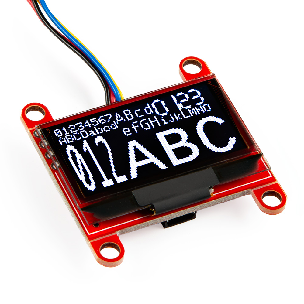
The SparkFun Qwiic OLED Arduino Library is a single graphics module that supports all SparkFun OLED boards based on the SSD1306 from Solomon Systech. Prior to this library, three different libraries were used to support our four different OLED boards.
The SparkFun Qwiic OLED Library delivers a common implementation for all our Qwiic OLED products, delivering a unified, fast, and efficient solution that implements a familiar and easy to understand user experience.
Key Features
- Implements common graphics capabilities: pixel, line, rectangle, filled rectangle, circle, filled circle, bitmap, text and raster operators (i.e. XOR).
- Smart data transfer to the device – only sends dirty regions of the graphics buffer to the OLED device, not the entire buffer.
- High performance – 2x faster than our previous OLED library, often much higher.
- Efficient memory usage. No dynamic memory utilized. Static resources are loaded once, and only on explicit declaration.
- Implements a familiar interface, making migration from older libraries straight forward
Getting Started
The Software Setup outlines library installation and the general use of the Qwiic OLED library.
Detailed examples are included as part of the library installation process and available in the Arduino IDE menu: File > Examples > SparkFun Qwiic OLED Arduino Library. A walk-thru of key examples is contained in the Examples section of this documentation set.
Note
For v1.0.5 of the SparkFun Qwiic OLED Arduino Library, we named the library as SparkFun Qwiic OLED Graphics Library. After v1.0.6, we updated the name to say SparkFun Qwiic OLED Arduino Library. You may have multiple versions in your Arduino libraries folder if you installed the library more than once. To avoid confusion, issues compiling, and to use the latest version, we recommend removing the "SparkFun Qwiic OLED Graphics Library" folder should you decide to use the latest and greatest version. This will probably be located under ..Documents\Arduino\libraries, that is if you are using Windows.
Note
Note that we have more than one Arduino Library for the micro OLED. If you have the older Arduino Library, make sure to not confuse the two libraries. You will notice that the older library will be called "SparkFun Micro OLED Breakout". The example code will include the following line of code: #include <SFE_MicroOLED.h>.
A full API Reference is also provided for the library.
Supported Products
The SparkFun Qwiic OLED Arduino Library supports the following SparkFun products.
Supported Microcontrollers - Arduino Environment
The following architectures are supported in the Arduino Library.
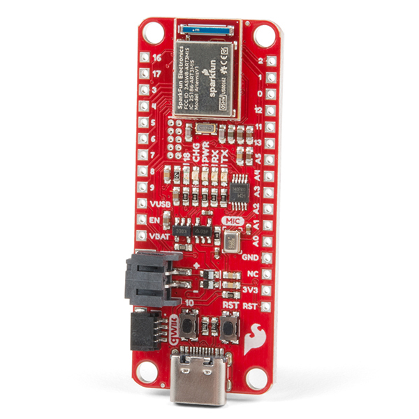
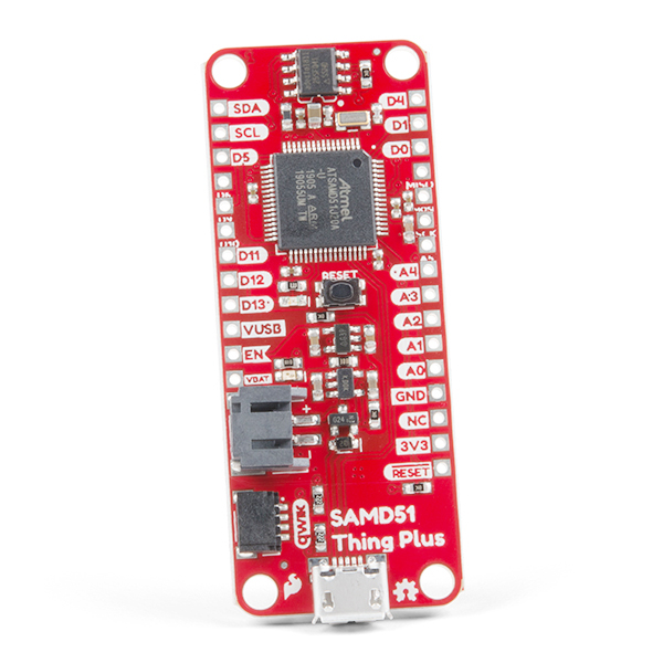
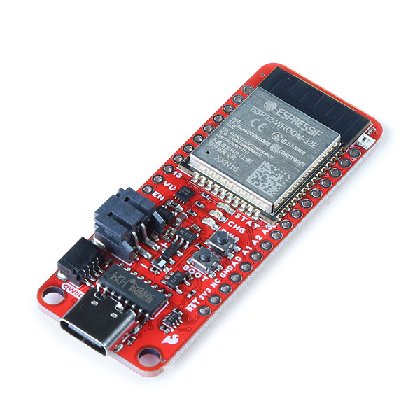
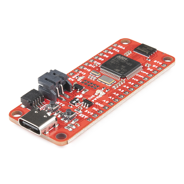
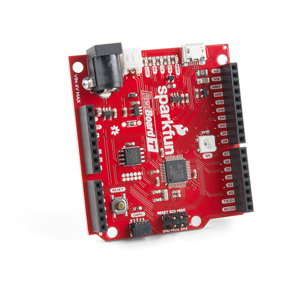
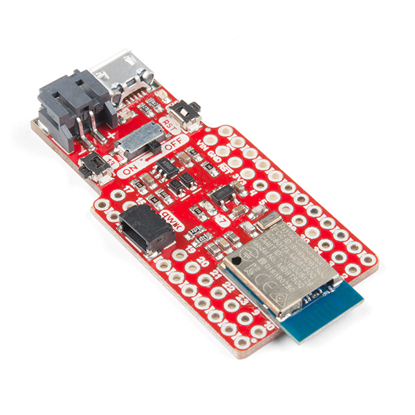
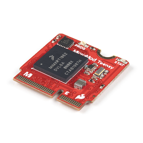
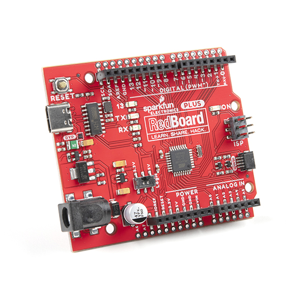
Below are a few of those processors populated on Arduino boards from the SparkFun catalog. You will need to make sure to check the associated hookup guides for additional information about compatible cables, drivers, or board add-ons.
Note
Unfortunately, the ATmega32U4 is not supported under this library. We recommend either using a different microcontroller or rolling back to the previous library written for the display.
License
The SparkFun Qwiic OLED Arduino Library is licensed using the Open Source MIT License:
The MIT License (MIT)

Copyright (c) 2015 SparkFun Electronics

Permission is hereby granted, free of charge, to any person obtaining a copy
of this software and associated documentation files (the "Software"), to deal
in the Software without restriction, including without limitation the rights
to use, copy, modify, merge, publish, distribute, sublicense, and/or sell
copies of the Software, and to permit persons to whom the Software is
furnished to do so, subject to the following conditions:

The above copyright notice and this permission notice shall be included in all
copies or substantial portions of the Software.

THE SOFTWARE IS PROVIDED "AS IS", WITHOUT WARRANTY OF ANY KIND, EXPRESS OR
IMPLIED, INCLUDING BUT NOT LIMITED TO THE WARRANTIES OF MERCHANTABILITY,
FITNESS FOR A PARTICULAR PURPOSE AND NONINFRINGEMENT. IN NO EVENT SHALL THE
AUTHORS OR COPYRIGHT HOLDERS BE LIABLE FOR ANY CLAIM, DAMAGES OR OTHER
LIABILITY, WHETHER IN AN ACTION OF CONTRACT, TORT OR OTHERWISE, ARISING FROM,
OUT OF OR IN CONNECTION WITH THE SOFTWARE OR THE USE OR OTHER DEALINGS IN THE
SOFTWARE.
Qwiic Micro OLED (0.66", 64x48)
Introduction
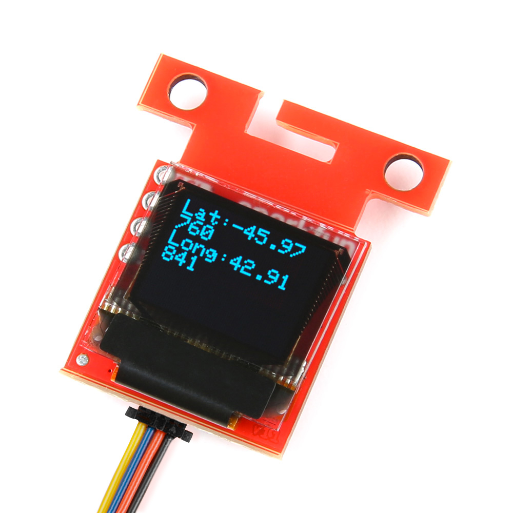
The Qwiic Micro OLED is a Qwiic enabled version of our micro OLED display! This small monochrome, blue-on-black OLED display displays incredibly clear images.
This hookup guide will show you how to get started drawing objects and characters on your OLED.
Required Materials
To follow along with this tutorial, you will need the following materials. You may not need everything though depending on what you have. Add it to your cart, read through the guide, and adjust the cart as necessary.
- 1x SparkFun RedBoard Plus [DEV-18158]
- 1x Reversible USB A to C Cable - 0.8m [CAB-15425]
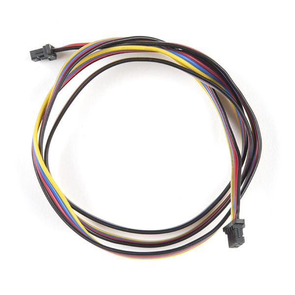
- 1x Qwiic Cable
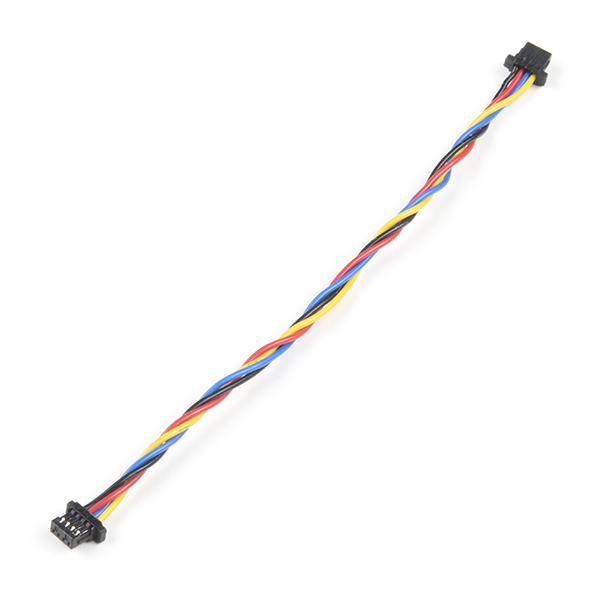
- Flexible Qwiic Cable - 50mm [PRT-17260], for short distances
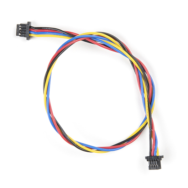
- Flexible Qwiic Cable - 500mm [PRT-17257], for those that need to wire the board farther away from your microcontroller
- 1x SparkFun Micro OLED Breakout (Qwiic) [LCD-22495]
Microcontroller
To get started, you'll need a microcontroller to, well, control everything. We used the RedBoard with the ATmega328P for the Qwiic micro OLED. However, any of the other microcontrollers that are compatible with the Qwiic OLED Arduino Library will work as well. Below are a few from the list that we provided earlier.
USB Cable
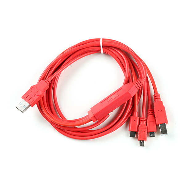
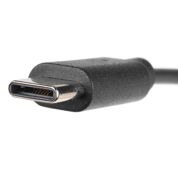
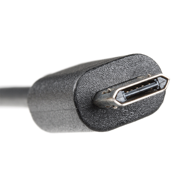
Below are a few USB cables from the SparkFun catalog. Make sure to grab the associated USB cable that is compatible with your microcontroller.
Qwiic
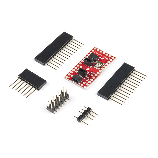
If the controller you choose doesn't have a built-in Qwiic connector, one of the following Qwiic shields that matches your preference of microcontroller is needed:
You will also need a Qwiic cable to connect the shield to your OLED, choose a length that suits your needs.
Of course, you will also need a Qwiic Micro OLED if you have not added that to you cart already.
Suggested Reading
If you aren't familiar with the Qwiic Connection System, we recommend reading here for an overview.
We would also recommend taking a look at the following tutorials if you aren't familiar with them.
Hardware Overview
Listed below are some of the operating ranges and characteristics of the Qwiic Micro OLED.
| Characteristic | Range |
|---|---|
| Voltage | 3.3V |
| Temperature | -40°C to 85°C |
| I2C Address | 0X3D (Default) or 0X3C (Closed Jumper) |
Pins
Power and I2C pins are broken out to the 1x4 PTH pins as well as the two horizontal Qwiic connectors.
| Pin | Description | Direction |
|---|---|---|
| GND | Ground | In |
| 3.3V | Power | In |
| SDA | I2C Data | In |
| SCL | I2C Clock | In |
Jumpers
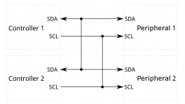
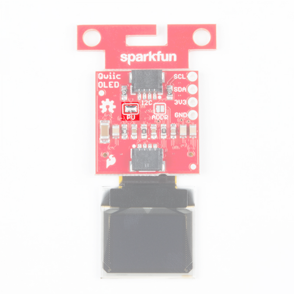
There are several jumpers on board that can be changed to facilitate several different functions. The first of which is the I2C pull-up jumper to disable the 2.2kΩ pull up resistors on the I2C data and clock lines, highlighted below. If multiple boards are connected to the I2C bus, the equivalent resistance goes down, increasing your pull up strength. If multiple boards are connected on the same bus, make sure only one board has the pull-up resistors connected.
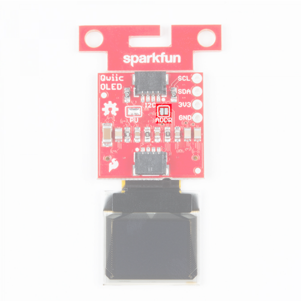
The ADDR jumper (highlighted below) can be used to change the I2C address of the board. The default jumper is open by default, pulling the address pin high and giving us an I2C address of 0X3D. Closing this jumper will ground the address pin, giving us an I2C address of 0X3C.
Board Dimensions
Revision Change
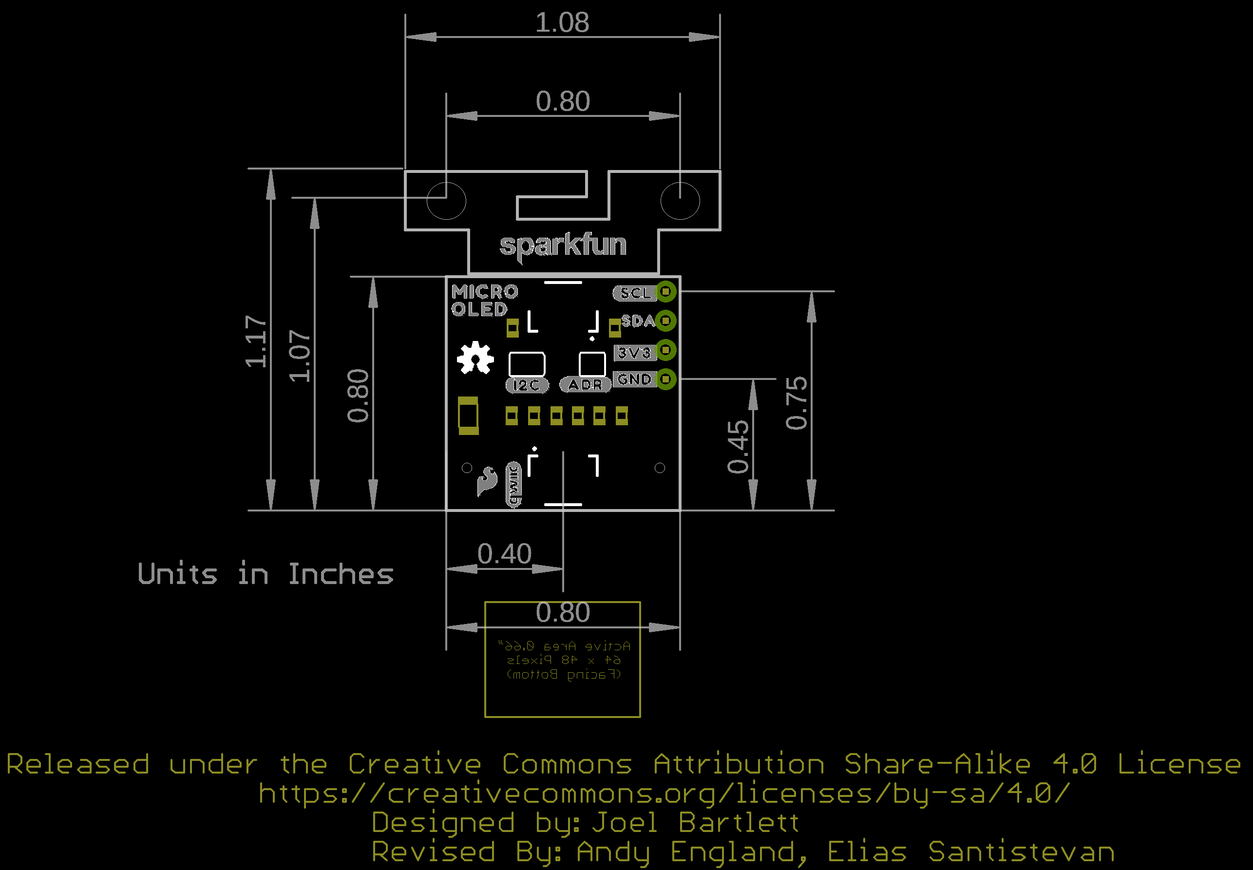
For V11, we have optimized the two mounting hole locations to match the mounting holes located on a standard 1.0" x 1.0" Qwiic-sized board. The overall functionality of the Qwiic Micro OLED breakout board is the same as the previous version!
The overall board size is 1.08" x 1.17". There is a v-score for users that want to remove the mounting holes.
Hardware Assembly
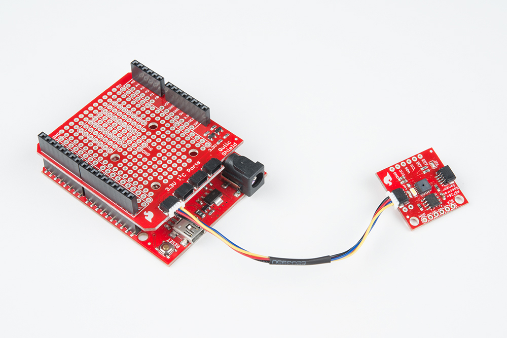
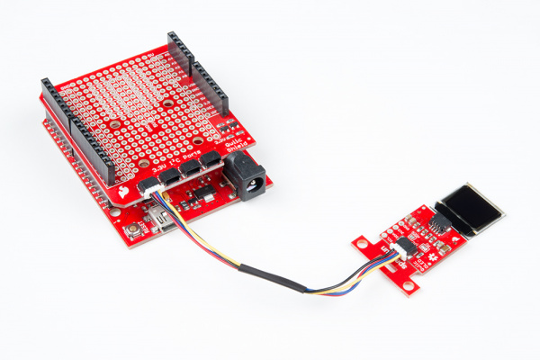
If you haven't yet assembled your Qwiic Shield, now would be the time to head on over to that tutorial. With the shield assembled, SparkFun's Qwiic environment means that connecting the screen could not be easier. Just plug one end of the Qwiic cable into the OLED display, the other into the Qwiic Shield and you'll be ready to start displaying images on your little display.
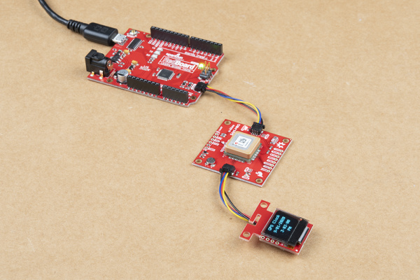
If you have a built-in Qwiic connector, you can skip the hardware assembly of the Qwiic Shield and simply insert a Qwiic cable between the two boards. Have more than one Qwiic-enabled device? You can daisy chain it to the board as well! Below is an example with the SAM-M8Q and the Qwiic Micro OLED daisy chained together to the RedBoard Qwiic.
Note
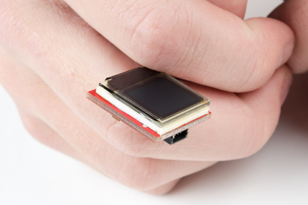
The initial launch of the Qwiic micro OLED breakout board had the OLED loosely attached to the breakout board. For users that received those boards, be careful handling it! You can either use your own enclosure for the OLED display, or you can use some double sided foam tape for a less permanent solution.
The current production of the boards includes the double sided foam tape.
Software
The SparkFun Micro OLED Breakout (Qwiic) uses the SparkFun QWIIC OLED Arduino Library. The SparkFun Qwiic OLED library Getting Started guide has library setup instructions and usage examples. Additionally, the full library API documentation is available in the SparkFun Qwiic OLED Library API Reference guide.
Resources
Now that you've successfully got your OLED displaying things, it's time to incorporate it into your own project!
For more on the Qwiic Micro OLED, check out the links below:
- Schematic (PDF)
- Eagle Files (ZIP)
- Datasheet (PDF)
- Bitmap Generator
- Qwiic System Landing Page
- Qwiic Micro OLED Python Package
- GitHub Hardware Repo -- Board design files for the Qwiic Micro OLED.
- Product Showcase: Qwiic Presence Sensor & OLED
Qwiic Transparent Graphical OLED (1.51", 128x56)
Introduction
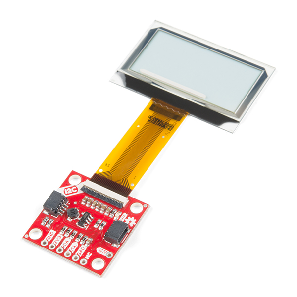
The future is here! You asked and we delivered - our Qwiic Transparent Graphical OLED Breakout allows you to display custom images on a transparent screen using either I2C or SPI connections.
With Qwiic connectors it's quick (ha ha) and easy to get started with your own images. However, we still have broken out 0.1"-spaced pins in case you prefer to use a breadboard. Brilliantly lit in the dark and still visible by daylight, this OLED sports a display area of 128x64 pixels, 128x56 of which are completely transparent. Control of the OLED is based on the HyperDisplay library or SparkFun Qwiic OLED Arduino Library! For the scope of this tutorial, we will be using the SparkFun Qwiic OLED Arduino Library.
This hookup guide will show you how to get started drawing objects and characters on your OLED.
Required Materials
To follow along with this tutorial, you will need the following materials. You may not need everything though depending on what you have. Add it to your cart, read through the guide, and adjust the cart as necessary.
- 1x SparkFun Thing Plus - ESP32 WROOOM (USB-C) [WRL-20168]
- 1x Reversible USB A to C Cable - 0.8m [CAB-15425]
- 1x Qwiic Cable
- Flexible Qwiic Cable - 50mm [PRT-17260], for short distances
- Flexible Qwiic Cable - 500mm [PRT-17257], for those that need to wire the board farther away from your microcontroller
- 1x SparkFun Transparent Graphical OLED Breakout (Qwiic)[LCD-15173]
Microcontroller
To get started, you'll need a microcontroller to, well, control everything. We used the SparkFun Thing Plus - ESP32 WROOOM. However, any of the other microcontrollers that are compatible with the Qwiic OLED Arduino Library will work as well. Below are a few from the list that we provided earlier.
USB Cable
Below are a few USB cables from the SparkFun catalog. Make sure to grab the associated USB cable that is compatible with your microcontroller.
Qwiic
If the controller you choose doesn't have a built-in Qwiic connector, one of the following Qwiic shields that matches your preference of microcontroller is needed:
You will also need a Qwiic cable to connect the shield to your OLED, choose a length that suits your needs.
Of course, you will also need A Tranparent Graphical OLED Breakout if you have not added that to you cart already.
Suggested Reading
If you aren't familiar with the Qwiic Connection System, we recommend reading here for an overview.
We would also recommend taking a look at the following tutorials if you aren't familiar with them.
Hardware Overview
Listed below are some of the operating ranges and characteristics of the Transparent Graphical OLED Breakout.
| Characteristic | Range |
|---|---|
| Voltage | 1.65V-3.3V, typically 3.3V via the Qwiic Cable |
| Supply Current | 400 mA |
| I2C Address | 0X3C (Default), 0X3D (Closed Jumper) |
Graphical Display
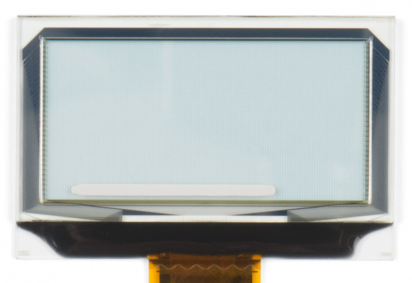
The graphical display is where all the fun stuff happens. The glass itself measures 42mm x 27.16mm, with a pixel display that is 35.5 x 18mm. It houses 128x64 pixels, 128x56 of which are transparent.
Qwiic Connectors
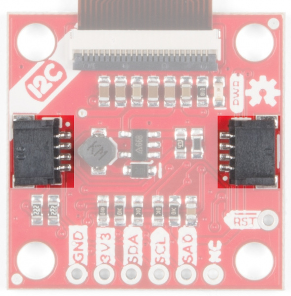
There are two Qwiic connectors on the board such that you can daisy-chain the boards should you choose to do so. If you're unfamiliar with our Qwiic Connect System, head on over to our Qwiic page to see the advantages!
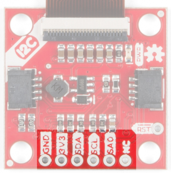
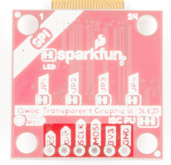
GPIO Pins
When you look at the GPIO pins, you'll notice that the labels are different from one side to the other. One side is labeled for I2C, the other side is labeled for SPI.
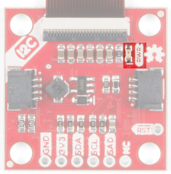
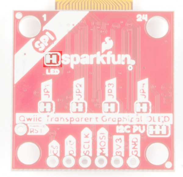
Power LED
This bad boy will light up when the board is powered up correctly.
You can disable the power LED by cutting the LED jumpers on the back of the board.
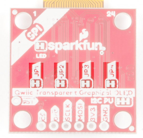
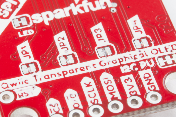
JPX Jumpers
The JPX jumpers are used to either change the I2C address or configure the board to use SPI communications. The other two jumpers allow you to disconnect the power LED and to disconnect the I2C pull-up resistors when chaining several Qwiic devices.
| Jumper | Function |
|---|---|
| JP1 | Holds the Chip Select line low when closed. Close for I2C, open for SPI |
| JP2 | Selects the address in I2C mode. Closed for 0x30 by default and open for 0x31. Open for SPI mode to release the D/C pin |
| JP3 | Used to select I2C or SPI mode. Close for I2C, open for SPI |
| JP4 | This jumper should be closed for I2C and open for SPI. This connection allows SDA to be bi-directional |
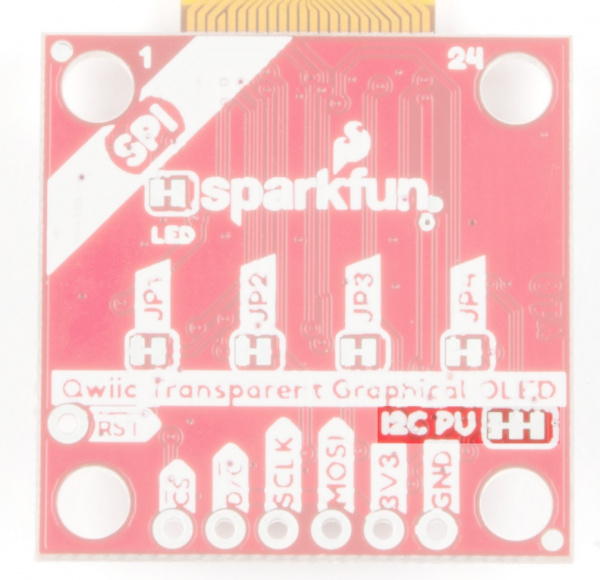
I2C Pull-Up Jumper
I2C devices contain open drains so we include resistors on our boards to allow these devices to pull pins high. This becomes a problem if you have a large number of I2C devices chained together. If you plan to daisy chain more than a few Qwiic boards together, you'll need to cut this I2C pull-up jumper.
Hardware Hookup
Now that you know what's available on your breakout board we can check out the options for connecting it to the brains of your project. There are two options to use - either I2C or SPI - and they each have their own advantages and drawbacks. Read on to choose the best option for your setup.
Warning
Reminder! This breakout can only handle up to 3.3V on the pins, so make sure to do some level shifting if you're using a 5V microcontroller.
I2C (Qwiic)
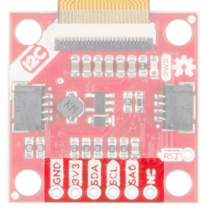
The easiest way to start using the Transparent Graphical OLED is to use a Qwiic Cable along with a Qwiic compatible microcontroller (such as the ESP32 Thing Plus). You can also use the Qwiic Breadboard Cable to attach any I2C capable microcontroller, or take the scenic route and solder in all the I2C wires to the plated-through connections on the board.
So why use I2C? It's easy to connect with the Qwiic system, and you can put up to two of the Transparent Graphical Breakouts on the same bus without using any more microcontroller pins. That simplicity comes at a cost to performance though. The maximum clock speed of the I2C bus is 400 kHz, and there is additional overhead in data transmission to indicate which bytes are data and which are commands. This means that the I2C connection is best for showing static images.
| Breakout Pin | Microcontroller Pin Requirements |
|---|---|
| GND | Ground pin. Connect these so the two devices agree on voltages |
| 3V3 | 3.3V supply pin, capable of up to 400 mA output |
| SDA | SDA - the bi-directional data line of your chosen I2C port |
| SCL | SCL - the clock line of your chosen I2C port |
| SA0 | Optional : change the I2C address of the breakout. Make sure to cut JP2 |
| RST | Optional : reset the breakout to a known state by pulsing this low |
SPI
SPI solves the I2C speed problems. With SPI there is a control signal that indicates data or command and the maximum clock speed is 10 MHz -- giving SPI 50x more speed! However, it doesn't have the same conveniences of the polarized Qwiic connector and low pin usage. You'll need to solder to the pins.
You can use SPI to connect as many breakouts as you want. For N displays you will need to use at least N + 3 data pins. That's because the MOSI, SCLK, and D/C pins can be shared between displays but each breakout needs its own dedicated Chip Select (CS) pin.
| Breakout Pin | Microcontroller Pin Requirements |
|---|---|
| CS | A GPIO pin, set low when talking to the breakout |
| D/C | A GPIO pin, indicates if bytes are data or commands |
| SCLK | The clock output of your chosen SPI port |
| MOSI | The data output of your chosen SPI port |
| 3V3 | 3.3V supply pin, capable of up to 400 mA output |
| GND | Ground pin. Connect these so the two devices agree on voltages |
Warning
Make sure to cut jumpers JP1, JP2, JP3, and JP4 when using SPI mode!
Software
The Transparent OLED Breakout (Qwiic) uses the SparkFun QWIIC OLED Arduino Library. The SparkFun Qwiic OLED library Getting Started guide has library setup instructions and usage examples. Additionally, the full library API documentation is available in the SparkFun Qwiic OLED Library API Reference guide.
Resources
For more information on the Transparent Graphical OLED Breakout, check out some of the links here:
Qwiic OLED (0.91", 128x32)
Introduction
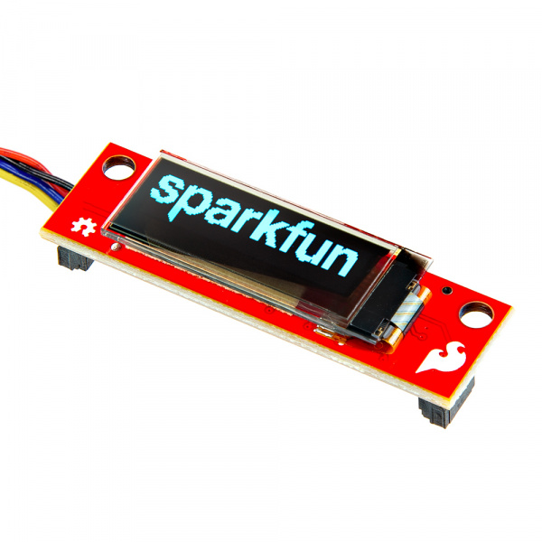
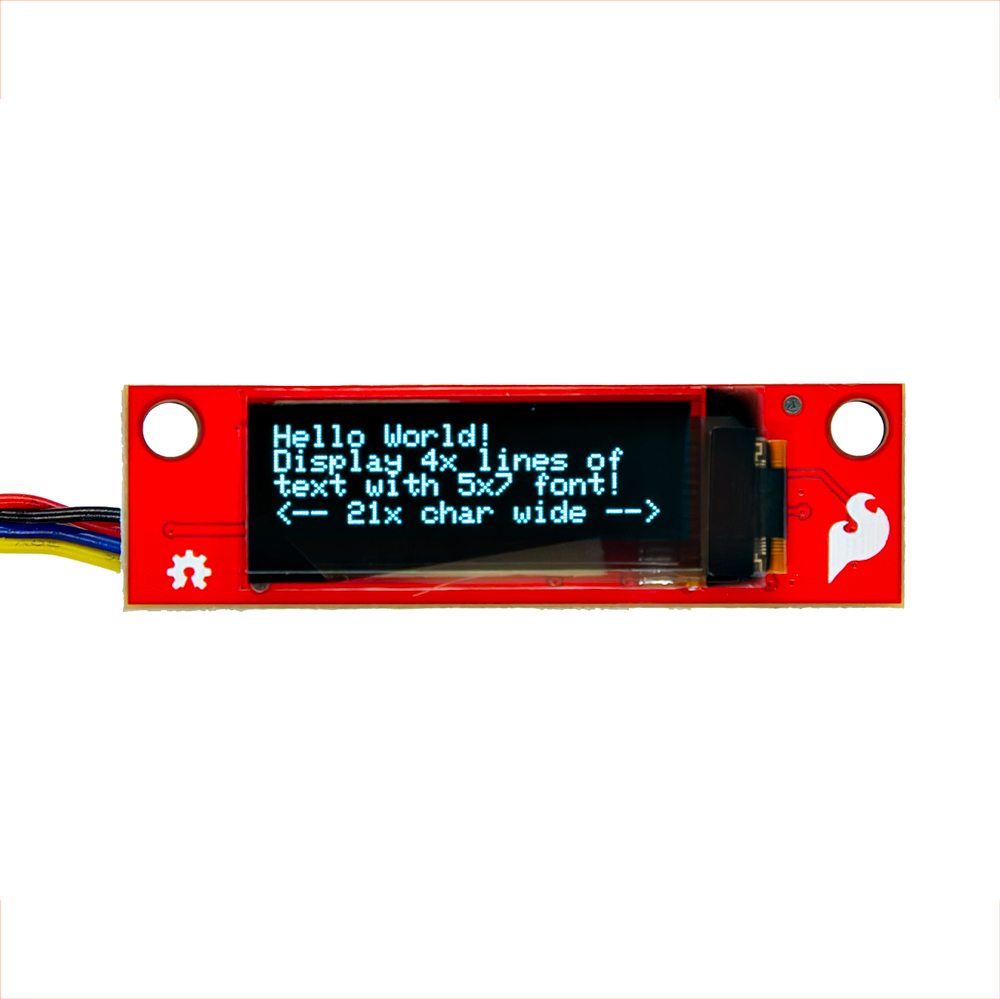
The SparkFun Qwiic OLED Display can display up to four lines of text and features 128x32 pixels in a small 0.91” (diagonal) frame. As an OLED, this display does not have a back light layer (unlike LCDs) and therefore it’s thinner, consumes less power, and has higher contrast.
In this section, we'll go over the hardware and how to hookup the breakout board.
Required Materials
To follow along with this tutorial, you will need the following materials. You may not need everything though depending on what you have. Add it to your cart, read through the guide, and adjust the cart as necessary.
- 1x SparkFun RedBoard Plus [DEV-18158]
- 1x Reversible USB A to C Cable - 0.8m [CAB-15425]
- 1x Qwiic Cable
- Flexible Qwiic Cable - 50mm [PRT-17260], for short distances
- Flexible Qwiic Cable - 500mm [PRT-17257], for those that need to wire the board farther away from your microcontroller
- 1x SparkFun Qwiic OLED Display (0.91 in., 128x32) [LCD-22495]
Microcontroller
To get started, you'll need a microcontroller to, well, control everything. We used the RedBoard with the ATmega328P for the Qwiic micro OLED. However, any of the other microcontrollers that are compatible with the Qwiic OLED Arduino Library will work as well. Below are a few from the list that we provided earlier.
USB Cable
Below are a few USB cables from the SparkFun catalog. Make sure to grab the associated USB cable that is compatible with your microcontroller.
Qwiic
If the controller you choose doesn't have a built-in Qwiic connector, one of the following Qwiic shields that matches your preference of microcontroller is needed:
You will also need a Qwiic cable to connect the shield to your OLED, choose a length that suits your needs.
Of course, you will also need a Qwiic Micro OLED if you have not added that to you cart already.
Hardware Overview
In this section, we will highlight the hardware and pins that are broken out on the SparkFun Qwiic OLED Display (0.91 in., 128x32).
OLED Display (0.91", 128x32)
The OLED screen has a pixel resolution of 128x32, a panel size of 30.0mm x 11.5mm x 1.2mm, and an active area of 22.384mm x 5.584mm. The driver chip is the SSD1306. For information can be found in the datasheet linked in the Resources.
Note
The SparkFun Qwiic OLED Arduino Library works for multiple displays. However, there are some caveats in the size of the display with the text. While you can technically display all fonts in the narrow OLED display, some characters (numbers, letters, and/or symbols depending on the font) will be too big to fully display on the screen. For example, the fonts for the 31x48 (i.e. &QW_FONT_31X48) and large numbers (i.e. &QW_FONT_LARGENUM) are too big to fit within the display.
Using the OLED display (0.91", 128x32) we found that we were able to fit:
- 4x lines, 21x characters using the 5x7 (i.e.
&QW_FONT_5X7) - 2x lines, 14x characters using the 8x16 (i.e.
&QW_FONT_8X16) - 2x lines, 11x characters using the 7 segment (i.e.
&QW_FONT_7SEGMENT)
Power
Power is applied through the vertical Qwiic connectors on the back of the board. The recommended input voltage is 3.3V. The logic levels for the Qwiic OLED Display (0.9", 128x32) is 3.3V.
Qwiic and I2C
There are two vertical Qwiic connectors populated on the back of the board. You can use either connectors to provide power and send data through I2C. The Qwiic ecosystem is made for fast prototyping by removing the need for soldering. All you need to do is plug a Qwiic cable into the Qwiic connector and voila!
- SCL — I2C clock
- SDA — I2C data
- 3.3V — Power
- GND — Ground
The address of the display is 0x3C.
Note
On the back of the board, the power and I2C pins are broken out to test points. These are used in our production department for quality control using custom testbeds. These could be an alternative option to connect to the pins. However, we recommend using the Qwiic connectors to easily connect to the OLED display. Note that the I2C pins are also in a different order compared to a standard I2C Qwiic connector should you decide to solder to the test points.
Jumpers
Note
If this is your first time working with jumpers, check out the How to Work with Jumper Pads and PCB Traces tutorial for more information.
The board includes a 1x3 jumper on the back of the board.
- I2C — This three way jumper labeled I2C is connected to two 4.7kΩ pull-up resistors to the I2C data and clock lines. For users that have multiple Qwiic-enabled devices with pull-up resistors enabled, the parallel equivalent resistance will create too strong of a pull-up for the bus to operate correctly. As a general rule of thumb, disable all but one pair of pull-up resistors if multiple devices are connected to the bus.
Board Dimensions
Version 1.1 is a bit smaller than previous versions since the board includes vertical Qwiic connectors on the back of the board. The overall board size is 1.75 in x 0.5 in. The mounting holes have also moved to toward the top of the board.
Hardware Hookup
In this section, we'll go over how to connect to the display. We will go just a bit further and talk about how to mount the display.
Connecting via Qwiic Connector
Insert a Qwiic cable between your chosen microcontroller and Qwiic OLED. Then insert a USB cable between the microcontroller and your computer's COM port. For the scope of this tutorial, the USB cable provides power and allows us to upload code to the microcontroller. Of course, you can also debug the display by opening a Serial Terminal.
Once you have finished prototyping, you could continue to use the USB cable and add a 5V power supply or battery pack.
Mounting the Qwiic OLED (0.9", 128x32)
Grab the board dimensions and cut out a rectangle in the enclosure. For users that want to mount the board so that the OLED display is flush against the enclosure, you will need to look at the dimensions based on the OLED. You will need to add a little tolerance so that the display can fit through the rectangle. For users that need to quickly mount the board, you will could also cut out rectangles based on the vertical Qwiic connector so that the wires can lead into the enclosure. Then cut out the mounting holes so that the board is right side up. In this case, we used a cardboard box as a quick example to demonstrate the Qwiic wires connecting leading into the enclosure.
Note
To easily display text and graphics on the board, we recommend mounting the board right side up. There is an option in the example code to flip the text horizontally and vertically should you decide to mount the board upside down, but you would need to also determine the position of the text.
For a more durable enclosure, you could use wood, metal, or plastic. However, you will need additional tools to cut into the material.
Software
The Qwiic OLED (0.91", 128x32) uses the SparkFun QWIIC OLED Arduino Library. The SparkFun Qwiic OLED Library's Software Setup has instructions and usage examples. Additionally, the full library API documentation is available in the SparkFun Qwiic OLED Library API Reference guide.
Resources
Now that you've successfully got your OLED Display (0.9", 128x36) up and running, it's time to incorporate it into your own project! For more information, check out the resources below:
- Schematic (PDF)
- Eagle Files (ZIP)
- Board Dimensions (PNG)
- Datasheet (PDF) (0.91", 128x32, SSD1306)
- ReadtheDocs: Qwiic_OLED_Display_Py
- Qwiic OLED Display Python Package Repo
- Github Hardware Repo
Qwiic OLED (1.3", 128x64)
The Qwiic OLED 1.3in has its own hook-up guide.
Software Setup
Software Setup
Installation
Arduino
This guide assumes you are using the latest version of the Arduino IDE on your desktop. The following resources available at SparkFun provide the details on setting up and configuring Arduino to use this library.
The SparkFun Qwiic OLED Arduino Library is available within in the Arduino library manager, which is launched via the Sketch > Include Libraries > Manage Libraries … menu option in the Arduino IDE. Just search for SparkFun Qwiic OLED Library.
Note
If you've never connected a USB-to-serial converter to your computer before, you may need to install drivers. The drivers will depend on what is populated on your Arduino development board. Check out the following tutorials for help with the installation.
General Use Pattern
After installing this library in your local Arduino environment, begin with a standard Arduino sketch, and include the header file for this library.
The next step is to declare the object for the SparkFun qwiic OLED device used. Like most Arduino sketches, this is done at a global scope (after the include file declaration), not within the setup() or loop() functions.
The user selects from one of the following classes:
| Class | Qwiic OLED Device |
|---|---|
QwiicMicroOLED |
SparkFun Qwiic Micro OLED |
QwiicNarrowOLED |
SparkFun Qwiic OLED Display (128x32) |
QwiicTransparentOLED |
SparkFun Transparent Graphical OLED |
Qwiic1in3OLED |
SparkFun Qwiic OLED 1.3" Display (128x32) |
For this example, the Qwiic Micro OLED is used.
In the setup() function of this sketch, like all of the SparkFun qwiic libraries, the device is initialized by calling the begin() method. This method returns a value of true on success, or false on failure.
int width, height;  // global variables for use in the sketch
void setup()
{
    Serial.begin(115200);
    if(!myOLED.begin()){
        Serial.println("Device failed to initialize");
        while(1);  // halt execution
    }
    Serial.println("Device is initialized");

}
Now that the library is initialized, the desired graphics are drawn. Here we erase the screen and draw simple series of lines that originate at the screen origin and fan out across the height of the display.
Note
Graphics are not send to the OLED device when drawn. Updates are only sent to the device when the display() method is called. This minimizes data transfers to the OLED device, delivering a responsive display response.
    myOLED.erase();           // Erase the screen
    myOLED.display();         // Send erase to device

    delay(1000);    // Slight pause

    // Draw our lines from point (0,0) to (i, screen height)

    for(int i=0; i < width; i+= 6){
        myOLED.line(0, 0, i, height-1);    // draw the line
        myOLED.display();                  // Send the new line to the device for display
    }
Library Provided Examples
The SparkFun Qwiic OLED Arduino Library, includes a wide variety of examples. These are available from the Examples menu of the Arduino IDE, and in the examplesfolder of this repository.
For a detailed description of the examples, see the Examples section of the documentation.
API Reference
Device
Device Operations
Methods to setup the device, get device information and change display options.
Initialization
begin()
This method is called to initialize the OLED library and connection to the OLED device. This method must be called before calling any graphics methods.
| Parameter | Type | Description |
|---|---|---|
wirePort |
TwoWire |
optional. The Wire port. If not provided, the default port is used |
address |
uint8_t |
optional. I2C Address. If not provided, the default address is used. |
| return value | bool |
true on success, false on startup failure |
reset()
When called, this method reset the library state and OLED device to their intial state. Helpful to reset the OLED after waking up a system from a sleep state.
| Parameter | Type | Description |
|---|---|---|
| return value | bool |
true on success, false on startup failure |
Geometry
getWidth()
This method returns the width, in pixels, of the connected OLED device
| Parameter | Type | Description |
|---|---|---|
| return value | uint8_t |
The width in pixels of the connected OLED device |
getHeight()
This method returns the height, in pixels, of the connected OLED device
| Parameter | Type | Description |
|---|---|---|
| return value | uint8_t |
The height in pixels of the connected OLED device |
Display Modes
invert()
This method inverts the current graphics on the display. This results of this command happen immediatly.
| Parameter | Type | Description |
|---|---|---|
bInvert |
bool |
true - the screen is inverted. false - the screen is set to normal |
flipVertical()
When called, the screen contents are flipped vertically if the flip parameter is true, or restored to normal display if the flip parameter is false.
| Parameter | Type | Description |
|---|---|---|
bFlip |
bool |
true - the screen is flipped vertically. false - the screen is set to normal |
flipHorizontal()
When called, the screen contents are flipped horizontally if the flip parameter is true, or restored to normal display if the flip parameter is false.
| Parameter | Type | Description |
|---|---|---|
bFlip |
bool |
true - the screen is flipped horizontally. false - the screen is set to normal |
displayPower()
Used to turn the OLED display on or off.
| Parameter | Type | Description |
|---|---|---|
bEnable |
bool |
true - the OLED display is powered on (default). false - the OLED dsiplay is powered off. |
Scrolling
Scrolling
Methods for device scrolling
scrollStop()
If the device is in a scrolling mode, calling this method stops the scroll, and restores the device to normal display operation. This action is performed immediately.
| Parameter | Type | Description |
|---|---|---|
| NONE |
scrollRight()
This method is called to start the device scrolling the displayed graphics to the right. This action is performed immediately.
The screen will scroll until the scrollStop() method is called.
| Parameter | Type | Description |
|---|---|---|
start |
uint8_t |
The start page address of the scroll - valid values are 0 thru 7 |
stop |
uint8_t |
The stop/end page address of the scroll - valid values are 0 thru 7 |
interval |
uint8_t |
The time interval between scroll step - values listed below |
Defined values for the interval parameter:
| Defined Symbol | Time Interval Between Steps |
|---|---|
SCROLL_INTERVAL_2_FRAMES |
2 |
SCROLL_INTERVAL_3_FRAMES |
3 |
SCROLL_INTERVAL_4_FRAMES |
4 |
SCROLL_INTERVAL_5_FRAMES |
5 |
SCROLL_INTERVAL_25_FRAMES |
25 |
SCROLL_INTERVAL_64_FRAMES |
64 |
SCROLL_INTERVAL_128_FRAMES |
128 |
SCROLL_INTERVAL_256_FRAMES |
256 |
scrollVertRight()
This method is called to start the device scrolling the displayed graphics vertically and to the right. This action is performed immediately.
The screen will scroll until the scrollStop() method is called.
| Parameter | Type | Description |
|---|---|---|
start |
uint8_t |
The start page address of the scroll - valid values are 0 thru 7 |
stop |
uint8_t |
The stop/end page address of the scroll - valid values are 0 thru 7 |
interval |
uint8_t |
The time interval between scroll step - values listed in scrollRight |
scrollLeft()
This method is called start to the device scrolling the displayed graphics to the left. This action is performed immediately.
The screen will scroll until the scrollStop() method is called.
| Parameter | Type | Description |
|---|---|---|
start |
uint8_t |
The start page address of the scroll - valid values are 0 thru 7 |
stop |
uint8_t |
The stop/end page address of the scroll - valid values are 0 thru 7 |
interval |
uint8_t |
The time interval between scroll step - values listed in scrollRight |
scrollVertLeft()
This method is called to start the device scrolling the displayed graphics vertically and to the left. This action is performed immediately.
The screen will scroll until the scrollStop() method is called.
| Parameter | Type | Description |
|---|---|---|
start |
uint8_t |
The start page address of the scroll - valid values are 0 thru 7 |
stop |
uint8_t |
The stop/end page address of the scroll - valid values are 0 thru 7 |
interval |
uint8_t |
The time interval between scroll step - values listed in scrollRight |
Drawing State
Drawing Settings/State
Methods for setting the drawing state of the library.
setFont()
This method is called to set the current font in the library. The current font is used when calling the text() method on this device.
The default font for the device is 5x7.
| Parameter | Type | Description |
|---|---|---|
theFont |
QwiicFont |
The font to set as current in the device |
theFont |
QwiicFont* |
Pointer to the font to set as current in the device. |
For the library, fonts are added to your program by including them via include files which are part of this library.
The following fonts are included:
| Font | Include File | Font Variable | Description |
|---|---|---|---|
| 5x7 | <res/qw_fnt_5x7.h> |
QW_FONT_5X7 |
A full, 5 x 7 font |
| 31x48 | <res/qw_fnt_31x48.h> |
QW_FONT_31X48 |
A full, 31 x 48 font |
| Seven Segment | <res/qw_fnt_7segment.h> |
QW_FONT_7SEGMENT |
Numbers only |
| 8x16 | <res/qw_fnt_8x16.h> |
QW_FONT_8X16 |
A full, 8 x 16 font |
| Large Numbers | <res/qw_fnt_largenum.h> |
QW_FONT_LARGENUM |
Numbers only |
For each font, the font variables are objects with the following attributes:
| Attribute | Value |
|---|---|
width |
The font width in pixels |
height |
The font height in pixels |
start |
The font start character offset |
n_chars |
The number of characters |
map_width |
The width of the font map |
Example use of a font object attribute:
getFont()
This method returns the current font for the device.
| Parameter | Type | Description |
|---|---|---|
| return value | QwiicFont* |
A pointer to the current font. See setFont() for font object details. |
getFontName()
This method returns the height in pixels of a provided String based on the current device font.
| Parameter | Type | Description |
|---|---|---|
| return value | String | The name of the current font. |
getStringWidth()
This method returns the width in pixels of a provided String based on the current device font.
| Parameter | Type | Description |
|---|---|---|
| text | String |
The string used to determine width |
| return value | unsigned int |
The width of the provide string, as determined using the current font. |
getStringHeight()
This method returns the height in pixels of a provided String based on the current device font.
| Parameter | Type | Description |
|---|---|---|
| text | String |
The string used to determine height |
| return value | unsigned int |
The height of the provide string, as determined using the current font. |
setDrawMode()
This method sets the current draw mode for the library. The draw mode determines how pixels are set on the screen during drawing operations.
| Parameter | Type | Description |
|---|---|---|
| rop | grRasterOp_t |
The raster operation (ROP) to set the graphics system to. |
Raster operations device how source (pixels to draw) are represented on the destination device. The available Raster Operation (ROP) codes are:
| ROP Code | Description |
|---|---|
| grROPCopy | default Drawn pixel values are copied to the device screen |
| grROPNotCopy | A not operation is applied to the source value before copying to screen |
| grROPNot | A not operation is applied to the destination (screen) value |
| grROPXOR | A XOR operation is performed between the source and destination values |
| grROPBlack | A value of 0, or black is drawn to the destination |
| grROPWhite | A value of 1, or black is drawn to the destination |
getDrawMode()
This method returns the current draw mode for the library. The draw mode determines how pixels are set on the screen during drawing operations.
| Parameter | Type | Description |
|---|---|---|
| return value | grRasterOp_t |
The current aster operation (ROP) of the graphics system. |
Graphics
Graphics Methods
Methods used to draw and display graphics.
display()
When called, any pending display updates are sent to the connected OLED device. This includes drawn graphics and erase commands.
| Parameter | Type | Description |
|---|---|---|
| NONE |
erase()
Erases all graphics on the device, placing the display in a blank state. The erase update isn't sent to the device until the next display() call on the device.
| Parameter | Type | Description |
|---|---|---|
| NONE |
pixel()
Set the value of a pixel on the screen.
| Parameter | Type | Description |
|---|---|---|
| x | uint8_t |
The X coordinate of the pixel to set |
| y | uint8_t |
The Y coordinate of the pixel to set |
| clr | uint8_t |
optional The color value to set the pixel. This defaults to white (1). |
line()
Draw a line on the screen.
Note: If a line is horizontal (y0 = y1) or vertical (x0 = x1), optimized draw algorithms are used by the library.
| Parameter | Type | Description |
|---|---|---|
| x0 | uint8_t |
The start X coordinate of the line |
| y0 | uint8_t |
The start Y coordinate of the line |
| x1 | uint8_t |
The end X coordinate of the line |
| y1 | uint8_t |
The end Y coordinate of the line |
| clr | uint8_t |
optional The color value to draw the line. This defaults to white (1). |
rectangle()
Draw a rectangle on the screen.
| Parameter | Type | Description |
|---|---|---|
| x0 | uint8_t |
The start X coordinate of the rectangle - upper left corner |
| y0 | uint8_t |
The start Y coordinate of the rectangle - upper left corner |
| width | uint8_t |
The width of the rectangle |
| height | uint8_t |
The height of the rectangle |
| clr | uint8_t |
optional The color value to draw the line. This defaults to white (1). |
rectangleFill()
Draw a filled rectangle on the screen.
| Parameter | Type | Description |
|---|---|---|
| x0 | uint8_t |
The start X coordinate of the rectangle - upper left corner |
| y0 | uint8_t |
The start Y coordinate of the rectangle - upper left corner |
| width | uint8_t |
The width of the rectangle |
| height | uint8_t |
The height of the rectangle |
| clr | uint8_t |
optional The color value to draw the line. This defaults to white (1). |
circle()
Draw a circle on the screen.
| Parameter | Type | Description |
|---|---|---|
| x0 | uint8_t |
The X coordinate of the circle center |
| y0 | uint8_t |
The Y coordinate of the circle center |
| radius | uint8_t |
The radius of the circle |
| clr | uint8_t |
optional The color value to draw the circle. This defaults to white (1). |
circleFill()
Draw a filled circle on the screen.
| Parameter | Type | Description |
|---|---|---|
| x0 | uint8_t |
The X coordinate of the circle center |
| y0 | uint8_t |
The Y coordinate of the circle center |
| radius | uint8_t |
The radius of the circle |
| clr | uint8_t |
optional The color value to draw the circle. This defaults to white (1). |
bitmap()
Draws a bitmap on the screen.
The bitmap should be 8 bit encoded - each pixel contains 8 y values.
| Parameter | Type | Description |
|---|---|---|
| x0 | uint8_t |
The X coordinate to place the bitmap - upper left corner |
| y0 | uint8_t |
The Y coordinate to place the bitmap - upper left corner |
| pBitmap | uint8_t * |
A pointer to the bitmap array |
| bmp_width | uint8_t |
The width of the bitmap |
| bmp_height | uint8_t |
The height of the bitmap |
bitmap()
Draws a bitmap on the screen.
The bitmap should be 8 bit encoded - each pixel contains 8 y values.
The coordinate [x1,y1] allows for only a portion of bitmap to be drawn.
void bitmap(uint8_t x0, uint8_t y0, uint8_t x1, uint8_t y1,
                uint8_t *pBitmap, uint8_t bmp_width, uint8_t bmp_height )
| Parameter | Type | Description |
|---|---|---|
| x0 | uint8_t |
The X coordinate to place the bitmap - upper left corner |
| y0 | uint8_t |
The Y coordinate to place the bitmap - upper left corner |
| x1 | uint8_t |
The end X coordinate of the bitmap - lower right corner |
| y1 | uint8_t |
The end Y coordinate of the bitmap - lower right corner |
| pBitmap | uint8_t * |
A pointer to the bitmap array |
| bmp_width | uint8_t |
The width of the bitmap |
| bmp_height | uint8_t |
The height of the bitmap |
bitmap()
Draws a bitmap on the screen using a Bitmap object for the bitmap data.
| Parameter | Type | Description |
|---|---|---|
| x0 | uint8_t |
The X coordinate to place the bitmap - upper left corner |
| y0 | uint8_t |
The Y coordinate to place the bitmap - upper left corner |
| Bitmap | QwiicBitmap |
A bitmap object |
text()
Draws a string using the current font on the screen.
| Parameter | Type | Description |
|---|---|---|
| x0 | uint8_t |
The X coordinate to start drawing the text |
| y0 | uint8_t |
The Y coordinate to start drawing the text |
| text | const char* |
The string to draw on the screen |
| text | String |
The Arduino string to draw on the screen |
| clr | uint8_t |
optional The color value to draw the circle. This defaults to white (1). |
Arduino Print
Arduino Print
Methods used to support Arduino Print functionality.
setCursor()
This method is called set the "cursor" position in the device. The library supports the Arduino Print interface, enabling the use of a print() and println() methods. The set cursor position defines where to start text output for this functionality.
| Parameter | Type | Description |
|---|---|---|
| x | uint8_t |
The X coordinate of the cursor |
| y | uint8_t |
The Y coordinate of the cursor |
setColor()
This method is called to set the current color of the system. This is used by the Arduino Print interface functionality
| Parameter | Type | Description |
|---|---|---|
clr |
uint8_t |
The color to set. 0 = black, > 0 = white |
getColor()
This method is called to get the current color of the system. This is used by the Arduino Print interface functionality
| Parameter | Type | Description |
|---|---|---|
| return value | uint8_t |
The current color |
Arduino Examples
Example 1 - Hello
--8<-- "./docs/ex_01_hello.md
Example 2 - Shapes
--8<-- "./docs/ex_02_lines.md
Example 3 - Bitmaps
--8<-- "./docs/ex_03_bitmaps.md
Example 4 - Text
--8<-- "./docs/ex_04_text.md
Other Examples
--8<-- "./docs/ex_other.md
Troubleshooting
General Troubleshooting Help
Note
Not working as expected and need help?
If you need technical assistance and more information on a product that is not working as you expected, we recommend heading on over to the SparkFun Technical Assistance page for some initial troubleshooting.
If you don't find what you need there, the SparkFun Forums are a great place to find and ask for help. If this is your first visit, you'll need to create a Forum Account to search product forums and post questions.
