Introduction
-
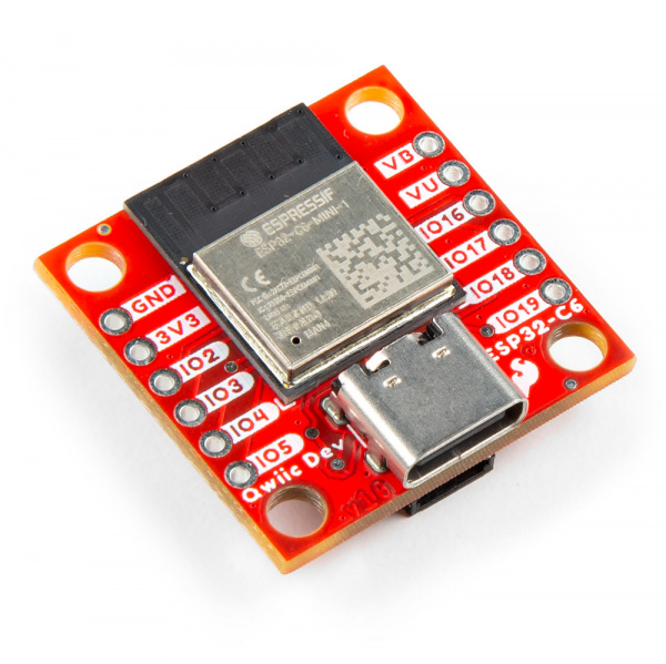
SparkFun Qwiic Pocket Development Board - ESP32-C6
SKU: DEV-22925
-
The SparkFun Qwiic Pocket Development Board - ESP32-C6features the ESP32-C6 Mini-1 module from espressif™. The ESP32-C6 SoC is built around a RISC-V single-core processor with 4 MB flash memory and supports 2.4 GHz WiFi 6, Bluetooth® 5 (with Low Energy), Zigbee and Thread 802.15.4 wireless protocols. The module uses an integrated PCB antenna.
The ESP32-C6 includes on-chip serial-to-UART conversion which helps reduce the number of components on the development board so we designed this Qwiic Dev Board to cram as much as we could into the Qwiic system's 1"x1" form factor. It also includes a USB-C connector, 2-pin JST connector for a single-cell LiPo battery along with a charging circuit for a connected battery, a Qwiic connector, and it also breaks out eight GPIO pins (including one UART).Purchase from SparkFun
Required Materials
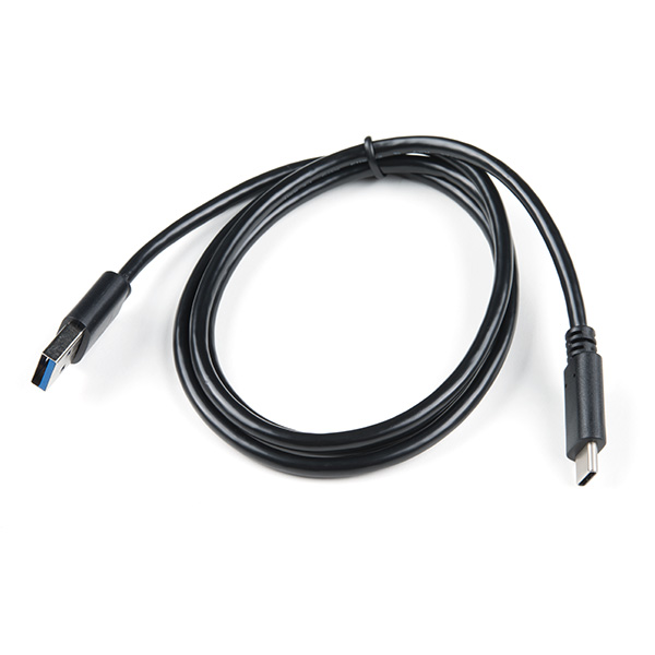
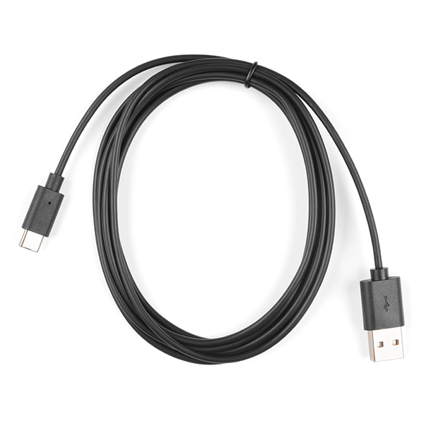
To follow along with this guide you will need a USB-C cable to connect the dev board to your computer:
You may also want to get a Qwiic cable or kit to connect the Qwiic Dev Board - ESP32-C6 to other Qwiic devices:
Optional Materials
The Qwiic Dev Board - ESP32-C6 includes a 2-pin JST connector and integrated charging circuit for an attached single-cell LiPo battery. Below are a few options for batteries we recommend for battery-powered applications:


If you prefer a soldered connection or want to modify the solder jumpers on this board, you may need some of the products listed below:
Smart Watch Example Materials
This guide also includes a demo using the Qwiic Pocket Development Board - ESP32-C6 with three Qwiic breakouts to create a DIY "smart watch" (sans the wristband) complete with display, pedometer, and motion controls. If you'd like to follow along and build this example, you'll need the following Qwiic breakouts:
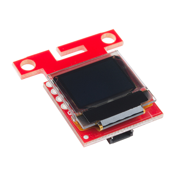
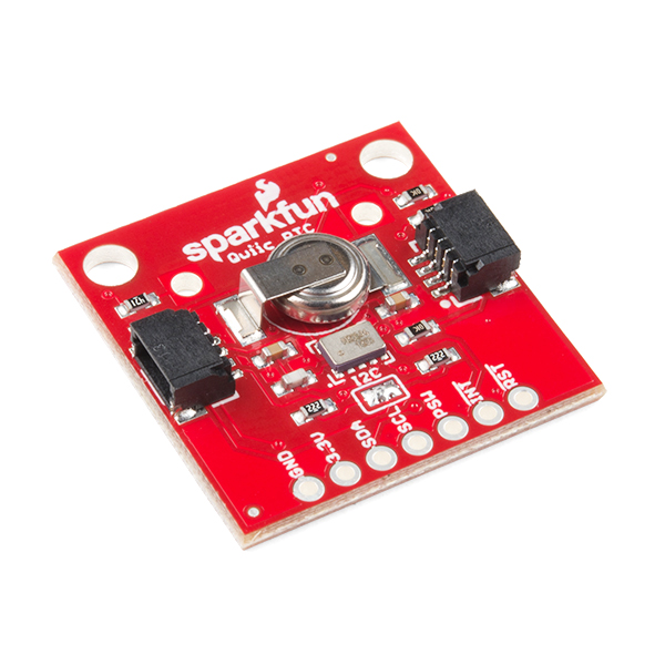
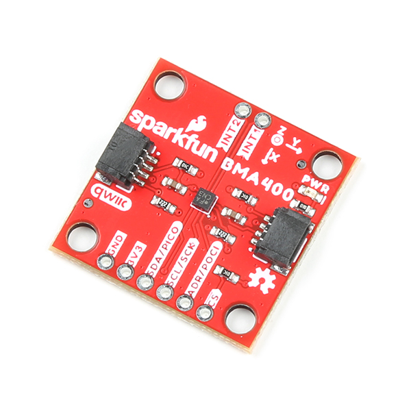
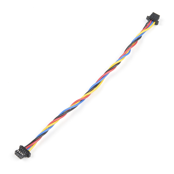
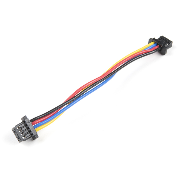
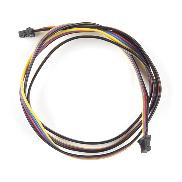
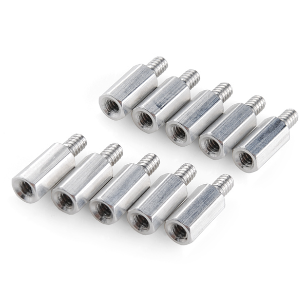
You'll also need three Qwiic cables of your choice of length and a set of standoffs to assemble the smart watch. We recommend either the 50mm or 100mm flexible cables as shown below:


Suggested Reading
We designed this board for integration into SparkFun's Qwiic connect system. Click on the banner below to learn more about the SparkFun Qwiic Connect System.

Before getting started with this Hookup Guide, you may want to read through the tutorials below if you are not familiar with the concepts covered in them or want a refresher. If you are using either of the Qwiic Shields linked above, we recommend reading through their respective Hookup Guides before continuing with this tutorial:


Hardware Overview
Let's take a closer look at the ESP32-C6 module and other hardware on the Qwiic Pocket Development Board.
ESP32-C6 Mini-1 Module
The ESP32-C6 Mini-1 module from espressif features a 32-bit RISC-V single-core processor with an integrated wireless stack. The wireless stack is compatible with 2.4 GHz WiFi 6, Bluetooth® 5.3, Zigbee and Thread (802.15.4) and uses an on-board PCB antenna.

This development board uses the Mini version of the C6 module which has slightly less computing power in exchange for greater power efficiency. This makes this module perfect for battery-powered applications. The module features a wide range of peripheral options including SPI, UART, LPUART, I2C, I2S, LED PWM, USB Serial/JTAG controller, ADC and more. Many of these peripherals can be mapped to any GPIO pin though some are tied to specific pins. Refer to the datasheet for a complete overview of the ESP32-C6-MINI-1.
The ESP32-C6 has 4 MB Flash memory along with 512 KB SRAM (high power)/ 16 KB SRAM (low power). The module uses pin strapping to configure boot mode parameters. The board defaults to standard mode (GPIO 9 internal pull-up, all other strapping pins floating) but it can be set to other parameters by performing the following pin strapping:
- SDIO Sampling and Driving Clock Edge - MTMS & MTDI
- Chip Boot Mode - GPIO8 & GPIO9
- ROM Code Printing to UART - GPIO8
- JTAG Signal Source - GPIO15
Power Components
USB-C Connector
The USB-C connector on the board acts as the primary serial interface for the ESP32-C6 module as well as a power input. It connects directly to the ESP32-C6's USB serial converter. The 5V USB input voltage is regulated down to 3.3V through a voltage regulator with a max current of 500mA@3.3V.

JST Connector & Battery Charger
The board has a 2-pin JST connector to connect a single-cell Lithium Ion (LiPo) battery for battery-powered applications. It also has an MCP73831 battery charger to charge an attached battery. The charge rate is set to 214mA@3.3V. The MCP73831 receives power from the V_USB line so it only is powered when 5V is provided either over USB or the V_USB PTH pin. If applying voltage directly to the V_USB pin make sure it does not exceed 5.5V.

Pinout & Qwiic Connector
PTH Pins
The Qwiic Dev Board routes eight GPIO pins to a pair of 0.1"-spaced PTH headers. One side has 3.3V and GND pins along with I/O pins 2, 3, 4, and 5. The other side has through-holes for V_USB and VBatt as well as I/O pins 16 (TX), 17 (RX), 18, and 19.

Qwiic Connector
There's a Qwiic connector on the board tied to the ESP32-C6's Low Power I2C bus (I/O pins 6 and 7) for easy integration into SparkFun's Qwiic ecosystem. The Qwiic connector provides connections for SDA, SCL, 3.3V, and Ground.

Buttons
There are two buttons on the board labeled RESET and BOOT. The RESET button is tied to the ESP32-C6's Enable (EN) pin and resets the module when pressed. The BOOT button puts the ESP32-C6 into bootloader mode when held down during power on or reset.

LEDs
The board has three LEDs labeled PWR, STAT, and CHG. The red Power (PWR) LED indicates whenever the 3.3V circuit is powered. The blue Status (STAT) LED is tied to IO23 on the ESP32. The yellow Charge (CHG) LED indicates whenever the MCP73831 is charging a connected LiPo battery.

Solder Jumpers
There are four solder jumpers on the Qwiic Dev Board labeled CHG, I2C, SHLD, and PWR. The table below outlines the jumpers' labels, default state, function, and any notes regarding their use:

| Label | Default State | Function | Notes |
|---|---|---|---|
| CHG | CLOSED | Completes Charge LED circuit | Open to disable Charge LED |
| I2C | CLOSED | Pulls the SDA/SCL lines to 3.3V through a pair of 2.2kΩ resistors | Three-way jumper. Open completely to disable pullups |
| SHLD | CLOSED | Ties the USB-C shield pin to the ground plane | Open to isolate USB-C shield pin from the board's ground plane |
| PWR | CLOSED | Completes the Power LED circuit | Open to disable the Power LED |
Board Dimensions
The Qwiic Dev Board - ESP32-C6 matches the 1" x 1" (22.6mm x 22.6mm) Qwiic form factor and has two mounting holes that fit a 4-40 screw.

Hardware Assembly
Basic USB Assembly
Basic assembly of the Qwiic Pocket Development Board only requires a USB-C cable connecting the board to a computer. Just plug the cable into the USB-C connector like the photo below shows and move on to the Software Setup section.
Note
Your computer may not recognize the board as a known USB device if you have not installed the espressif boards package in Arduino and/or installed the espressif IDF.
Battery Assembly
If you prefer a battery-powered application, plug a single-cell LiPo battery into the 2-pin JST connector on the underside of the board like the photo below. Remember, the MCP73831 only charges the battery when V_USB has voltage present either from the USB-C connector or through the V_USB PTH pin.

For tips on the proper use of a LiPo battery and the 2-pin JST connector, please read through our Single Cell LiPo Battery Care tutorial.
Software Setup
Attention
If this is your first time using Arduino, please read through our tutorial on installing the Arduino IDE. If you have not installed an Arduino library before, we recommend you check out our installation guide.
With the Qwiic Pocket Dev Board connected to our computer, it's time to set up the boards package in Arduino.
Installing espressif Arduino Boards
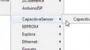
The espressif ESP32 Arduino Boards package includes the Qwiic Pocket Development Board - ESP32-C6. Install it by opening the Boards Manager tab on the left side of the IDE, then search for "espressif ESP32" and install the latest version of the ESP32 boards package as the screenshot below shows. This assumes the use of Arduino 2.x and later. If you're on Legacy Arduino (1.8x and previous) can find the Boards Manager tool in File/Tools/Boards Manager.

espressif IDF
Users who prefer to use espressif's development toolkit, espressif IDF, can get started by following their instructions here and ESP32-C6 specific documentation here.
Arduino Examples
Now that we've installed the espressif boards package in Arduino, it's time to upload our first sketch to make sure everything is working properly.
Example 1 - Blink
This basic example makes sure the board package installed correctly and the board accepts programming properly to blink the blue STAT LED on the board every second. Open the example in Arduino by navigating to File > Examples > Basics > 01-Blink.
USB CDC On Boot Settings
Take note of the option labeled "USB CDC on Boot" when selecting the Board from the Tools menu. This option sets the serial outputs and defines their label for use in code. The SparkFun variants default to Enable USB CDC on boot which sets both Serial and Serial0 as available serial ports. In this configuration, Serial corresponds to the direct USB/Serial converter on the chip (and the USB-C interface) and Serial0 corresponds to the UART0 bus (default pins are 16 and 17).
With either setting, Serial1 is available and refers to the UART1 bus (default pins are 4 and 5).
Select the board (SparkFun ESP32-C6 Qwiic Pocket) and Port and click "Upload". After uploading you should see the STAT LED on the board blinking every second.
Smart Watch Assembly
Building the smart watch with the Pocket Development Board and the three Qwiic breakouts requires a few assembly steps to build the smart watch stack and connect everything using standofs, screws, hookup wire, and Qwiic cables. This assembly also requires a bit of through-hole soldering so if you've never soldered before or would like a refresher, take a look at our How to Solder: Through-Hole Soldering tutorial.
Note
Some users may want to skip ahead and program the Qwiic Pocket Development Board before assembling the smart watch. If you are one of these people, skip ahead to the Software Setup and Smart Watch Example sections to upload the code before building your smart watch stack.
Start by soldering a short length of wire (roughly one inch) to pin 4 on the Pocket Dev Board and then solder the other end to INT1 on the BMA400 Breakout:

Next, stack the BMA400 Breakout on top of the Qwiic Pocket Dev Board using two standoffs and two nuts to secure them to the Qwiic Pocket Dev Board; then connect the two with a Qwiic cable like the photo below show:

Now stack the RTC Breakout on top of those two with a Qwiic cable between the BMA400 and RTC breakouts and finally add the Qwiic OLED on top with a Qwiic cable between this and the RTC breakout. You may want to connect the Qwiic cable to the OLED before securing it into place depending on which connector you opt for as one is a bit of a tough reach once the board is attached. Secure everything in place while being careful not to damage any of the components since the standoffs and other hardware come very close to them.
With the boards stacked and connected together you can plug the battery in at this point, but can also wait until after programming the Pocket Development Board as well. The final assembly should look like the photo below:

Smart Watch Example
Smart Watch Example Libraries
The smart watch demo requires three Arduino libraries for the three Qwiic breakouts used in it. Install the libraries through Arduino's Library Manager Tool by searching for the following: "Micro OLED Breakout", "SparkFun Qwiic RTC RV1805", and "SparkFun BMA400". Users who prefer to install them manually can download ZIP folders of the libraries by clicking the buttons below:
Upload Demo Code
With the Qwiic Pocket Dev Board smart watch assembled, board definitions and libraries installed, we can upload the smart watch code to the Qwiic Pocket Development board. Copy the code below into a blank sketch or you can download it from the GitHub repository.
Smart Watch Demo
// Inlcude libraries needed
#include <Wire.h>
#include "SparkFun_BMA400_Arduino_Library.h"
#include <SparkFun_Qwiic_OLED.h>
#include <SparkFun_RV1805.h>
#include <WiFi.h>
#include "time.h"

// WiFi SSID and password, change these for your WiFi network!
const char* ssid = "your-ssid";
const char* password = "your-password";

// Create RTC object
RV1805 rtc;

// Create OLED object
QwiicMicroOLED oled;

// Create sensor object
BMA400 accelerometer;

// Pin used for button input
int buttonPin = 9;

// Pin used for measuring battery voltage
int batteryPin = 1;

// Pin used for interrupt detection
int interruptPin = 4;

// Flag to know when interrupts occur
volatile bool interruptOccurred = false;

// Flag to know when user input is requested
bool userInput = true;

// Screen index
uint8_t screenIndex = 0;

// Enum to define various screen indices
typedef enum
{
    SCREEN_CLOCK,
    SCREEN_STEP_COUNTER,
    SCREEN_BATTERY_VOLTAGE,
    SCREEN_SYNC_RTC,
    SCREEN_MAX
} screen_index_t;

// Screen size properties
uint8_t midX = 0;
uint8_t midY = 0;
uint8_t clockRadius = 0;
uint8_t rowHeight = 0;

// Screen display flags
volatile bool updateScreen = true;
volatile bool screenOn = true;

// Screen update timer
uint32_t lastUpdateTime = 0;
uint32_t updateInterval = 1000/25;

// Sleep timer to automatically enter deep sleep after inactivity
uint32_t sleepTimerStart = 0;
uint32_t sleepTimerPeriod = 60000;

// Standard time zone relative to GMT (not daylight savings!)
int8_t timeZone = -7;

void setup()
{
    // Start serial
    Serial.begin(115200);
    Serial.println("Watch demo begin!");

    // Configure button pin as input with pullup
    pinMode(buttonPin, INPUT_PULLUP);

    // Configure battery pin as input
    pinMode(batteryPin, INPUT);

    // The ESP32-C6 has an attenuator on the ADC, which defaults to 11dB. This causes the resolution to be reduced
    analogSetAttenuation(ADC_0db);

    // Begin I2C driver
    Wire.begin(6, 7);

    // Begin RTC
    while(!rtc.begin())
    {
        Serial.println("Error: RTC not connected, check wiring and I2C address!");
        delay(1000);
    }
    Serial.println("RTC connected!");

    // Manually set time (uncomment if needed, set current time and upload, then comment out and upload again)
    // rtc.setTime(0,second,minute,hour,day,month,year,weekday);

    // Begin OLED
    while(!oled.begin())
    {
        Serial.println("Error: OLED not connected, check wiring and I2C address!");
        delay(1000);
    }
    Serial.println("OLED connected!");

    // Set screen size parameters
    midX = oled.getWidth() / 2;
    midY = oled.getHeight() / 2;
    clockRadius = min(midX, midY) - 2;
    rowHeight = oled.getHeight() / 3;

    // Begin accelerometer
    while(accelerometer.beginI2C() != BMA400_OK)
    {
        Serial.println("Error: BMA400 not connected, check wiring and I2C address!");
        delay(1000);
    }
    Serial.println("BMA400 connected!");

    // Set up tap detection
    bma400_tap_conf tapConfig =
    {
        .axes_sel = BMA400_TAP_Z_AXIS_EN, // Which axes to evaluate for interrupts (X/Y/Z in any combination)
        .sensitivity = BMA400_TAP_SENSITIVITY_7, // Sensitivity threshold, up to 7 (lower is more sensitive)
        .tics_th = BMA400_TICS_TH_6_DATA_SAMPLES, // Max time between top/bottom peaks of a single tap
        .quiet = BMA400_QUIET_60_DATA_SAMPLES, // Minimum time between taps to trigger interrupt
        .quiet_dt = BMA400_QUIET_DT_4_DATA_SAMPLES, // Minimum time between 2 taps to trigger double tap interrupt
        .int_chan = BMA400_INT_CHANNEL_1 // Which pin to use for interrupts
    };
    accelerometer.setTapInterrupt(&tapConfig);

    // Set up generic 1 interrupt, used to detect when device is rotated away from user
    bma400_gen_int_conf genConfig =
    {
        .gen_int_thres = 125, // 8mg resolution (eg. gen_int_thres=5 results in 40mg)
        .gen_int_dur = 100, // 10ms resolution (eg. gen_int_dur=5 results in 50ms)
        .axes_sel = BMA400_AXIS_XYZ_EN, // Which axes to evaluate for interrupts (X/Y/Z in any combination)
        .data_src = BMA400_DATA_SRC_ACCEL_FILT_LP, // Which filter to use (must be 100Hz, datasheet recommends filter 2)
        .criterion_sel = BMA400_ACTIVITY_INT, // Trigger interrupts when active or inactive
        .evaluate_axes = BMA400_ANY_AXES_INT, // Logical combining of axes for interrupt condition (OR/AND)
        .ref_update = BMA400_UPDATE_MANUAL, // Whether to automatically update reference values
        .hysteresis = BMA400_HYST_96_MG, // Hysteresis acceleration for noise rejection
        .int_thres_ref_x = (uint16_t) -360, // Raw 12-bit acceleration value
        .int_thres_ref_y = 0, // Raw 12-bit acceleration value
        .int_thres_ref_z = 360, // Raw 12-bit acceleration value (at 4g range (default), 512 = 1g)
        .int_chan = BMA400_INT_CHANNEL_1 // Which pin to use for interrupts
    };
    accelerometer.setGeneric1Interrupt(&genConfig);

    // Set up generic 2 interrupt, used to detect when device is rotated towards user
    genConfig.gen_int_thres = 50;
    genConfig.gen_int_dur = 50;
    genConfig.criterion_sel = BMA400_INACTIVITY_INT;
    genConfig.evaluate_axes = BMA400_ALL_AXES_INT;
    accelerometer.setGeneric2Interrupt(&genConfig);

    // Enable step counting
    bma400_step_int_conf stepConfig = {.int_chan = BMA400_INT_CHANNEL_1};
    accelerometer.setStepCounterInterrupt(&stepConfig);

    // Set INT 1 pin as push pull active high
    accelerometer.setInterruptPinMode(BMA400_INT_CHANNEL_1, BMA400_INT_PUSH_PULL_ACTIVE_1);

    // Enable interrupts from accelerometer
    accelerometer.enableInterrupt(BMA400_STEP_COUNTER_INT_EN, true);
    accelerometer.enableInterrupt(BMA400_SINGLE_TAP_INT_EN, true);
    accelerometer.enableInterrupt(BMA400_DOUBLE_TAP_INT_EN, true);
    accelerometer.enableInterrupt(BMA400_GEN1_INT_EN, true);
    accelerometer.enableInterrupt(BMA400_GEN2_INT_EN, true);
    accelerometer.enableInterrupt(BMA400_LATCH_INT_EN, true);

    // Attach interrupt handler
    pinMode(interruptPin, INPUT);
    attachInterrupt(digitalPinToInterrupt(interruptPin), bma400InterruptHandler, RISING);

    // Reset sleep timer
    sleepTimerStart = millis();
}

void loop()
{
    // Check if we need to enter deep sleep
    if((digitalRead(buttonPin) == LOW) || (millis() > (sleepTimerStart + sleepTimerPeriod)))
    {
        enterDeepSleep();
    }

    // Check whether interrupt triggered from accelerometer
    if(interruptOccurred)
    {
        // Reset interrupt flag
        interruptOccurred = false;

        // Reset sleep timer
        sleepTimerStart = millis();

        Serial.print("Interrupt occured: ");

        // Check what the interrupt source was
        uint16_t interruptStatus = 0;
        accelerometer.getInterruptStatus(&interruptStatus);
        if(interruptStatus & BMA400_ASSERTED_S_TAP_INT)
        {
            // Single tap, increment screen index if screen is on
            if(screenOn)
            {
                Serial.println("Single tap");
                screenIndex++;
                updateScreen = true;
            }
        }
        else if(interruptStatus & BMA400_ASSERTED_D_TAP_INT)
        {
            // Double tap used for input within a screen index, if applicable.
            // This always follows a single tap, so decrement screen index and
            // set input flag, if screen is on
            if(screenOn)
            {
                Serial.println("Double tap");
                screenIndex--;
                updateScreen = true;
                userInput = true;
            }
        }
        else if(interruptStatus & BMA400_ASSERTED_GEN1_INT)
        {
            // Generic 1 indicates the device was rotated away from the user, in
            // which case we'll turn the screen off
            Serial.println("Generic 1");
            screenOn = false;
            oled.erase();
            oled.display();

            // The generic interrupts trigger constantly. Disable generic 1, and
            // enable generic 2
            accelerometer.enableInterrupt(BMA400_GEN1_INT_EN, false);
            accelerometer.enableInterrupt(BMA400_GEN2_INT_EN, true);
        }
        else if(interruptStatus & BMA400_ASSERTED_GEN2_INT)
        {
            // Generic 2 indicates the device was rotated towards the user, in
            // which case we'll turn the screen on
            Serial.println("Generic 2");
            screenOn = true;
            updateScreen = true;

            // The generic interrupts trigger constantly. Disable generic 2, and
            // enable generic 1
            accelerometer.enableInterrupt(BMA400_GEN1_INT_EN, true);
            accelerometer.enableInterrupt(BMA400_GEN2_INT_EN, false);
        }
        else if(interruptStatus & BMA400_ASSERTED_STEP_INT)
        {
            // Step counter incremented, update the screen to give live count
            Serial.println("Step");
            updateScreen = true;
        }
        else
        {
            // Unknown source, just print and ignore it
            Serial.println("Unknown interrupt");
            Serial.println(interruptStatus, HEX);
        }
    }

    // Figure out what to display on the screen, if anything
    if(screenOn)
    {
        screenIndex %= SCREEN_MAX;
        switch(screenIndex)
        {
            case SCREEN_CLOCK:
                displayClock();
                break;
            case SCREEN_STEP_COUNTER:
                displayStepCounter();
                break;
            case SCREEN_BATTERY_VOLTAGE:
                displayBatteryVoltage();
                break;
            case SCREEN_SYNC_RTC:
                displaySyncRTC();
                break;
            default:
                // Shouldn't get here, but just in case
                screenIndex = 0;
                break;
        }
    }

    // Reset flags
    userInput = false;
}

// Displays time an analog clock style
void displayClock()
{
    // Check if we need to update the screen. Uses a timer to limit refresh rate
    if(!updateScreen)
    {
        if(millis() >= (lastUpdateTime + updateInterval))
        {
            lastUpdateTime += updateInterval;
        }
        else
        {
            return;
        }
    }
    updateScreen = false;

    // Get current time from RTC
    rtc.updateTime();
    int timeMilli = millis() % 1000;
    int timeSecs = rtc.getSeconds();
    int timeMins = rtc.getMinutes();
    int timeHours = rtc.getHours() % 12;

    // Clear OLED
    oled.erase();

    // Draw circle to define clock face
    oled.circle(midX, midY, clockRadius);

    // Draw a solid circle to indicate 1 second intervals
    int x = (clockRadius+1) * sin(timeMilli * 2*PI/1000);
    int y = (clockRadius+1) *-cos(timeMilli * 2*PI/1000);
    oled.circleFill(midX + x, midY + y, 2);

    // Draw second hand
    x = clockRadius * sin(timeSecs * 2*PI/60);
    y = clockRadius *-cos(timeSecs * 2*PI/60);
    oled.line(midX, midY, midX + x, midY + y);

    // Draw minute hand
    x = clockRadius*.75 * sin(timeMins * 2*PI/60);
    y = clockRadius*.75 *-cos(timeMins * 2*PI/60);
    oled.line(midX, midY, midX + x, midY + y);

    // Draw hour hand
    x = clockRadius*.5 * sin(timeHours * 2*PI/12);
    y = clockRadius*.5 *-cos(timeHours * 2*PI/12);
    oled.line(midX, midY, midX + x, midY + y);

    // Display on the OLED
    oled.display();
}

// Displays step count
void displayStepCounter()
{
    // Check if screen needs to be updated
    if(!updateScreen)
        return;
    updateScreen = false;

    // Create text buffer
    char displayStr[10] = {0};
    uint8_t numChars = 0;

    // Get step count and activity type from accelerometer
    uint32_t stepCount = 0;
    uint8_t activityType = 0;
    accelerometer.getStepCount(&stepCount, &activityType);

    // Clear screen
    oled.erase();

    // Print header
    numChars = sprintf(displayStr, "Steps");
    printRow(0, displayStr, numChars);

    // Print number of steps
    numChars = sprintf(displayStr, "%li", stepCount);
    printRow(1, displayStr, numChars);

    // Print activity type
    switch(activityType)
    {
        case BMA400_RUN_ACT:
            numChars = sprintf(displayStr, "Running");
            break;
        case BMA400_WALK_ACT:
            numChars = sprintf(displayStr, "Walking");
            break;
        case BMA400_STILL_ACT:
            numChars = sprintf(displayStr, "Standing");
            break;
        default:
            numChars = sprintf(displayStr, "Unknown");
            break;
    }
    printRow(2, displayStr, numChars);

    // Display on OLED
    oled.display();
}

// Displays battery voltage
void displayBatteryVoltage()
{
    // Check if screen needs to be updated
    if(!updateScreen)
        return;
    updateScreen = false;

    // Create text buffer
    char displayStr[10] = {0};
    uint8_t numChars = 0;

    // Clear screen
    oled.erase();

    // Print header
    numChars = sprintf(displayStr, "Battery");
    printRow(0, displayStr, numChars);
    numChars = sprintf(displayStr, "Voltage");
    printRow(1, displayStr, numChars);

    // Measure battery voltage, averaged over several samples
    uint8_t numSamples = 100;
    uint32_t batteryRaw = 0;
    for(uint8_t i = 0; i < numSamples; i++)
    {
        batteryRaw += analogRead(batteryPin);
    }
    float voltage = 3.3 / 4095 * batteryRaw / numSamples;

    // Measured voltage is less than true battery voltage, partly because of the
    // voltage divider circuit, and partly because the ADC has a non-zero input
    // current. This scaler was experimentally found to correct these effects,
    // though the nominal value may differ between boards
    voltage *= 1.688;

    // Print battery voltage
    numChars = sprintf(displayStr, "%.3fV", voltage);
    printRow(2, displayStr, numChars);

    // Display on OLED
    oled.display();
}

void displaySyncRTC()
{
    // Check if screen needs to be updated
    if(!updateScreen)
        return;
    updateScreen = false;

    // Create text buffer
    char displayStr[10] = {0};
    uint8_t numChars = 0;

    // Clear screen
    oled.erase();

    // Print RTC sync message
    numChars = sprintf(displayStr, "Sync RTC");
    printRow(0, displayStr, numChars);
    numChars = sprintf(displayStr, "with NTP?");
    printRow(1, displayStr, numChars);

    // Display on OLED
    oled.display();

    // Check if user requested to synchronize RTC
    if(userInput)
    {
        // Clear screen
        oled.erase();

        // Print RTC sync message
        numChars = sprintf(displayStr, "Syncing");
        printRow(0, displayStr, numChars);
        numChars = sprintf(displayStr, "RTC...");
        printRow(1, displayStr, numChars);

        // Display on OLED
        oled.display();

        // Start connecting to WiFi network
        WiFi.begin(ssid, password);
        while(WiFi.status() != WL_CONNECTED)
        {
            Serial.println("Connecting to WiFi...");
            delay(1000);
        }

        // Sync with an NTP server
        configTime(timeZone * 3600, 3600, "pool.ntp.org");

        // Disconnect WiFi
        WiFi.disconnect(true);
        WiFi.mode(WIFI_OFF);

        // Get updated time
        struct tm timeinfo;
        getLocalTime(&timeinfo);

        // Set RTC to current time
        uint8_t time[TIME_ARRAY_LENGTH];
        time[TIME_HUNDREDTHS] = rtc.DECtoBCD(millis());
        time[TIME_SECONDS] = rtc.DECtoBCD(timeinfo.tm_sec);
        time[TIME_MINUTES] = rtc.DECtoBCD(timeinfo.tm_min);
        time[TIME_HOURS] = rtc.DECtoBCD(timeinfo.tm_hour);
        time[TIME_DATE] = rtc.DECtoBCD(timeinfo.tm_mday);
        time[TIME_MONTH] = rtc.DECtoBCD(timeinfo.tm_mon);
        time[TIME_YEAR] = rtc.DECtoBCD(timeinfo.tm_year);
        time[TIME_DAY] = rtc.DECtoBCD(timeinfo.tm_wday);
        rtc.setTime(time, TIME_ARRAY_LENGTH);

        // Clear screen
        oled.erase();

        // Print RTC sync message
        numChars = sprintf(displayStr, "RTC");
        printRow(0, displayStr, numChars);
        numChars = sprintf(displayStr, "Synced!");
        printRow(1, displayStr, numChars);

        // Display on OLED
        oled.display();
    }
}

// Helper function to display text on rows 0-2
void printRow(uint8_t row, char* text, uint8_t numChars)
{
    // Set cursor location so text is centered
    oled.setCursor(midX - 5 * numChars / 2, rowHeight * row);

    // Print text at cursor location
    oled.print(text);
}

// Helper function to minimuze total current consumption and enter deep sleep
void enterDeepSleep()
{
    // Turn off display
    oled.erase();
    oled.display();
    oled.displayPower(false);

    // Minimize current consumption of RTC
    rtc.enableLowPower();
    rtc.enableSleep();
    rtc.writeRegister(RV1805_CTRL1, 0x77);

    // Disable accelerometer interrupts, except double tap
    accelerometer.enableInterrupt(BMA400_STEP_COUNTER_INT_EN, false);
    accelerometer.enableInterrupt(BMA400_SINGLE_TAP_INT_EN, false);
    // accelerometer.enableInterrupt(BMA400_DOUBLE_TAP_INT_EN, false);
    accelerometer.enableInterrupt(BMA400_GEN1_INT_EN, false);
    accelerometer.enableInterrupt(BMA400_GEN2_INT_EN, false);

    // Could have had a new interrupt fire, read status to clear old interrupts
    uint16_t interruptStatus = 0;
    accelerometer.getInterruptStatus(&interruptStatus);

    // Set interrupt pin as wakeup source
    esp_deep_sleep_enable_gpio_wakeup(BIT(interruptPin), ESP_GPIO_WAKEUP_GPIO_HIGH);

    // Enter deep sleep. This never returns, instead the code restarts entirely
    esp_deep_sleep_start();
}

// ISR for accelerometer interrupts
void bma400InterruptHandler()
{
    // Set flag to be evaluated later
    interruptOccurred = true;
}
Now select the board (SparkFun ESP32-C6 Qwiic Pocket) and the Port and click the "Upload" button. Once the code finishes uploading, you should see a clock display on the Qwiic Micro OLED screen.
Code to Note
The code has a few settings users should take note of to get the most out of the smart watch demo. Let's take a closer look.
BMA400 Settings
The code sets several thresholds on the BMA400 for tap/double-tap detection, step counting, and tilt-thresholds to fairly generous values to make all of the motion actions easy to trigger but some may find these to be too easily triggered. The code sets the BMA400's tap detection sensitivity to the max value (7) so if you want to make it less sensitive adjust this line:
NTP Configuration
Syncing the RTC to a NTP (Network Time Protocol) server requires an internet connection. The code has placeholders for these values so you'll need to enter your network credentials in the section of code shown below:
Smart Watch Actions
The smart watch code includes a bunch of motion-triggered actions to change the OLED display so let's take a closer look at them to make sure we get the most out of our smart watch.
Deep Sleep Wake & Return
The code tells the circuit to enter deep sleep on two conditions: 60 seconds of inactivity or pressing the BOOT button on the bottom of the Qwiic Development Board. Double-tapping the watch wakes it from deep sleep and turns on the OLED to display the last screen viewed (default after upload is the analog clock).
Tilt Functions
The OLED display is off by default to help conserve battery power. It enables the display when you're "checking your watch" so try tilting it in "towards" you with the OLED screen upright (ribbon cable on the bottom) and the display should turn on like the photo below:

Tilt the screen "away" to turn the screen back off. Otherwise, screen should return to deep sleep after 60 seconds of inactivity (ie. no tilts or taps).
Tap Menu Options
When the OLED is active you can tap on the screen (or just trigger a tap action for the BMA400 like setting the watch down or a similar action) to cycle through the four display options: Clock, Step Counter, Battery Voltage, and Sync with NTP Server.
Analog Clock
This display is a simple analog clock interface without hour markings. It also features a nifty second counter signified by a dot travelling around the clock face.
Step Counter
The smart watch code also takes advantage of the BMA400's built-in step counting feature. It displays steps counted as well as the current action: Standing, Walking, and Running.

Battery Voltage
The third screen option shows the remaining battery voltage of a connected battery voltage to keep track of remaining charge on of an attached battery.

Sync with NTP Server
The last display option lets you remotely sync the RTC with an NTP (assuming it has a WiFi connection) by double-tapping the display when "Sync with NTP Server" is displayed.

Troubleshooting
USB CDC on Boot Settings
Take note of the option labeled "USB CDC on Boot" when selecting the Board from the Tools menu. This option sets the serial outputs and defines their label for use in code. The SparkFun variants default to Enable USB CDC on boot which sets both Serial and Serial0 as available serial ports. In this configuration, Serial corresponds to the direct USB/Serial converter on the chip (and the USB-C interface) and Serial0 corresponds to the UART0 bus (default pins are 16 and 17).
With either setting, Serial1 is available and refers to the UART1 bus (default pins are 4 and 5).
General Troubleshooting
Need Help?
If you need technical assistance or more information on a product that is not working as you expected, we recommend heading over to the SparkFun Technical Assistance page for some initial troubleshooting.
If you can't find what you need there, the SparkFun Forums is a great place to search product forums and ask questions.
Account Registration Required
If this is your first visit to our forum, you'll need to create a Forum Account to post questions.
Resources:
Check out the resources below for more information about the Qwiic Pocket Development Board - ESP32-C6:
- Schematic
- Eagle Files
- Board Dimensions
- Fritzing Part
- Datasheet ESP32-C6-MINI-1
- Techincal Reference Manual ESP32-C6