Introduction
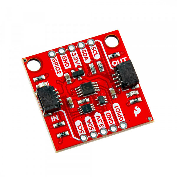
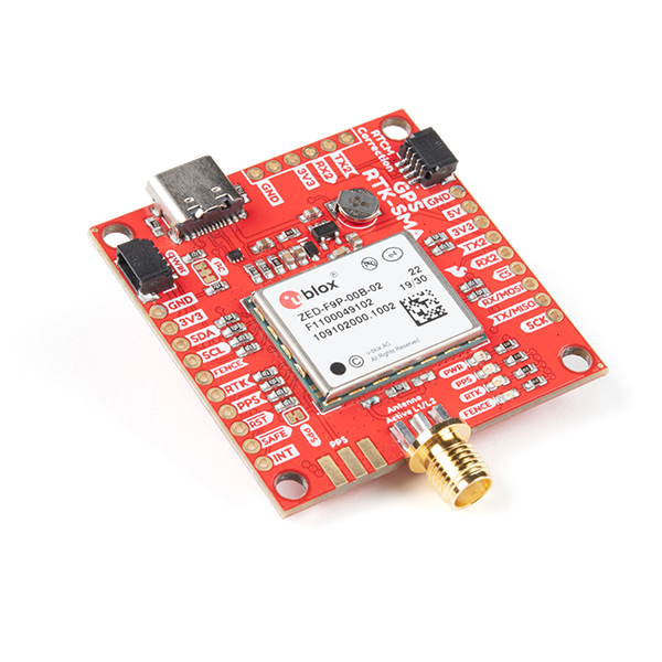
Many of our Qwiic products draw very little current when in standby, but there are some that draw considerably more. Products like our top-end u-blox GNSS boards in particular. There are times when you wish you could switch them off to save power, and the SparkFun Qwiic Power Switch (QPS) allows you to do exactly that!
In this tutorial, we'll go over the hardware and how to hookup the SparkFun Qwiic Power Switch to an Arduino. We will also go over an Arduino example to get started.
Required Materials
To follow along with this tutorial, you will need the following materials. You may not need everything though depending on what you have. Add it to your cart, read through the guide, and adjust the cart as necessary.
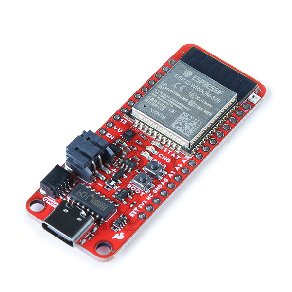
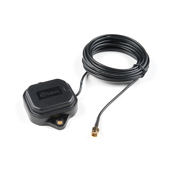
You will also need a Qwiic-enabled device and an additional Qwiic cable. In this case, we used a ZED-F9P for demonstration purposes. Of course, you could use a different Qwiic-enabled device.
Qwiic Cables
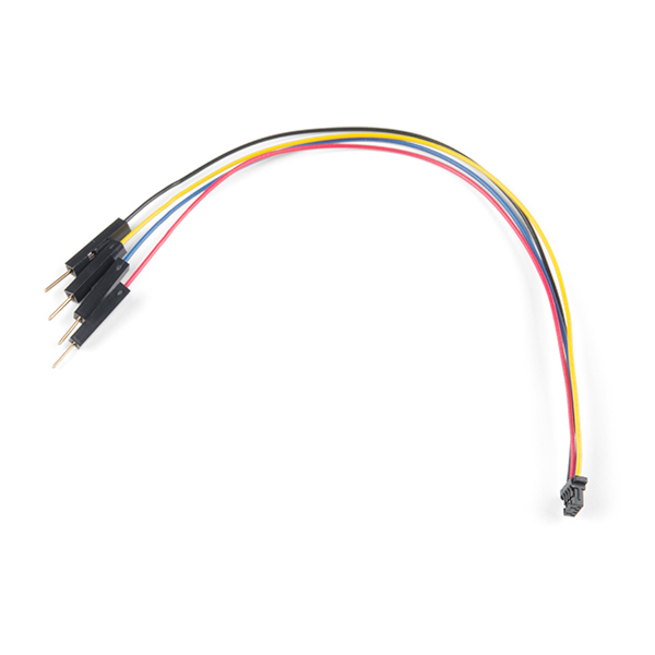
For those that want to take advantage of the Qwiic connector, you'll want to grab a Qwiic cable. There are a variety of other cable lengths available in the SparkFun catalog to choose from.
Tools (Optional)
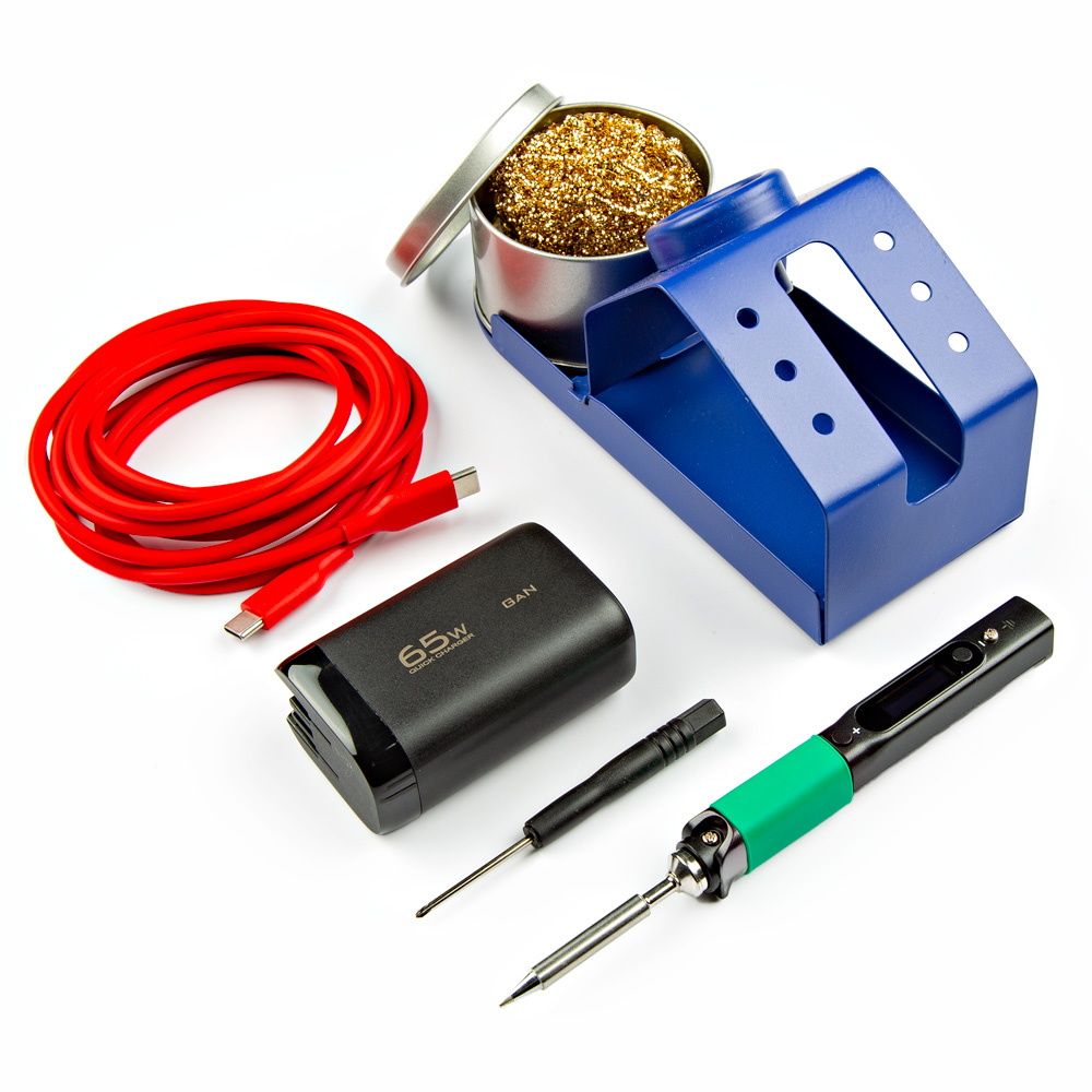
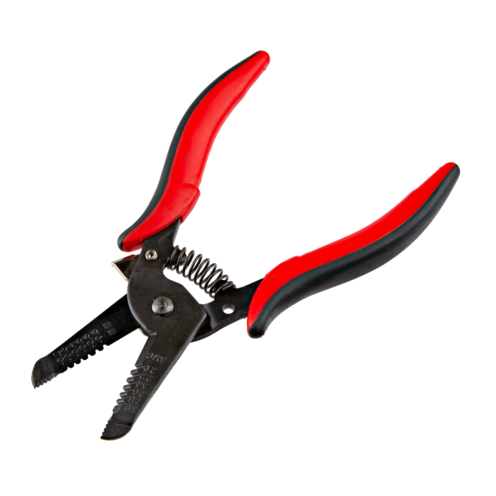
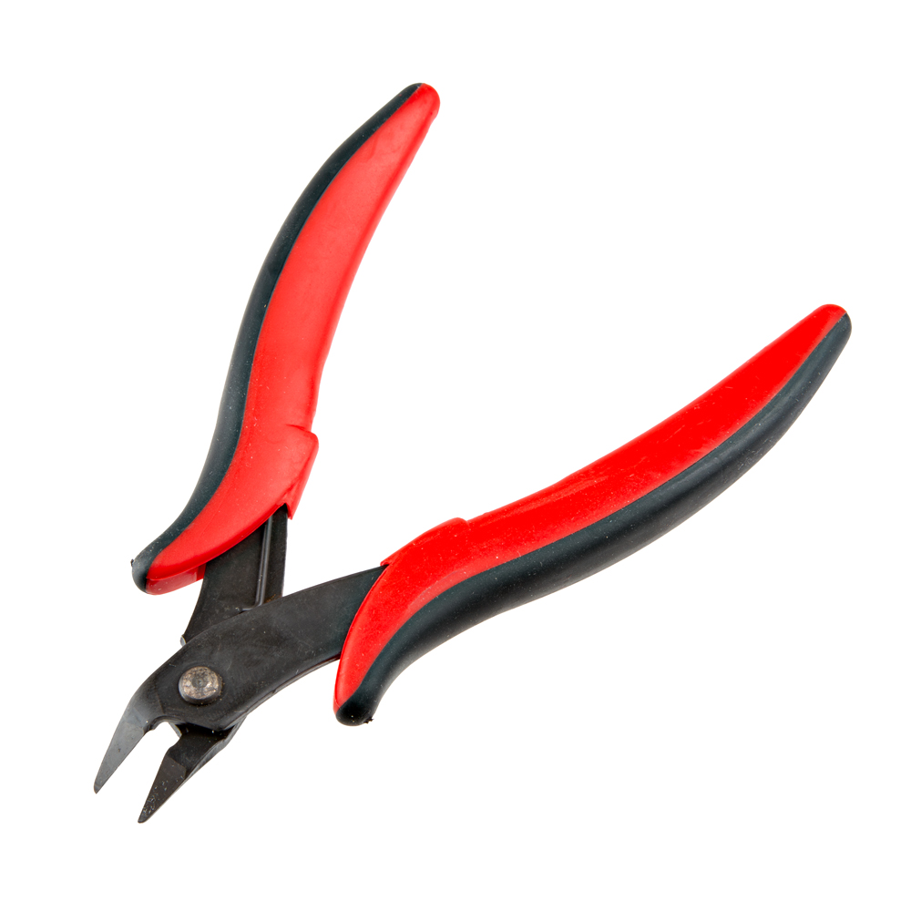
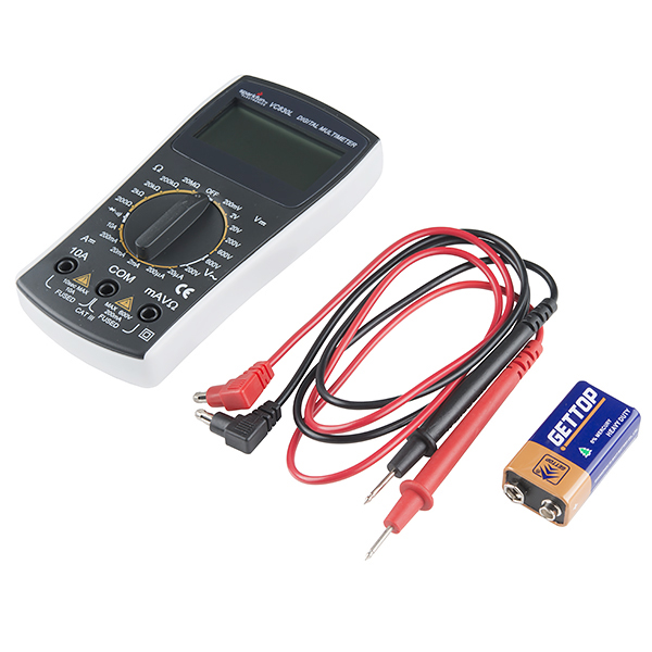
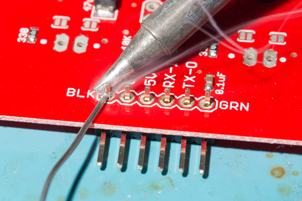
For users connecting to the plated through holes, you will need a soldering iron, solder, and general soldering accessories.
Prototyping Accessories (Optional)
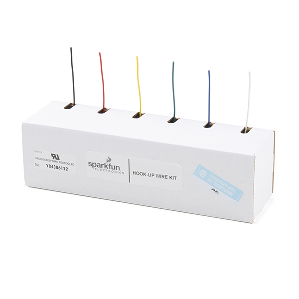
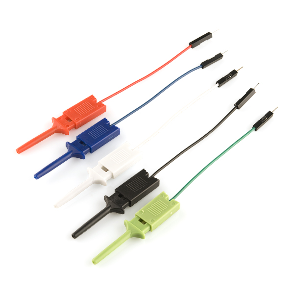
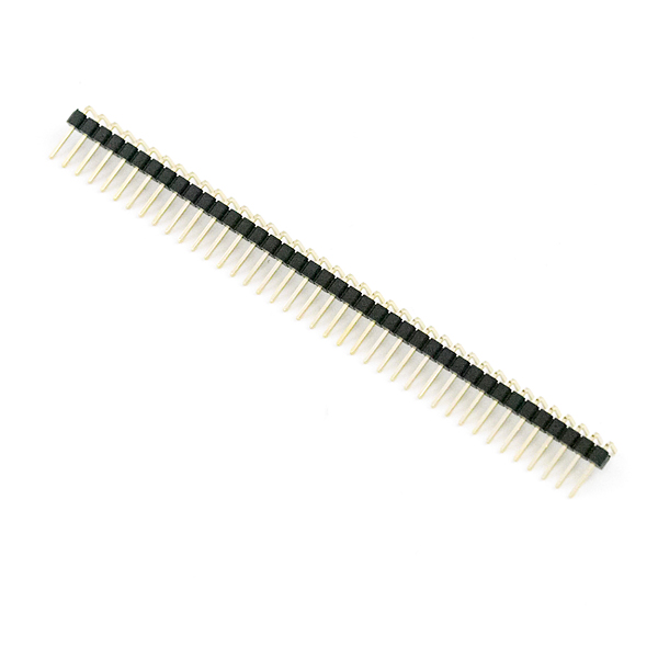
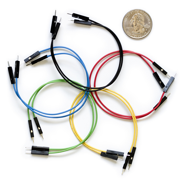
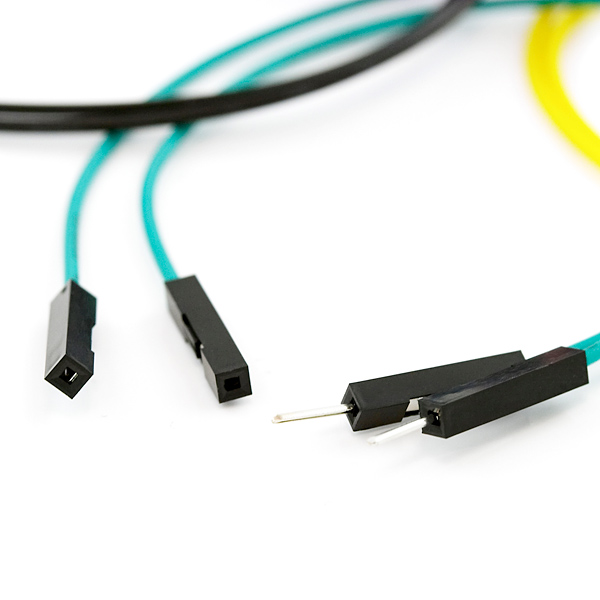
Depending on your setup, you may want to use IC hooks for a temporary connection. However, you will want to solder header pins to connect devices to the plated through holes for a secure connection.
Suggested Reading
If you aren't familiar with the Qwiic Connection System, we recommend reading here for an overview.
If you aren’t familiar with the following concepts, we also recommend checking out a few of these tutorials before continuing.
