Introduction
Many of our Qwiic products draw very little current when in standby, but there are some that draw considerably more. Products like our top-end u-blox GNSS boards in particular. There are times when you wish you could switch them off to save power, and the SparkFun Qwiic Power Switch (QPS) allows you to do exactly that!
In this tutorial, we'll go over the hardware and how to hookup the SparkFun Qwiic Power Switch to an Arduino. We will also go over an Arduino example to get started.
Required Materials
To follow along with this tutorial, you will need the following materials. You may not need everything though depending on what you have. Add it to your cart, read through the guide, and adjust the cart as necessary.
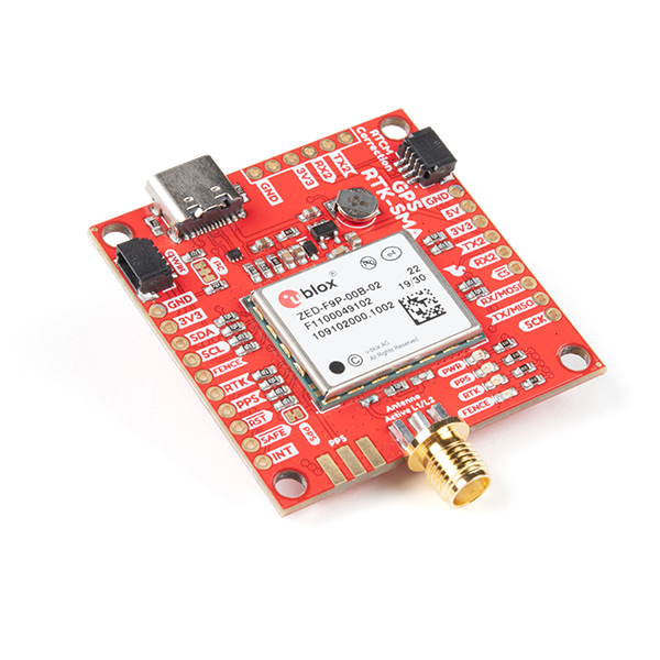
You will also need a Qwiic-enabled device and an additional Qwiic cable. In this case, we used a ZED-F9P for demonstration purposes. Of course, you could use a different Qwiic-enabled device.
Qwiic Cables
For those that want to take advantage of the Qwiic connector, you'll want to grab a Qwiic cable. There are a variety of other cable lengths available in the SparkFun catalog to choose from.
Tools (Optional)
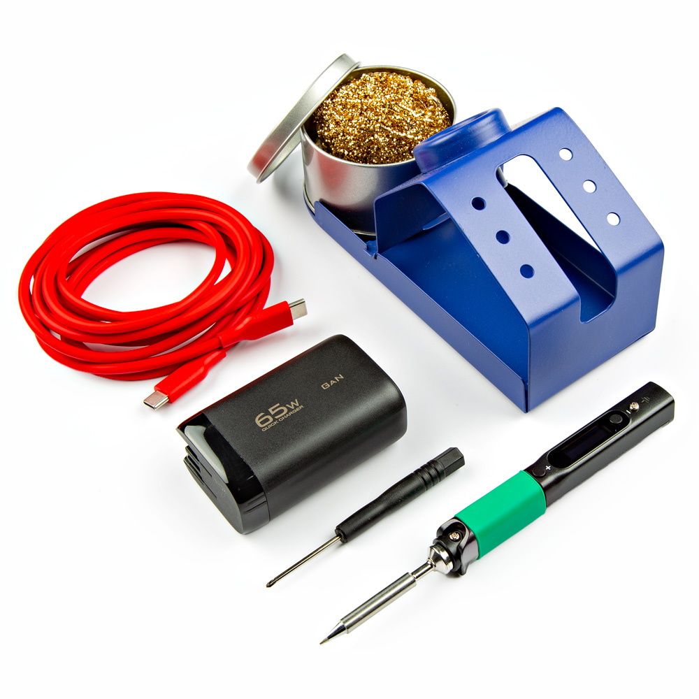
For users connecting to the plated through holes, you will need a soldering iron, solder, and general soldering accessories.
Prototyping Accessories (Optional)
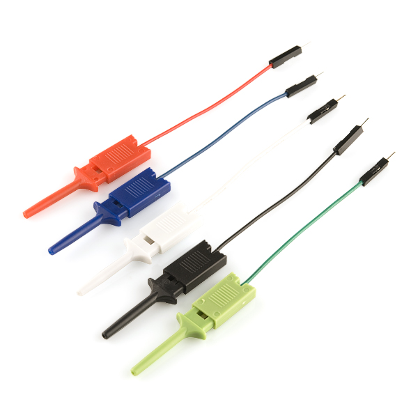
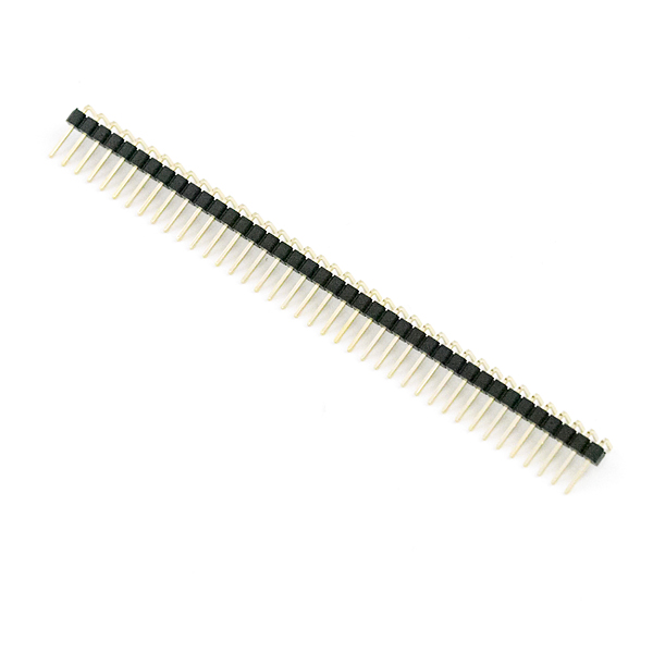
Depending on your setup, you may want to use IC hooks for a temporary connection. However, you will want to solder header pins to connect devices to the plated through holes for a secure connection.
Suggested Reading
If you aren't familiar with the Qwiic Connection System, we recommend reading here for an overview.
If you aren’t familiar with the following concepts, we also recommend checking out a few of these tutorials before continuing.
Hardware Overview
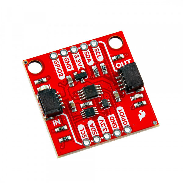
In this section, we will highlight the hardware and pins that are broken out on the SparkFun Qwiic Power Switch. For more information, check out our Resources and Going Further on the components used on the breakout board.
Power
To power the board, we recommend applying 3.3V to the 3.3V pin on the side labeled IN. While the IC's operating voltage is 2.3V to 5.5V, we recommend limiting the input voltage to 3.3V for the Qwiic Connect System. Below are the power pins that are broken out on the edge of the board.
- IN - 3.3V — This pin is the voltage input for the board. The recommended input voltage for this pin is 3.3V.
- OUT - 3.3V — This pin is the voltage output for the board. When the PCA9536 GPIO0 enables the transistor, any Qwiic enabled device that is connected to this side of the board will be powered by 3.3V.
- GND — Of course, is the common, ground voltage (0V reference) for the system.
Qwiic and I2C
The board includes two horizontal Qwiic connectors to connect Qwiic-enabled I2C devices. However, the board still breaks out 0.1"-spaced pins for users who prefer a soldered connection. The PCA9306 dual bidirectional I2C bus voltage level translator (the 8-pin IC closer to IN by the SDA and 3.3V PTHs) is included between the input and output Qwiic connectors. This acts as a bus isolator between the input and output pins for the data and clock lines. This prevents the pull-up resistors from feeding parasitic power to your Qwiic-enabled boards. The Qwiic Power Switch can also be used to isolate a 400kHz bus from a 100kHz bus; the slower bus on the output of the Qwiic Power Switch can be disconnected during fast-mode communication without disabling power.
- IN
- SCL — I2C clock on the PCA9306's input side.
- SDA — I2C data on the PCA9306's input side.
- 3.3V — This pin is the voltage input for the board. The recommended input voltage for this pin is 3.3V.
- OUT
- SCL — I2C clock on the PCA9306's output side.
- SDA — I2C data on the PCA9306's output side.
- 3.3V — This pin is the voltage output for the board. When the PCA9536 GPIO0 enables the transistor, any Qwiic enabled device that is connected to this side of the board will be powered by 3.3V.
- GND — Of course, is the common, ground voltage (0V reference) for the system. The GND PTHs are connected to both IN and OUT.
Connected on the input I2C bus is the TI PCA9536 4-Bit I2C I/O Expander (the bigger 8-pin IC located at the center of the board). This IC is used to toggle output 3.3V power and the PCA9306 I2C isolation. Its I2C device's 7-bit unshifted address is 0x41.
PCA9536 and GPIO Pins
The PCA9536 is a 4-bit GPIO IC that enables users to toggle the following GPIO pins through I2C. The I2C address of the PCA9536 is 0x41.
- GPIO0 — GPIO0 is connected to the MOSFET power switch. This controls the voltage between the 3.3V input pin and VOUT. When this transistor is turned off, power is removed from the I2C output's pull-up resistors.
- GPIO1 — GPIO1 is an extra GPIO pin.
- GPIO2 — GPIO2 is an extra GPIO pin.
- GPIO3 — This pin is connected to the PCA9306. This allows you to isolate the I2C output.
LEDs
The board includes two LEDs to indicate when power is available on the input and output's 3.3V pins. Both can be disabled with the jumpers on the back of the board.
Jumpers
Note
If this is your first time working with jumpers, check out the How to Work with Jumper Pads and PCB Traces tutorial for more information.
The back of the board includes jumpers to configure the board.
- I2C IN — By default, this three-pad jumper is closed. The three way jumper labeled I2C IN connects 3.3V to two 2.2kΩ pull-up resistors and to the I2C data and clock lines. If multiple devices are connected to the bus with the pull-up resistors enabled, the parallel equivalent resistance will create too strong of a pull-up for the bus to operate correctly. As a general rule of thumb, disable all but one pair of pull-up resistors if multiple devices are connected to the bus.
- I2C OUT — By default, this three-pad jumper is closed. Similar to the I2C IN jumper, this jumper is connects the VOUT net to two 2.2kΩ pull-up resistors and to the I2C data and clock lines. This VOUT is controlled by a MOSFET power switch and PCA9536's GPIO0. When the transistor is turned on, VOUT will connect to the input 3.3V pin.
- LED IN — By default, this jumper connects the LED to the input's 3.3V pin. Cutting this trace disables the LED.
- LED OUT — By default, this jumper connects the LED to the output's 3.3V pin. Cutting this trace disables the LED.
Board Dimensions
The board is 1.0" x 1.0" (25.4mm x 25.4mm). There are 2x mounting holes. You can use 4-40 standoffs to mount the board to a panel or enclosure.
Hardware Hookup
In this section, we will go over how to connect to the Qwiic Power Switch.
Connecting Via Qwiic
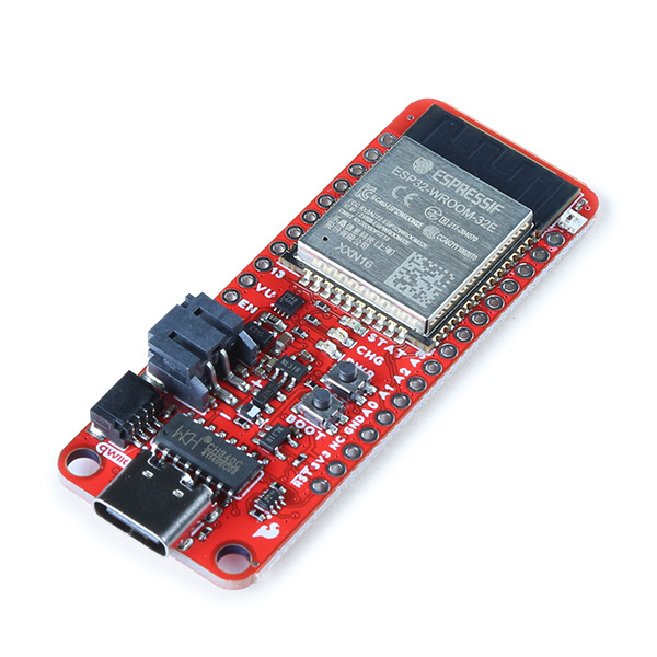
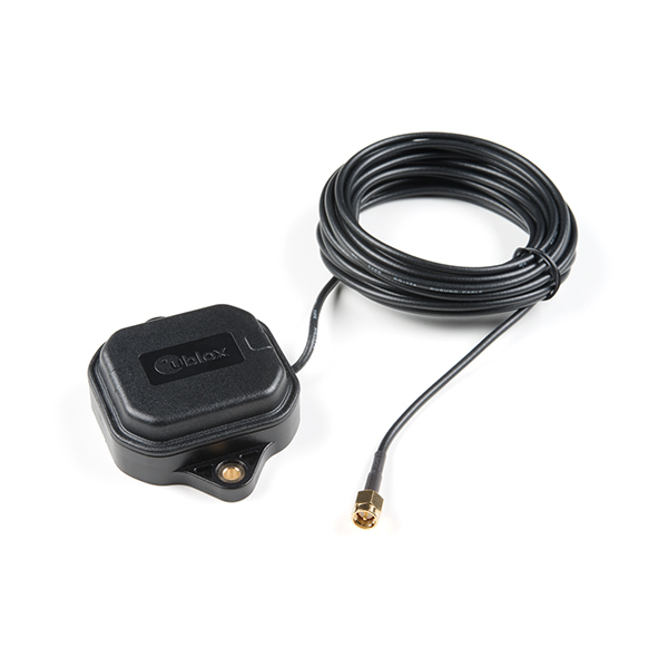
Insert a Qwiic cable between your Arduino microcontroller and the Qwiic Power Switch's IN port. In this case, we used the SparkFun Thing Plus ESP32- USB-C for the Arduino microcontroller. Then connect Qwiic cable between the Qwiic Power Switch's OUT port to the second Qwiic-enabled device. In this case, we used the ZED-F9P SMA breakout board when toggling power and isolating the I2C lines. We also connected an external multiband antenna to the ZED-F9P. When ready, connect a USB cable to the Arduino to program, power, and control the Qwiic Power Switch through a serial terminal.
Note
To isolate any Qwiic-enabled device, you will need to connect the Qwiic-enabled device from the OUT port.
Connecting via PTH
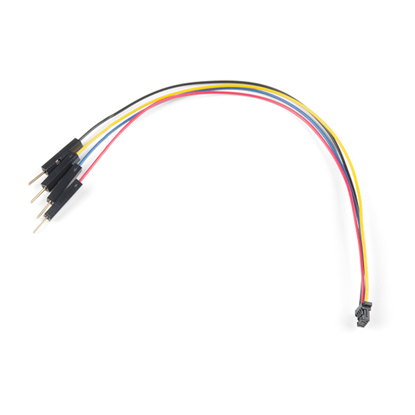
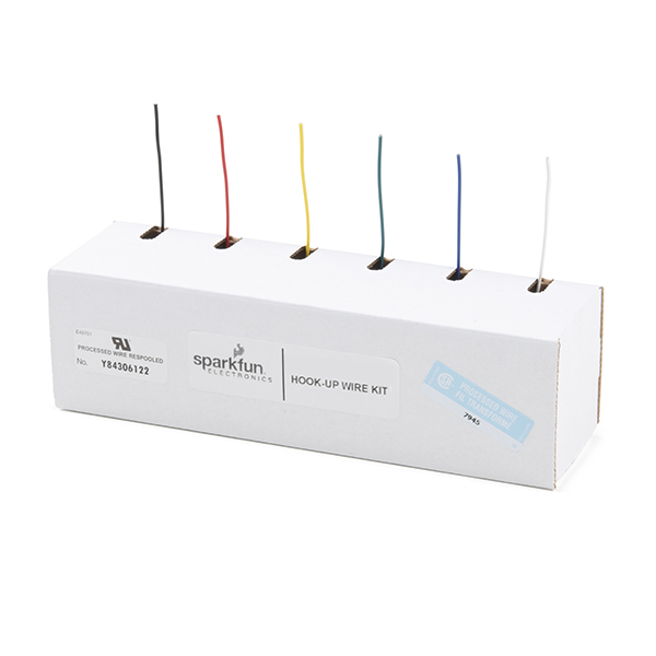
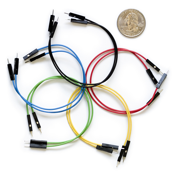
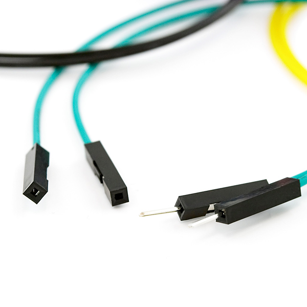
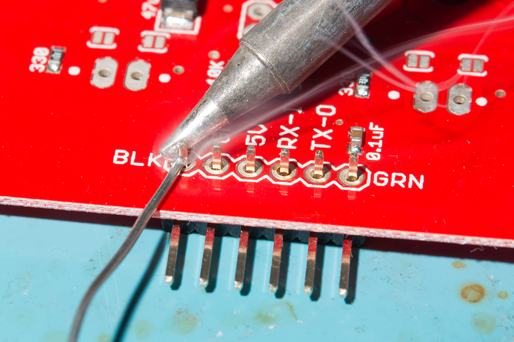
For temporary connections to the PTHs, you could use IC hooks to test out the pins. However, you'll need to solder headers or wires of your choice to the board for a secure connection. You can choose between a combination of header pins and jumper wires, or stripping wire and soldering the wire directly to the board.
Setting Up Arduino
Arduino
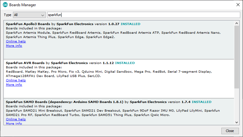
This example assumes you are using the latest version of the Arduino IDE on your desktop. If this is your first time using Arduino IDE, library, or board add-on, please review the following tutorials.
Note
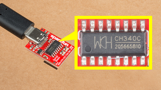
If you've never connected an CH340 device to your computer before, you may need to install drivers for the USB-to-serial converter. Check out our section on "How to Install CH340 Drivers" for help with the installation.
SparkFun has written a library to work with the Qwiic Power Switch. You can obtain this library through the Arduino Library Manager by searching for "SparkFun Qwiic Power Switch". Find the one written by SparkFun Electronics and install the latest version. Users who prefer to manually install the library can get it from the GitHub Repository or download the .ZIP by clicking the button below:
Arduino Example
Now that we have our library and board add-on installed, we can start experimenting with the breakout board. For the scope of this tutorial, we will highlight the example in the Arduino Library to get started.
Upload Arduino Example
After unzipping the compressed files, navigate to the example: File > Examples > SparkFun Qwiic Power Switch Arduino Library > Example1_PowerOnOff. This example allows you to toggle power and isolate the I2C lines for the OUT port through a serial terminal. The example also allows you to read GPIO1 and GPIO2.
For users using an Arduino microcontroller, select your board in the Tools menu (in our case the SparkFun ESP32 Thing Plus C) and the correct Port it enumerated on.
You can also copy or paste the code as shown below. Then click "Upload".
    /*
      Using the Qwiic Power Switch
      By: Paul Clark (PaulZC)
      Date: April 23rd, 2020

      Based extensively on:
      Using the PCA9536 -- Digital Output
      By: Jim Lindblom
      SparkFun Electronics
      Date: May 4, 2018

      License: This code is public domain but you buy me a beer if you use this and we meet someday (Beerware license).

      This example demonstrates how to use the Qwiic Power Switch and read the additional GPIO pins

      Hardware Connections:
      Attach your Arduino to the Qwiic Power Switch IN
      Plug your Qwiic device into the Qwiic Power Switch OUT
      https://www.sparkfun.com/products/15081
    */

    #include <Wire.h>

    #include <SparkFun_Qwiic_Power_Switch_Arduino_Library.h>

    QWIIC_POWER mySwitch;

    void setup(void)
    {
      Serial.begin(115200);
      while (!Serial)
        ; //Wait for user to open terminal
      Serial.println(F("Qwiic Power Switch Example"));

      Wire.begin();

      if (mySwitch.begin() == false) //Connect to the power switch using Wire port
      {
        Serial.println(F("Qwiic Power Switch not detected at default I2C address. Please check wiring. Freezing."));
        while (1)
          ;
      }

      // Configure GPIO1 and GPIO2 as INPUT
      mySwitch.pinMode(1, INPUT);
      mySwitch.pinMode(2, INPUT);

      Serial.println(F("1) Enable power and I2C"));
      Serial.println(F("2) Disable power and I2C"));
      Serial.println(F("3) Enable I2C isolation"));
      Serial.println(F("4) Disable I2C isolation"));
    }

    void loop()
    {
      if (Serial.available())
      {
        byte incoming = Serial.read();

        if (incoming == '1')
        {
          // Switch the power on
          mySwitch.powerOn();
          Serial.println(F("Power is ON. I2C isolation is disabled."));
        }
        else if (incoming == '2')
        {
          // Switch the power off
          mySwitch.powerOff();
          Serial.println(F("Power is OFF. I2C isolation is enabled."));
        }
        else if (incoming == '3')
        {
          // Enable I2C isolation = I2C bus _is_ isolated
          mySwitch.isolationOn();
          Serial.println(F("I2C isolation enabled. I2C is isolated."));
        }
        else if (incoming == '4')
        {
          // Disable I2C isolation = I2C bus _is not_ isolated
          mySwitch.isolationOff();
          Serial.println(F("I2C isolation disabled. I2C is not isolated."));
        }

        // Read and print the GPIO1/GPIO2 state
        Serial.print(F("GPIO1 is: "));
        Serial.println(mySwitch.digitalRead(1));
        Serial.print(F("GPIO2 is: "));
        Serial.println(mySwitch.digitalRead(2));

        // Read any extra Serial bytes (e.g. CR or LF)
        while (Serial.available() > 0)
        {
          Serial.read();
        }
      }
    }
Tip
Instead of reading GPIO1 and GPIO2, you can write to the GPIO pins to set the pins HIGH or LOW. You will need to change the following lines of code in the setup() and loop() functions where the GPIO1 and GPIO2 are initialized and read.
setup(){
  .
  .
  .
  // Configure GPIO1 and GPIO2 as INPUT
  mySwitch.pinMode(1, INPUT);
  mySwitch.pinMode(2, INPUT);
  .
  .
  .
}

void loop() {
      .
      .
      .
      // Read and print the GPIO1/GPIO2 state
      Serial.print(F("GPIO1 is: "));
      Serial.println(mySwitch.digitalRead(1));
      Serial.print(F("GPIO2 is: "));
      Serial.println(mySwitch.digitalRead(2));
      .
      .
      .
}
Instead of an INPUT, you will change each GPIO pin as an OUTPUT. Additionally, you will need to set the pin as a HIGH or LOW.
setup(){
  .
  .
  .
  // Configure GPIO1 and GPIO2 as OUTPUT
  mySwitch.pinMode(1, OUTPUT);
  mySwitch.pinMode(2, OUTPUT);
  .
  .
  .
}

void loop() {
      .
      .
      .
      // Write to GPIO1 & GPIO2
      Serial.println(F("GPIO1 is set to HIGH."));
      mySwitch.digitalWrite(1, HIGH);
      Serial.println(F("GPIO2 is set to LOW."));
      mySwitch.digitalWrite(2, LOW);
      .
      .
      .
}
To test, simply attach an LED with a current limiting resistor between the GPIO and GND. The LED should light up when the pin is HIGH and turn off when set to LOW. Of course, you can also connect a multimeter set to read the voltage between the GPIO pin nd GND. The GPIO pin should read 3.3V when set to HIGH and 0V when set to LOW.
After uploading the code, open the Serial Monitor or terminal emulator of your choice with the baud rate set to 115200. You will be presented with a few options to configure the Qwiic Power Switch:
- 1 — Power is ON I2C isolation is disabled.
- 2 — Power is OFF. I2C isolation is enabled.
- 3 — I2C isolation enabled. I2C is isolated.
- 4 — I2C isolation disabled. I2C is not isolated.
Let's send a 2 to turn power off the Qwiic Power Switch's output and isolate the I2C data and clock lines. The Arduino will output a message: "Power is OFF. I2C isolation is enabled." The Arduino will also read the Qwiic Power Switch's GPIO1 and GPIO2. In this case, there was nothing connected to either GPIO so the pin reading was 1 indicating a HIGH. If there was a logic LOW, the pin would read 0 indicating a LOW.
If the Qwiic-enabled board includes a built-in LED, you can see if power is enabled. The power LED (as well as any other LED on the board) should have turned off as soon as power is disabled at the OUT port. In this case, the Qwiic Power Switch's OUT and ZED-F9P's LEDs when power was disabled and I2C isolation is enabled.
Note
If power is OFF at the OUT port but you decide to disable I2C isolation, you may notice a voltage at the 3.3V OUT pin from the pull-up resistors connected to the I2C lines.
If you would like to verify that the I2C lines are isolated, try turning the power back on by sending a 1 and then sending a 3 to isolate the I2C lines. While still applying power to the Qwiic Power Switch, try re-uploading code to the Arduino for the Qwiic-enabled board that is connected to the Qwiic Power Switch's OUT. Assuming that the example code checks for the Qwiic-enabled device, you should receive a message indicating that the Qwiic-enabled device was not detected.
Note
Of course, you could also use the Arduino I2C scanner to scan the I2C bus and detect I2C devices. When scanning, you should only see the Qwwic Power Switch and anything that was connected before the IN port. Anything after the OUT will not be detected on the OUT port if power was disabled or the lines were isolated.
Troubleshooting
General Troubleshooting Help
Note
Not working as expected and need help?
If you need technical assistance and more information on a product that is not working as you expected, we recommend heading on over to the SparkFun Technical Assistance page for some initial troubleshooting.
If you don't find what you need there, the SparkFun Forums are a great place to find and ask for help. If this is your first visit, you'll need to create a forum account to search product forums and post questions.
Resources
Now that you've successfully got your SparkFun Qwiic Power Switch up and running, it's time to incorporate it into your own project! For more information, check out the resources below:
