Introduction
-
SparkPNT RTK Facet mosaic
SKU: GPS-29688

-
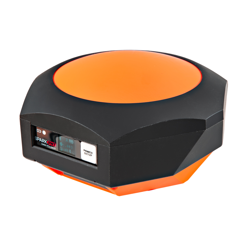
Designed and manufactured in Boulder, Colorado, USA, and utilizing the multi-band mosaic-X5 from Septentrio, the SparkPNT RTK Facet mosaic is the top of the line receiver for high precision geolocation and surveying needs. For basic users, it's incredibly easy to get up and running; for advanced users, the RTK Facet mosaic is a flexible and powerful tool. With just the press of a button, the RTK Facet mosaic is the fastest way to take centimeter-grade measurements. With a subscription to the PointPerfect Flex NTRIP/RTCM service or any other correction service, 10mm Real Time Kinematic fixes are less than a minute away. By connecting your phone to the RTK Facet mosaic over Bluetooth®, your phone or tablet can receive the NMEA output and work with most GIS software programs. This is exactly how $10,000 surveying devices have been operating for the past decade - we just made it faster, more precise, and a lot more economical.
The RTK Facet mosaic works with common GIS software for Android and iOS including SW Maps Android / iOS, Field Genius, SurvPC, Survey Master, Vespucci, QGIS, QField, and any GIS software that supports NMEA over Bluetooth.
Under the hood of the SparkPNT RTK Facet mosaic is an ESP32-WROVER-E connected to a mosaic-X5 GNSS multi-band receiver, and a variety of peripheral hardware (LiPo fuel gauge, microSD, etc). Additionally, housed under the dome of the RTK Facet mosaicis a surveyor grade L1/L2/L5 antenna. This antenna is a unique combination of elements designed to receive the GNSS signals (L1/L2/L5). The RTK Facet mosaic is programmed in Arduino and can be tailored by you to fit whatever your needs may be.
This device can be used in five modes:
- GNSS Positioning (~30cm accuracy) - also known as Rover
- GNSS Positioning with RTK (1.4cm accuracy) - also known as Rover with RTK Fix
- GNSS Base Station
- GNSS Base Station NTRIP Server
At Power On the device will enter Rover or Base mode; whichever state the device was in at the last power down. When the POWER/SETUP button is pressed momentarily, a menu is presented to change the RTK Facet mosaic from Rover to Base mode or vice-versa. The display will indicate the change with a small car (Rover) or flag (Base) icon.
In Rover mode the RTK Facet mosaic will receive
L1,L2, andL5GNSS signals from the four constellations (GPS, GLONASS, Galileo, and BeiDou). The device will calculate the position based on the combination of GNSS. If the device has been registered with PointPerfect or any other correction service, the receiver will quickly (within 60 seconds) obtain an RTK float, then fix. Similar to a standard grade GPS receiver, the RTK Facet mosaic will output industry standard NMEA sentences at 4Hz and broadcast them to any paired Bluetooth® device. The end user will need to parse the NMEA sentences using commonly available mobile apps, GIS products, or embedded devices (there are many open source libraries). Unlike standard grade GPS receivers that have 2500mm accuracy, the accuracy in this mode is approximately 10 to 60mm horizontal positional accuracy.In Base mode the device will enter Base Station mode. This is used when the device is mounted to a fixed position (like a tripod or roof). The RTK Facet mosaic will initiate a survey. After 60 to 120 seconds the survey will complete and the RTK Facet mosaic will begin transmitting RTCM correction data out the radio port. A base is often used in conjunction with a second RTK Facet mosaic (or RTK Torch, Facet, Surveyor, Express, Express Plus, etc) unit set to Rover to obtain the 10mm accuracy. Said differently, the Base sits still and sends correction data to the Rover, so that the Rover can output really accurate position data for its location.
In addition to supplying position data, the RTK Facet mosaic is capable of logging NMEA and raw GNSS satellite data for post processing making it ideal for research and advanced positioning applications.
The RTK Facet mosaic is an open-source hardware product meaning you can fully obtain, see, and even modify the electrical and mechanical design files. This allows for easier maintenance and repair over time.
The SparkPNT RTK Facet mosaic kit includes everything you need: the enclosed device, thread adapter, charger, data cables, and carrying case. It does NOT include a surveying pole (any additional items will need to be purchased separately).
 Purchase from SparkFun
 Permanent Installation
The SparkPNT RTK Facet mosaic is not designed for permanent outdoor mounting. Please use the RTK mosaic-X5 or the RTK Reference Station that is located inside or protected from the elements. Or, for a DIY solution, the ESP32 attached to our ZED-F9P breakout is a great way to go. See our How to Build a DIY GNSS Reference Station tutorial for more information.
Completely Open-Source
- The RTK Everywhere firmware is open-source, so users can obtain, check, and even modify the device's functionality. This allows for easier feature expansion, bug maintenance, and longer device longevity.
- Additionally, the hardware is also open-source, so users can obtain, check, and even modify the device's design.
Required Materials
To get started, users will need a few items. Some users may already have a few of these items, feel free to adjust accordingly.
- Computer or mobile device with Bluetooth® and WiFi capabilities
- SparkPNT RTK Facet mosaic
- Telescopic Surveying Pole
- PointPerfect Registration
-
SparkPNT RTK Facet mosaic
GPS-29688 -

Telescopic Surveying Pole
GPS-25795
Serial Transceivers, UART Adapters, and USB Cables
To configure the UART ports that are broken out on the board, users will need a UART adapter. Once configured, the UART ports can utilize one of our RF transceivers to send/receive RTCM messages.
-
SiK Telemetry Radio V3 - 915MHz, 100mW
WRL-19032 -
SparkFun LoRaSerial Kit - 915MHz (Enclosed)
WRL-20029 -
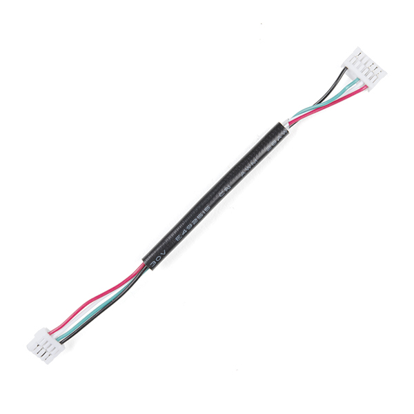
GHR-04V-S to GHR-06V-S Cable - 100mm
CAB-17854
-
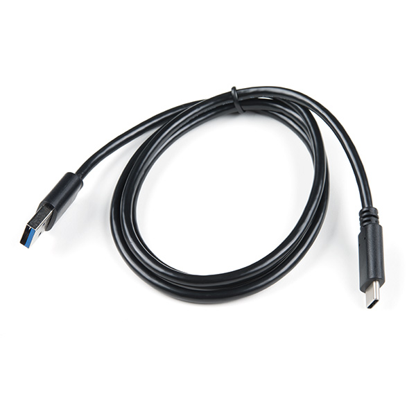
USB 3.1 Cable A to C - 3 Foot
CAB-14743 -
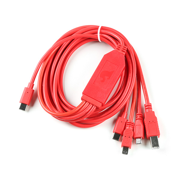
SparkFun 4-in-1 Multi-USB Cable - USB-C Host
CAB-21271 -
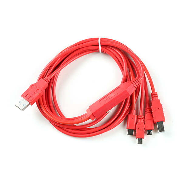
SparkFun 4-in-1 Multi-USB Cable - USB-A Host
CAB-21272
Jumper Modification
To modify the jumpers, users will need soldering equipment and/or a hobby knife.
New to jumper pads?
Check out our Jumper Pads and PCB Traces Tutorial for a quick introduction!
-

How to Work with Jumper Pads and PCB Traces
-
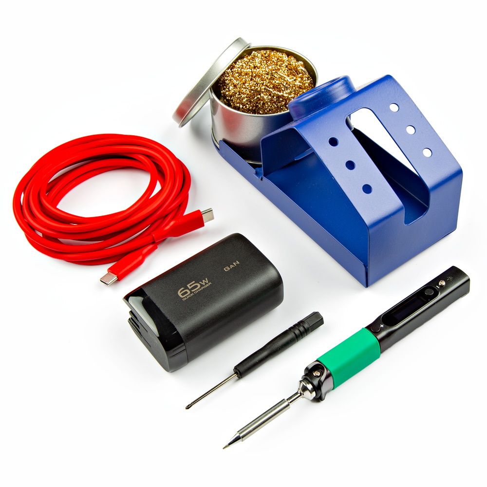
PINECIL Soldering Iron Kit
KIT-24063 -
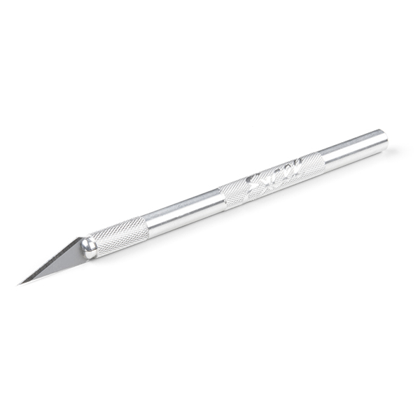
Hobby Knife
TOL-09200 -
Chip Quik No-Clean Flux Pen - 10mL
TOL-14579 -

Solder Wick #2 5ft. - Generic
TOL-09327
Suggested Reading
As a more sophisticated product, we will skip over the more fundamental tutorials (i.e. Ohm's Law and What is Electricity?). However, below are a few tutorials that may help users familiarize themselves with various aspects of the board.
Tip
Check out the www.gps.gov website to learn more about the U.S.-owned Global Positioning System (GPS) and the Global Navigation Satellite Systems (GNSS) of other countries.
-
GPS Basics
-
What is GPS RTK?
-
SparkFun RTK Everywhere Product Manual
-
Setting up a Rover Base RTK System
-
How to Build a DIY GNSS Reference Station
-

SparkFun RTK Facet L-Band Hookup Guide
-
Serial Communication
-
Serial Terminal Basics
-
I2C
Related Blog Posts
Additionally, users may be interested in these blog post articles on GNSS technologies:
-

GPS vs GNSS
-

What is Correction Data?
-

Real-Time Kinematics Explained
-
New Video: Unlocking High-Precision RTK Positioning
-

DIY RTK Surveying
Hardware Overview
The RTK Facet mosaic is a fully enclosed and pre-programmed device. There are very few things to worry about or configure, but we will cover the basics here.
Design Files
The design of the SparkPNT RTK Facet mosaic is similar to previous generations in our line Facet line of products. However, we have made some modifications to the design to enhance the durability of this product. The PCB design features three separate board components:
- A central board that hosts primary components of the RTK Facet mosaic, such as the ESP32-WROVER-E, mosaic-X5, etc.
- A peripheral board that provides connections to the RTK Facet mosaic
- A display board that is the primary interface for the RTK Facet mosaic
-
Design Files
-
Need Dimensions?
For the board dimensions, users can download the KiCad files for these board. These files can be opened in KiCad and measurements can be made with the measuring tool.
KiCad - Free Download!
KiCad is free, open-source CAD program for electronics. Click on the button below to download their software. (*Users can find out more information about KiCad from their website.)
Download  Measuring Tool
This video demonstrates how to utilize the dimensions tool in KiCad, to include additional measurements:

Replacement Parts
Kit Parts
-
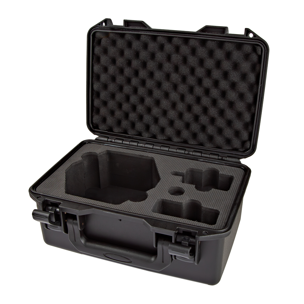
SparkPNT RTK Facet Ruggedized Hardcase
PRT-27115 -
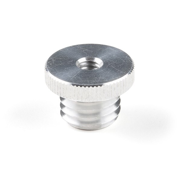
Antenna Thread Adapter - 1/4in. to 5/8in.
PRT-17546 -
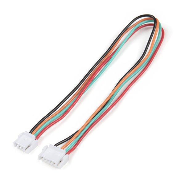
JST-GHR-04V to JST-GHR-06V Cable - 1.25mm pitch
CAB-17239 -
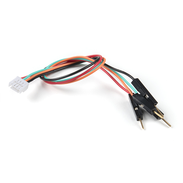
Breadboard to JST-GHR-04V Cable - 4-Pin x 1.25mm Pitch
CAB-17240 -
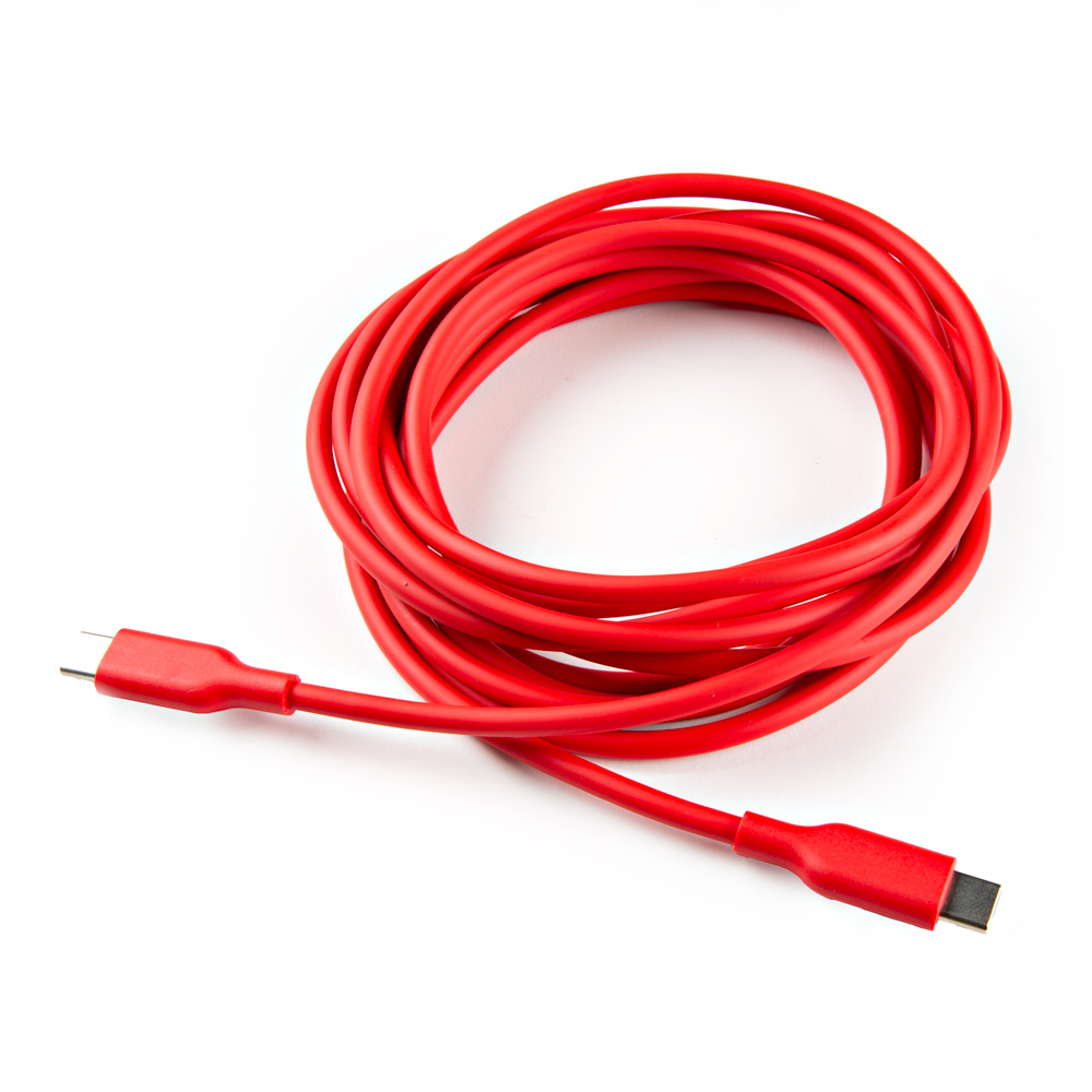
USB-A to USB-C Cable - 3m (Flexible Silicone)
CAB-24060 -
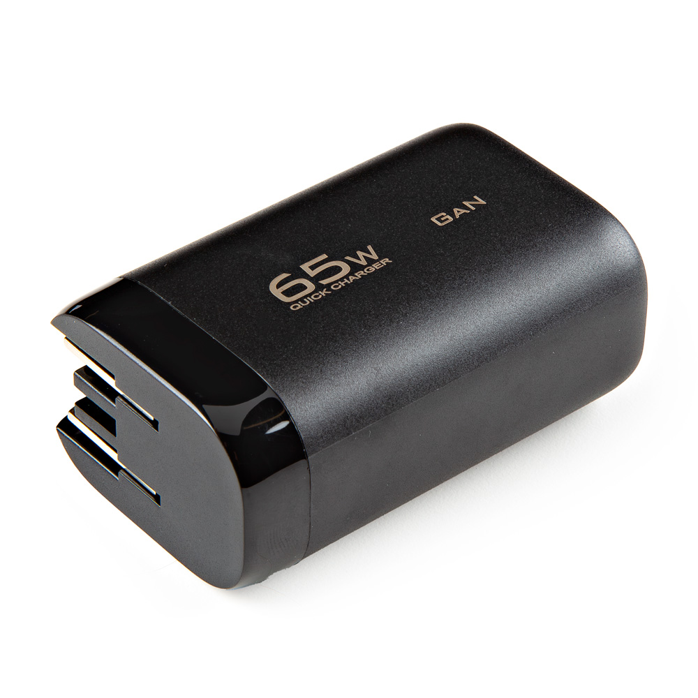
USB A and C Power Delivery (PD) Wall Adapter - 65W
TOL-24059
Internal Components
- M2.2-0.98 x 10mm Thread Forming Screws - Phillips Head
- M3-1.34 x 10mm Thread Forming Screws - Phillips Head
Power/Setup Button

The POWER/SETUP button on the front of the RTK Facet mosaic.
The RTK Facet mosaic has a POWER/SETUP button to turn the device on/off or for in-field configuration changes.
- Press and hold the button down, to power the RTK Facet mosaic
ONorOFF. - Short presses of the button will cause the RTK Facet mosaic to change modes. This device can be used in five modes:
- Rover
- GNSS Positioning (~30cm accuracy) - also known as Rover
- GNSS Positioning with RTK (1.4cm accuracy) - also known as Rover with RTK Fix
- Base
- GNSS Base Station
- GNSS Base Station as NTRIP Server
- Rover
Power Switch
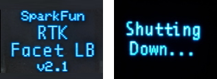
The splash screen of RTK Facet mosaic display showing the firmware version number and the device powering off.
The Power button turns the unit on or off:
- Press and hold the power button until the display illuminates.
- Press and hold the power button at any time to turn the unit off.
Battery Power
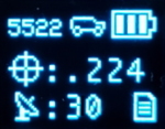
RTK Facet mosaic display, showing the battery level.
The RTK Facet mosaic has a large, built-in 6000mAh lithium polymer battery that will enable over 25 hours of field use between charging. If more time is needed a common USB power bank can be attached boosting the field time to any amount needed.
Info
For more information, please refer to the Internal Batter section
Charge LED

Charge LED indicator on the RTK Facet mosaic.
The Charge LED is located on the front face. It will illuminate any time there is an external power source and will turn off when the internal battery is charged. With the unit fully powered down, charging takes approximately 6 hours from a 1A wall supply or 12 hours from a standard USB port. The RTK Facet mosaic can run while being charged but it increases the charge time. Using an external USB battery bank to run the device for extended periods or running the device on a permanent wall power source is supported.
Operation Modes
At Power On the device will enter Rover or Base mode; whichever state the device was in at the last power down. When the POWER/SETUP button is pressed momentarily, a menu is presented to change the RTK Facet mosaic from Rover to Base mode or vice-versa. The display will indicate the change with a small car (Rover) or flag (Base) icon.
Rover Mode
In Rover mode the RTK Facet mosaic will receive L1, L2, and L5 GNSS signals from the four constellations (GPS, GLONASS, Galileo, and BeiDou) and calculate the position based on these signals. Similar to a standard grade GPS receiver, the RTK Facet mosaic will output industry standard NMEA sentences at 4Hz and broadcast them over any paired Bluetooth® device. The end user will need to parse the NMEA sentences using commonly available mobile apps, GIS products, or embedded devices (there are many open source libraries). Unlike standard grade GPS receivers that have 2500mm accuracy, the accuracy in this mode is approximately 300mm horizontal positional accuracy.
-
- w/ RTK Fix
-
If the device is in Rover mode and RTCM correction data is sent over Bluetooth® or into the radio port, the device will automatically enter Positioning with RTK mode. In this mode RTK Facet mosaic will receive
L1/L2/L5signals from the antenna; and correction data from a base station. The receiver will quickly (within a second) obtain an RTK float, then fix. The NMEA sentences will have increased accuracy of 10mm horizontal and 10mm vertical accuracy.- The RTCM correction data is most easily obtained over the Internet using a free app on your phone (see our SW Maps (Android/iOS) or Lefebure NTRIP instructions) and sent over Bluetooth® to the RTK Facet mosaic.
- The RTCM correction data can also be received over an external cellular or radio link from a 2nd RTK Facet, Surveyor, Express, etc. that is setup as a base station.
Base Mode
In Base mode the device will enter Base Station mode. This is used when the device is mounted to a fixed position (like a tripod or roof). The RTK Facet mosaic will initiate a survey. After 60 to 120 seconds the survey will complete and the RTK Facet mosaic will begin transmitting RTCM correction data out the radio port. A base is often used in conjunction with a second RTK Facet mosaic (or RTK Surveyor, Express, Express Plus, etc) unit set to Rover to obtain the 10mm accuracy. Said differently, the Base sits still and sends correction data to the Rover; so that the Rover can calculate a really accurate position.
Connectors

The SparkFun RTK Facet mosaic connectors shown with the dust cover removed.
There are a variety of connectors protected under a dust flap.
USB

This USB-C connector is used for four purposes:
- Charging the device
- Configuring the RTK Facet mosaic, and reprogramming the ESP32
- Configuring or updating the firmware of the mosaic-X5 (as needed)
There is a USB hub built into the RTK Facet mosaic. When you attach the device to your computer it will enumerate as two COM ports. In the mosaic-X5 firmware, these are named the USB1 and USB2 COM ports.
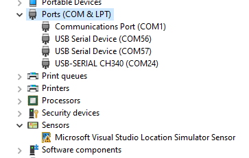
In the image above, the USB-SERIAL CH340 is the ESP32 and the USB Serial Device is the mosaic-X5.
Tip - USB Drivers
CH340 UART Converter
The CH340 serial-to-USB converter allows users to interface with the ESP32-WROVER-E module through the USB-C connector. To utilize the CH340, users may need to install a USB driver, which can be downloaded from the manufacturer website.
Linux
A USB driver should not be required for most Linux based operating systems; the standard Linux CDC-ACM driver is usually sufficient. However, if necessary, users can try the USB driver below:
CH341SER_LINUX.ZIP
mosaic-X5
On Windows computers, a USB driver is required to recognize and interact with the mosaic-X5 module through the USB interface.
-
Windows
The USB driver necessary to recognize and interact with the mosaic-X5 module through the USB interface, can be installed through two methods:
- RxTools Software Suite (1)
- mosaic-X5 GNSS Receiver Module (2)
- The driver is installed during the installation process.
- The installation file for the Windows USB driver will be available from the mass-storage device when the board is initially connected to the computer.
Having Trouble?
For users who are having trouble installing the USB driver, we have an archived version (v3.0.2) of the installation file. Users can download version 3.0.2 of the driver, by clicking on the button below.
Download USB Driver (v3.0.2) Latest Driver
This driver version was archived at the time that the mosaic-X5 hookup guide was written. Please do not request for the file to be updated.
For the latest USB driver from Septentrio, please install their driver through the RxTools software suite.
Linux
On Linux, the standard Linux CDC-ACM driver is suitable for the mosaic-X5 module.
Configuring the RTK Facet mosaic can be done over the USB-Serial CH340 COM port via serial text menu. Various debug messages are printed to this port at 115200bps and a serial menu can be opened to configure advanced settings. The mosaic-X5 can be configured over the USB Serial Device port using web interface. It's not necessary in normal operation but is handy for tailoring the receiver to specific applications.
RADIO

This port is used when an external cellular or radio link is needed. Internally, it is routed to the mosaic-X5 COM2 UART port. The baud rate is configurable; the default is 57600 baud. This port is not used if you transfer RTCM from your phone to the RTK Facet mosaic over Bluetooth.
This 4-pin JST connector can be used to allow RTCM correction data to flow into the device when it is acting as a Rover or out of the device when it is acting as a Base. The connector is a 4-pin locking 1.25mm JST SMD connector (1). The RTK Facet mosaic comes with a cable to interface to this connector, but additional cables can be purchased separately.
-
- SMD board connector
- part#: SM04B-GHS-TB
- Mating cable connector
- part#: GHR-04V-S
- SMD board connector
You will most likely connect one of our Serial Telemetry Radios to this port, if you don't have access to a correction source on the internet. The pinout is 3.5-5.5V/TX/RX/GND from left to right as pictured. 3.5V to 5.5V is provided by this connector to power a radio with a voltage that depends on the power source. If USB is connected to the RTK Facet mosaic then voltage on this port will be 5V (+/-10%). If running off of the internal battery then voltage on this port will vary with the battery voltage (3.5V to 4.2V depending on the state of charge). This port is capable of sourcing up to 600mA and is protected by a PTC (resettable fuse). This port should not be connected to a power source.
DATA

This port is used when an external system is connected such as a rover, car, timing equipment, camera triggers, etc. This port is not used if you transfer NMEA positional data to your phone from the RTK Facet mosaic over Bluetooth.
This 4-pin JST connector is used to output and input a variety of data to the RTK Facet mosaic. The connector is a 4-pin locking 1.25mm JST SMD connector (1). The RTK Facet mosaic comes with a cable to interface to this connector, but additional cables can be purchased separately.
-
- SMD board connector
- part#: SM04B-GHS-TB
- Mating cable connector
- part#: GHR-04V-S
- SMD board connector
Internally, the Data connector is connected to a digital mux allowing one of four software selectable setups. See the Ports Menu for a description of each option.:
- NMEA - The
TXpin outputs any enabled messages (NMEA and RTCM) at a default of 230400 baud (configurable 9600 to 921600bps). TheRXpin can receive RTCM messages for an RTK fix. Internally,TXandRXare routed to the mosaic-X5 COM3 UART port. - PPS/Trigger - The
TXpin outputs the pulse-per-second signal that is accurate to 30ns RMS. TheRXpin is connected to theEVENTApin on the mosaic-X5, allowing for events to be measured with incredibly accurate nano-second resolution. Useful for things like audio triangulation. - I2C - The
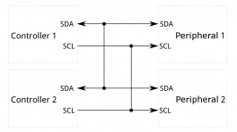
TXpin operates asSCL,RXpin asSDAon the I2C bus. This allows additional sensors to be connected to the I2C bus. - GPIO - The
TXpin operates as a DAC capableGPIO 21on the ESP32. TheRXpin operates as a ADC capable input (GPIO39) on the ESP32. This is useful for custom applications.
Most applications do not need to utilize this port and will send the NMEA position data over Bluetooth. This port can be useful for sending position data to an embedded microcontroller or single board computer. The pinout is 3.3V/TX/RX/GND. 3.3V from left to right as pictured, which is provided by this connector to power a remote device if needed. While the port is capable of sourcing up to 600mA, we do not recommend more than 300mA. This port should not be connected to a power source.
microSD

This slot accepts standard microSD cards up to 32GB formatted for FAT32.
The following messages are supported for logging:
- NMEA-ALM
- NMEA-AVR
- NMEA-DTM
- NMEA-GBS
- NMEA-GFA
- NMEA-GGA
- NMEA-GGK
- NMEA-GGQ
- NMEA-GLL
- NMEA-GMP
- NMEA-GNS
- NMEA-GRS
- NMEA-GSA
- NMEA-GST
- NMEA-GSV
- NMEA-HDT
- NMEA-HRP
- NMEA-LLK
- NMEA-LLQ
- NMEA-RBD
- NMEA-RBP
- NMEA-RBV
- NMEA-RMC
- NMEA-ROT
- NMEA-SNC
- NMEA-TFM
- NMEA-THS
- NMEA-TXTbase
- NMEA-VTG
- NMEA-ZDA
- RTCM3-1001
- RTCM3-1002
- RTCM3-1003
- RTCM3-1004
- RTCM3-1005
- RTCM3-1006
- RTCM3-1007
- RTCM3-1108
- RTCM3-1009
- RTCM3-1010
- RTCM3-1011
- RTCM3-1012
- RTCM3-1013
- RTCM3-1019
- RTCM3-1020
- RTCM3-1029
- RTCM3-1033
- RTCM3-1042
- RTCM3-1044
- RTCM3-1045
- RTCM3-1046
- MSM1
- MSM2
- MSM3
- MSM4
- MSM5
- MSM6
- MSM7
- RTCM3-1230
Qwiic

This 4-pin Qwiic connector exposes the I2C bus of the ESP32-WROVER-E module. Currently, there is no firmware support for adding I2C devices to the RTK Facet mosaic, but support may be added in the future.
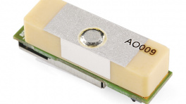
Antenna

It's built in! Housed under the dome of the RTK Facet mosaic is a surveyor grade L1/L2/L5 antenna. This antenna is a unique combination of elements designed to receive the GNSS signals (L1/L2/L5).
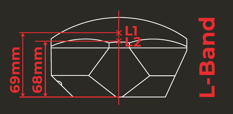
SparkFun RTK Facet mosaic Antenna Reference Points
The built-in antenna has an antenna phase center (APC) of 69mm from the base of the device to the measuring point of the L1 antenna and an APC of 68mm to the measuring point of the L2 antenna.
Internal Battery
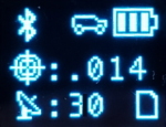
RTK Facet mosaic Display showing three battery bars
The RTK Facet mosaic has a built in 6000mAh battery and consumes approximately 240mA worst case with Bluetooth connection active and GNSS fully tracking. This will allow for around 25 hours of use in the field. If more time is needed in the field a standard USB power bank can be attached. If a 10,000mAh bank is attached one can estimate 56 hours of run time; assuming, 25% of the capacity is lost to efficiencies of the power bank and charge circuit within RTK Facet mosaic.
The RTK Facet mosaic can be charged from any USB port or adapter. The charge circuit is rated for 1000mA, so USB 2.0 ports will charge at 500mA and USB 3.0+ ports will charge at 1A.
To quickly view the state of charge, turn on the unit. The battery icon will indicate the following:
- 3 bars: >75% capacity remain
- 2 bars: >50% capacity remain
- 1 bar: >25% capacity remain
- 0 bars: <25% capacity remain
Display

The display on the front of the RTK Facet mosaic.
The RTK Facet mosaic has a 0.96" high-contrast OLED display. While small, it packs various situational data that can be helpful in the field. Please see the SparkFun RTK Everywhere Firmware Manual for a description of the information being displayed.
Hardware Assembly
The RTK Facet mosaic was designed to work with low-cost, off the shelf equipment. The RTK Facet mosaic is designed to use corrections provided via u-blox's PointPerfect system, therefore, a Base/Rover setup is not needed. However, if the service is not available the RTK Facet mosaic can still be used in a traditional Base/Rover setup. Here we'll describe how to assemble a Rover and Base.
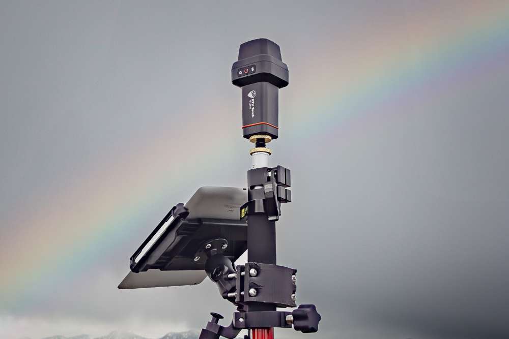
Surveying (Rover Mode)
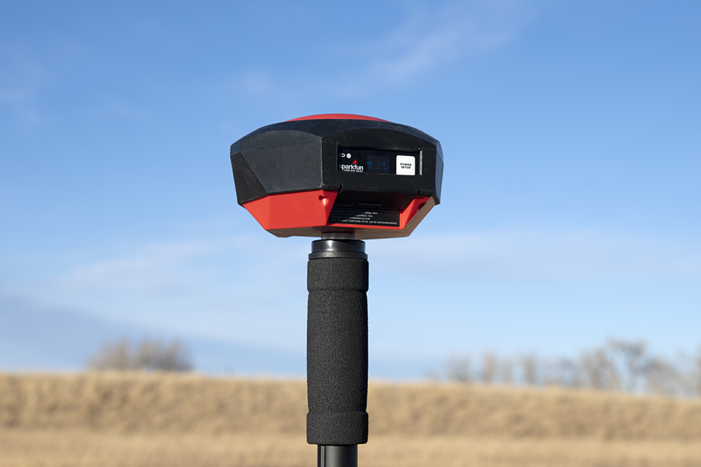
Basic RTK Facet mosaic Rover setup with RTCM over Bluetooth
Shown above is the most common RTK Rover setup. A monopole designed for cameras is used. The ¼” camera thread of the monopole is adapted to ⅝” 11-TPI and the RTK Facet mosaic is mounted on top. No radio is needed because RTCM correction data is provided by a phone over Bluetooth.
Tip
If you're shopping for a monopole (aka monopod), get one that is 65” in length or greater to ensure that the antenna will be above your head. We've had good luck with the Amazon Basics brand.
If you prefer to mount your tablet or cell phone to the monopole be sure to get a clamp that is compatible with the diameter of your monopole and has a knob to increase clamp pressure. Our monopole is 27mm in diameter so a device clamp would need to be able to handle that diameter.
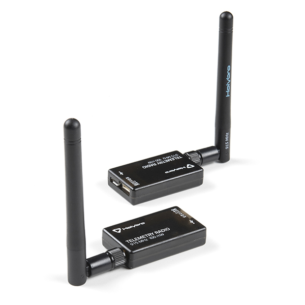
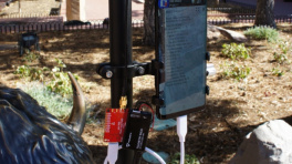
Radio Link
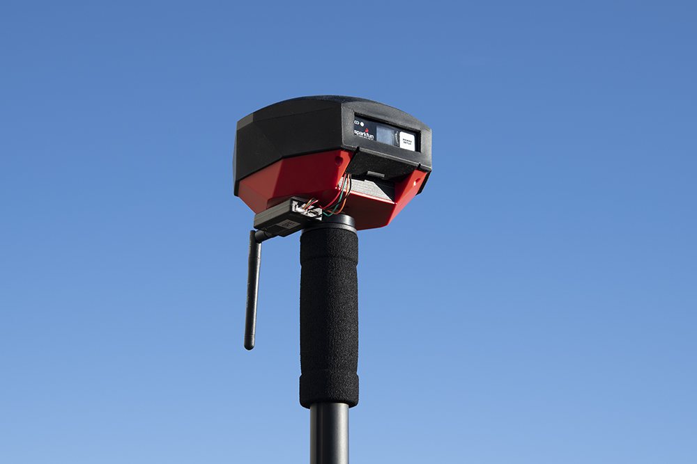
2nd most common setup with a 915MHz Radio providing RTCM
If you are receiving RTCM correction data over a radio link it's recommended that you attach a radio to the bottom of the RTK Facet mosaic.
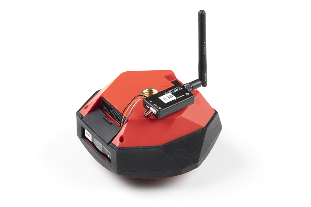
Picture hanging strips from 3M make a nice semi-permanent mount. Plug the 4-pin to 6-pin JST cable included with the RTK Facet mosaic from the Radio port to either of the Serial Telemetry Radios (shipped in pairs). We really love these radios because they are paired out of the box, either can send or receive (so it doesn't matter which radio is attached to base or rover) and they have remarkable range. We achieved over a mile range (nearly 1.5 miles or 2.4km) with the 100mW radios and a big 915MHz antenna on the base (see this tutorial for more info).
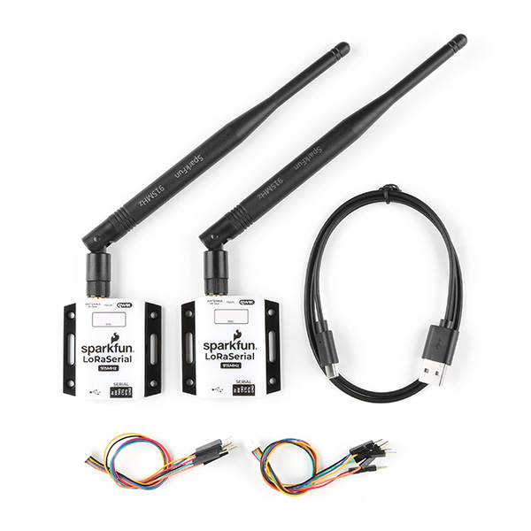
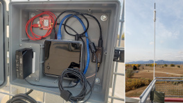
Temporary Base
A temporary or mobile base setup is needed when you are in the field too far away from a correction source and/or cellular reception. A 2nd RTK Facet mosaic is mounted to a tripod and it is configured to complete a survey-in (aka, locate itself), then begin broadcasting RTCM correction data. This data (~1000 bytes a second) is sent to the user's connected radio of choice. For our purposes, the 915MHz 100mW telemetry radios are used because they provide what is basically a serial cable between our base and rover.

Temporary RTK Facet mosaic Base setup
Any tripod with a ¼” camera thread will work. The Amazon Basics tripod works well enough but is a bit light weight and rickety. The ¼” camera thread is adapted to ⅝” 11-TPI and the RTK Facet mosaic is attached on top.
Once the base has been setup with a clear view of the sky, turn on the RTK Facet mosaic. Once on, press the Setup button to put the device in Base mode. The display will show the Survey-In screen for 60-120 seconds. Once the survey is complete the display will show the 'Xmitting' display and begin producing RTCM correction data. You can verify this by viewing the LEDs on the telemetry radio (a small red LED will blink when serial data is received from the RTK Facet mosaic). The RTK Facet mosaic is designed to follow the u-blox recommended survey-in of 60s and a mean 3D standard deviation of 5m of all fixes. If a survey fails to achieve these requirements it will auto-restart after 10 minutes.
Tip
A mobile base station works well for quick trips to the field. However, the survey-in method is not recommended for the highest accuracy measurements because the positional accuracy of the base will directly translate to the accuracy of the rover. Said differently, if your base's calculated position is off by 100cm, so will every reading your rover makes. If you're looking for maximum accuracy consider installing a static base with fixed antenna. We were able to pinpoint the antenna on the top of SparkFun with an incredible accuracy +/-2mm of accuracy using PPP!
Software Overview
USB Drivers
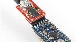
ESP32 (CH340)
In order to interface with the ESP32 module, the USB driver for the CH340 USB-to-Serial converter must be installed. Users can be download the USB driver from the manufacturer's website:
Linux
A USB driver should not be required for most Linux based operating systems; the standard Linux CDC-ACM driver is usually sufficient. However, if necessary, users can try the USB driver below:
CH341SER_LINUX.ZIP
mosaic-X5
In order to interface with the mosaic-X5 on Windows computers, a USB driver must be installed.
-
Windows
The USB driver for the mosaic-X5 module can be installed through two methods:
- RxTools Software Suite (1)
- mosaic-X5 GNSS Receiver Module (2)
- The driver is installed during the installation process.
- The installation file for the Windows USB driver will be available from the mass-storage device when the board is initially connected to the computer.
Having Trouble?
For users who are having trouble installing the USB driver, we have an archived version (v3.0.2) of the installation file. Users can download version 3.0.2 of the driver, by clicking on the button below.
Download USB Driver (v3.0.2) Latest Driver
This driver version was archived at the time that the mosaic-X5 hookup guide was written. Please do not request for the file to be updated.
For the latest USB driver from Septentrio, please install their driver through the RxTools software suite.
Linux
On Linux, the standard Linux CDC-ACM driver is suitable for the mosaic-X5 module.
ESP32
Terminal Emulator
In order to configure the WiFi settings on the ESP32, users will need to install a terminal emulation program on their computer.
For Windows computers, we highly recommend TeraTerm.
Some Linux operating systems will already have the screen terminal emulator preinstalled.
Need Directions?
Check out our hookup guide to install your favorite terminal emulator:
-
Serial Terminal Basics
RTK Everywhere Firmware
System Configuration
Out of the box, the SparkFun RTK products are exceptional GNSS receivers out-of-box and can be used with little or no configuration. Additionally, the line of RTK products from SparkFun are immensely configurable. Please see the SparkFun RTK Everywhere Firmware Manual for detailed descriptions of all the available features on the RTK products
Firmware Updates and Customization
The RTK Facet mosaic is completely open-source meaning you have total access to the firmware code and hardware designs.
From time to time SparkFun will release new firmware for the RTK product line to add and improve functionality. We've made updating the firmware as easy as possible. Please see Updating RTK Firmware for a step by step tutorial.
Bluetooth and NTRIP
The RTK Facet mosaic transmits full NMEA sentences over Bluetooth serial port profile (SPP) at 4Hz and 115200bps. This means that nearly any GIS application that can receive NMEA data over serial port (almost all do) can be used with the RTK Facet mosaic. As long as your device can open a serial port over Bluetooth (also known as SPP) your device can retrieve industry standard NMEA positional data.
Please see the SparkFun RTK Everywhere Firmware Manual for step by step instructions.
mosaic-X5
RxTools Software Suite
Even if you aren't necessarily interested in it, we highly recommend that users install the RXTools software suite before connecting to the mosaic-X5. For Windows PCs, it also includes the USB driver for the module that enables the Ethernet-over-USB support and virtual COM ports.
System Requirements1
- Windows 7
- Windows 8
- Windows 10
- Fedora 23 (or later) using Qt technology.
- The standalone tools (except
bin2asc) will run on older distributions.
- The standalone tools (except
The minimal hardware requirements (1Hz update2):
- CPU: 1 GHz processor
- RAM: 1 GB RAM
- Screen Resolution: 1024×768 or higher resolution
Installation Instructions1
Users can install RxTools software suite by running the installation executable3(1), located in the RxTools\windows directory of the downloaded *.zip file4. During the installation process, users will be notified if a previous version of RxTools is already installed then the previous version will be uninstalled. Next, users will need to provide an installation directory for the RxTools software suite. Users will then select which of the following applications5 are installed:
- For RxTools v22.1.0, the installation filename is
RxTools_22_1_0_Installer.exefor Windows PCs.
- RxControl
- SBF Converter
- SBF Analyzer
- RxLogger
- RxUpgrade
- RxDownload
- RxPlanner
- Data Link
- RxAssistant
- RxLauncher
Warning
It is recommended that users NOT install RxControl as root, for security reasons and to avoid installation overwrites of other system settings. To make RxTools available to more than one user, provide a shared installation directory.
Users can install RxTools software suite by running the installation binary3(1), located in the RxTools/linux-i386/ directory of the downloaded *.zip file4. During the installation, users will be prompted for an installation directory. If there are any previous installations of RxControl, please use a different directory to avoid conflicts.
- For RxTools v22.1.0, the installation filename is
RxTools_22_1_0_Installer.binfor Linux.
Permission Settings
Once installed, users may need to reconfigure their permission settings:
-
RxTools will need rights to access the
/dev/ttyS*serial ports.-
To access the serial ports, users must be part of the
uucpandlockgroups (1). This can be configured by editing the/etc/group6 file and adding the username to the lines defining theuucpgroup and thelockgroup.For example, when adding the user
jsmithto theuucpgroup, users would modify the/etc/groupfile as shown below: -
On Linux machine administered centrally on a local network, ask your system administrator to be included in the
uucpandlockgroups.
-
-
RxTools also needs read/write (
rw) access(4) to the/dev/ttyS*serial ports.-
Users can change the permissions with the
chmod7 command:
-
- On most Linux operating systems, the
/dev/ttyS*devices are owned byrootand belong to theuucpgroup with read/write (rw) access. Additionally, the devices are normally locked by writing a file in the/var/lock/directory, with the same permissions. - Remove
- Replace with this line
- By default, users will normally have read/write (
rw) access to the/dev/ttyS*serial ports. - where users must specify the port number
e.g./dev/ttyS0might be portCOM1
Note
In order for these changes to take effect, users must update their environment by logging out and back in.
Be aware that the X-session has to be restarted as well. On most systems, this can be done by pressing the key combination Ctrl + Alt + Backspace
64-bit OS
In order to run the RxTools on a 64-bit Linux operating system, users might have to install the 32-bit version of the C standard library.
- For Fedora installations, this is the
glibc.i686package. - The equivalent for Debian(/Ubuntu) installations is the
ia32-libspackage.
Web Interface
With the USB driver installed, the mosaic-X5 module supports Ethernet-over-USB. The default IP address allocated for the Ethernet-over-USB interface is 192.168.3.1. This IP can be entered in any browser to open a connection to the receiver's Web Interface as shown below.
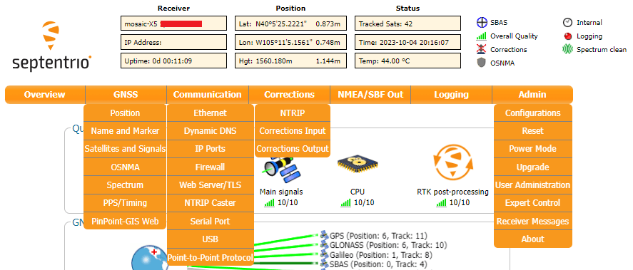
All the drop-down navigation tabs in the web interface.
Info
The default IP address cannot be changed; this feature is only to be used when a single receiver is connected to your computer.
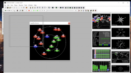
PyGPSClient
As an alternative to GIS apps on mobile devices, for users with computers, we recommend PyGPSClient as an option for viewing the data from the NMEA messages and connecting to an NTRIP caster. However, users should be aware that this GUI interface is currently limited to only receiving UART messages and cannot send messages to configure the mosaic-X5 GNSS module.
Software Limitations
With this software, users will only be able to view the data from the NMEA messages and connect to an NTRIP caster. Users will not be able to configure the mosaic-X5 GNSS module with the built-in console.
Resources
For additional information, users can refer to the following resources for the PyGPSClient software:
Installation
There are a variety of installation methods detailed in the GitHub repository's README.md file. However, we recommend utilizing the pip installation method. Depending on how Python is installed on your computer, one of the following commands should allow users to install the software.
Installation Commands
Tip
This installation method requires an internet connection. Additionally, users will also need administrative privileges (or root access sudo) for the installation.
Connecting to the mosaic-X5
Before users can connect to the SparkPNT RTK Facet mosaic, they will need to specify the settings of the UART port in PyGPSClient. Once configured, users can select the button and PyGPSClient will automatically attempt to connect to the GNSS module.
- Below, is a list of the default settings for
UARTport of the SparkPNT RTK Facet mosaic. These settings should be selected in the configuration menu.

Specify the settings for the UART port in QGNSS.
Default Settings
The UART port of the RTK Facet mosaic will have the following default configuration:
- Baudrate: 115200bps
- Data Bits: 8
- Parity: No
- Stop Bits: 1
- Flow Control: None
Resources
Product Resources
- Product Page
-
Design Files:
-
All Files
-
Connector Board
-
Display Board
-
Main Board
-
-
Component Documentation
-
mosaic-X5
-
ESP32-WROVER-E
-
Miscellaneous
-
- Firmware Repository
- SFE Product Showcase
Additional Resources
🏭 Manufacturer's Resources
-
Septentrio also provides great resources for the mosaic-X5:
- mosaic-X5 Product Page
- Support Portal:
- Septentrio Knowledge Base (1)
- Learn More
- Webinars
- Technical Papers
- Insights (Case Studies and Technical Articles)
- Community
- Agnostic Corrections Program
- GitHub:
- YouTube Channel (2)
- JammerTest 2023 - Anti-Jamming and Anti-Spoofing Performance
-
Recommended Articles
General Knowledge
mosaic - Getting started
Resetting a receiver
Resetting and clearing the non-volatile memory
Generating a diagnostic report of a Septentrio receiver
RTCMv3 messages supported by the Septentrio receivers
Interference Detection, Mitigation, and FlaggingProviding Corrections
How to set up a base station
RTK positioning with a moving baseline
Set up an (internal) NTRIP caster on a Septentrio receiverApplying Corrections
Receive corrections over IP
Receive corrections via NTRIP
Using uBlox's correction services for precise positioningAntenna Corrections
-
Recommended Videos
Getting started with the mosaic receiver module
Output NMEA data on the mosaic receiver module
Receiving NTRIP corrections on the mosaic module
Logging data to the Septentrio mosaic receiver module
Receiving corrections over an IP connection
Share the USB internet connection on your receiver
Septentrio's Agnostic GNSS Corrections program
Test-run for Septentrio's anti-jamming feature
mosaic - GNSS module receiver range from Septentrio
-
Espressif also provides great resources for their ESP32 module:
- ESP32 Product Resource Page
- Espressif's Forum for the ESP32
- Espressif GitHub Repositories
- ESP32 Arduino Core
.jsonfile needed for Epressif's ESP32 Arduino Core:
https://raw.githubusercontent.com/espressif/arduino-esp32/gh-pages/package_esp32_index.json
- ESP-IDF -- IoT Development Framework
- ESP32 Arduino Core
Troubleshooting Tips
Need Help?
If you need technical assistance or more information on a product that is not working as you expected, we recommend heading over to the SparkFun Technical Assistance page for some initial troubleshooting.
If you can't find what you need there, the SparkFun GNSS Forum is a great place to ask questions.
Account Registration Required
If this is your first visit to our forum, you'll need to create a Forum Account to post questions.
Replacement Parts
If you loose and/or damage any part of the RTK Facet mosaic kit, all of our available replacement parts for the kit and hardware component can be found here:
Kit Parts
-
SparkPNT RTK Facet Ruggedized Hardcase
PRT-27115 -
Antenna Thread Adapter - 1/4in. to 5/8in.
PRT-17546 -
JST-GHR-04V to JST-GHR-06V Cable - 1.25mm pitch
CAB-17239 -
Breadboard to JST-GHR-04V Cable - 4-Pin x 1.25mm Pitch
CAB-17240 -
USB-A to USB-C Cable - 3m (Flexible Silicone)
CAB-24060 -
USB A and C Power Delivery (PD) Wall Adapter - 65W
TOL-24059
Components - RTK Facte mosaic
- M2.2-0.98 x 10mm Thread Forming Screws - Phillips Head
- M3-1.34 x 10mm Thread Forming Screws - Phillips Head
-
The system requirements and installation instructions are from the RxTools v22.1.0 user manual. This information may change in later iterations of the software suite. Please refer to the user manual (of the version you are utilizing) for the most accurate information. ↩↩↩
-
Higher data rates will require higher CPU speed and more memory capacity. ↩
-
Users will need administrative privileges to install the RxTools software. ↩↩
-
Users may need to extract the RxTools installation files from the downloaded, compressed file. ↩↩
-
Please see the release notes for the issues and limitations of the RxTools applications. ↩
-
Requires
cprivileges. ↩ -
Changing these permissions also requires
rootprivileges. ↩