Introduction
-
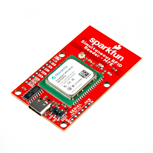
SparkFun Simultaneous RFID Reader - M7E Hecto
SKU: WRL-24738
-
The M7E Hecto is a Ultra-High Frequency (UHF) RFID reader from JADAK© capable of reading multiple tags simultaneously at up to 150 tags per second and can also write data to tags. The M7E Hecto can read tags from several feet away (up to 16 feet in our testing!) with the proper antenna, conditions and device settings. This board includes a USB-C connector and CH340C USB to UART converter to quickly connect the board to a computer and read tags with no soldering required.
Along with the USB-C connector, the Simultaneous RFID Reader 3.3V has a 0.1"-spaced PTH header for connecting it to an external converter or to a 3.3V microcontroller of your choice to use it with the SparkFun Simultaneous RFID Tag Reader Library. A 2-way switch on the board allows for easy switching between the included communication interfaces.
Purchase from SparkFun
In this guide we'll cover everything you need to set up this RFID reader and use it with the Universal Reader Assistant application to read and write to UHF tags. We'll also cover how to set this board up in a circuit with a 3.3V microcontroller and point you to where you can get started using the SparkFun Simultaneous RFID Tag Reader Arduino Library.
Required Materials
We designed this version of the Simultaneous RFID Reader to work over either USB-C or a serial plated through-hole (PTH) connection so depending on your application, you may need different materials.
USB Connection
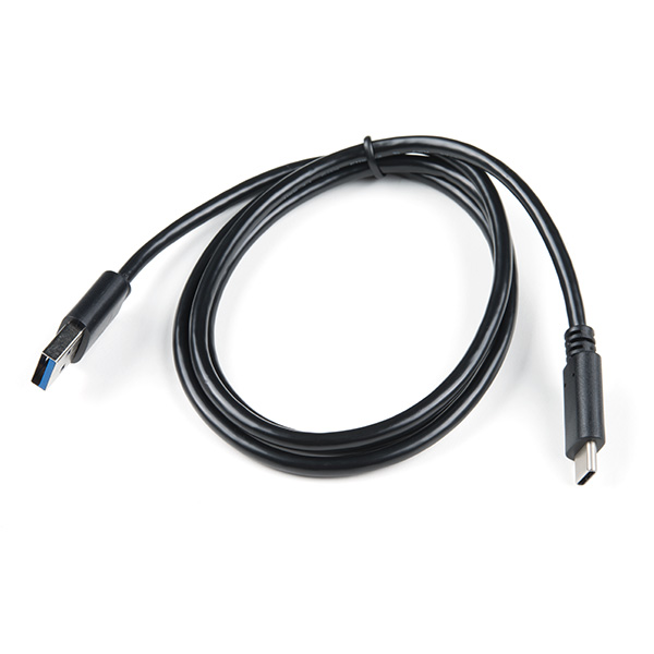
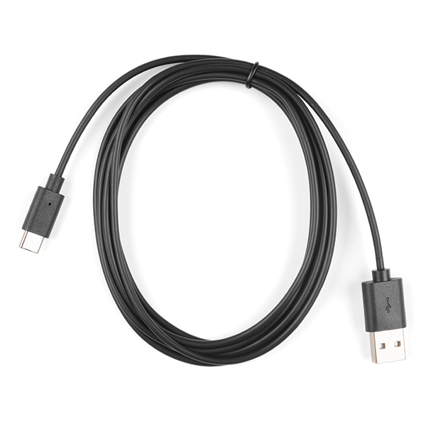
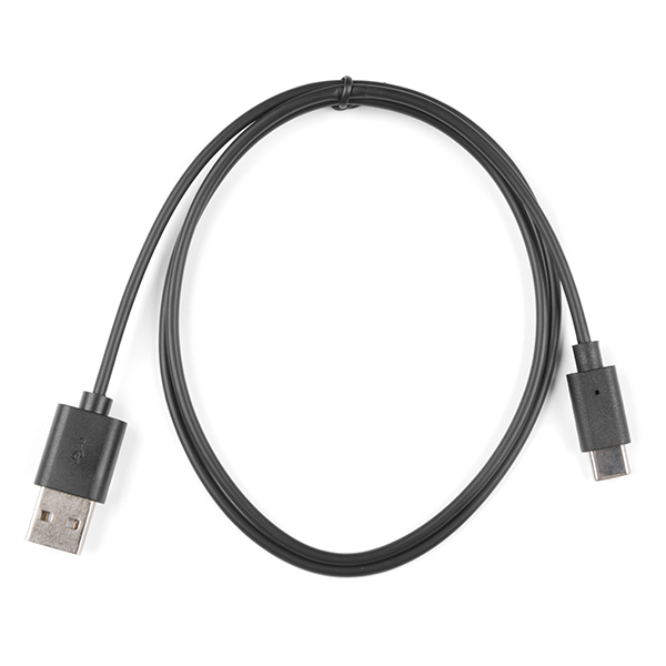
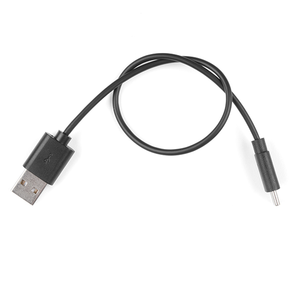
The quickest way to get the RFID Reader up and running is through the USB-C connector. If you opt for this you'll need a USB-C cable like the ones below:
PTH Serial Connection
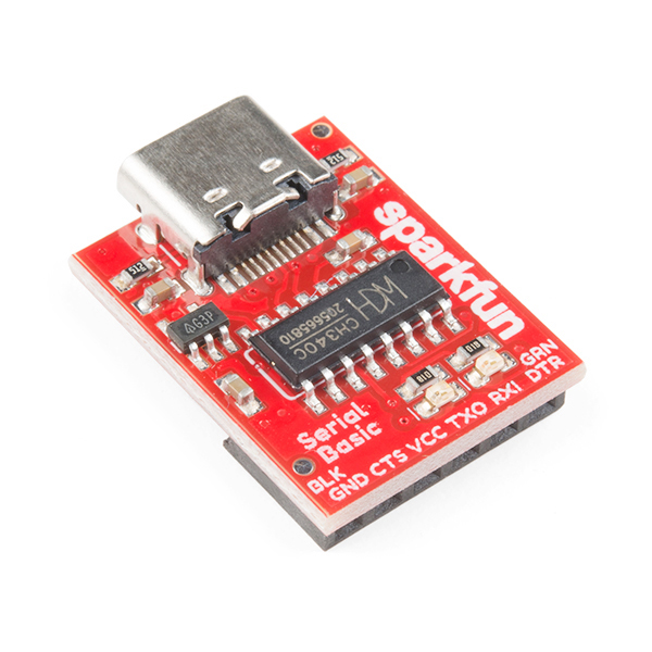
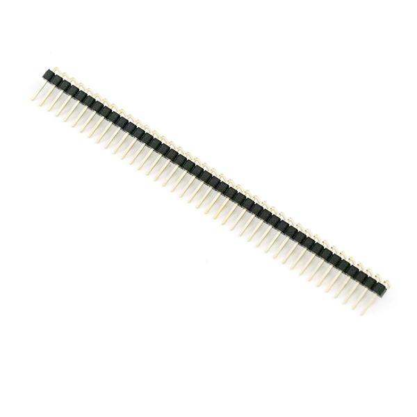
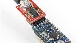
Users who prefer to use the PTH headers to connect to a serial converter or microcontroller will want to solder either wire or a set of header pins to the board to make connections to the external device. If you don't have wire, header pins or soldering tools you may want to add the products below to your cart:
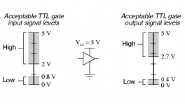
Logic Levels
Note: The serial output on the Simultaneous RFID Reader - M7E operates at 3.3V logic so make sure the microcontroller or serial converter connected to this interface operates at 3.3V or are properly level-shifted.
Additional Materials
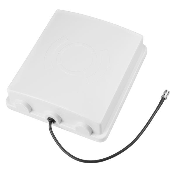
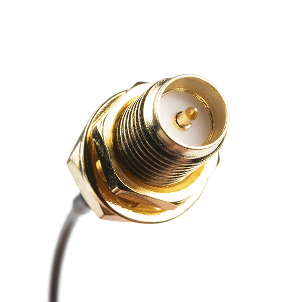
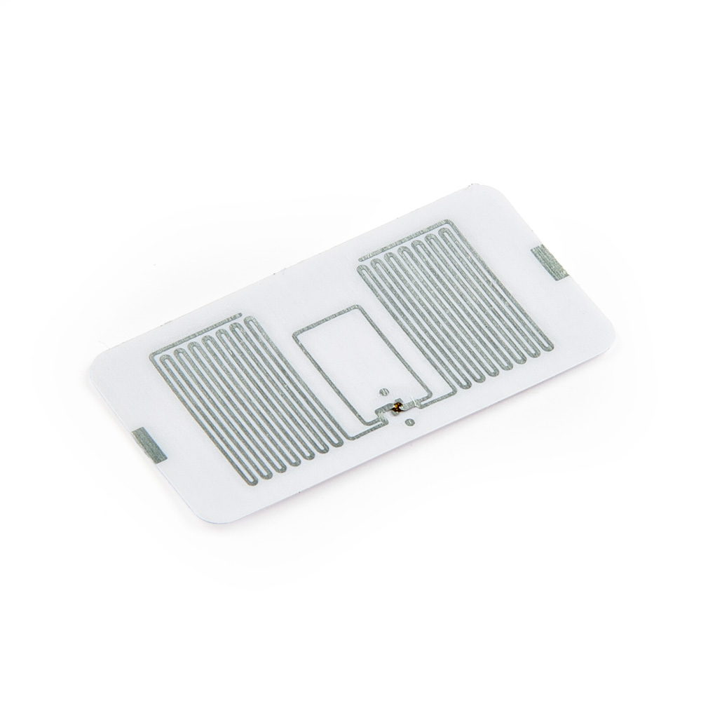
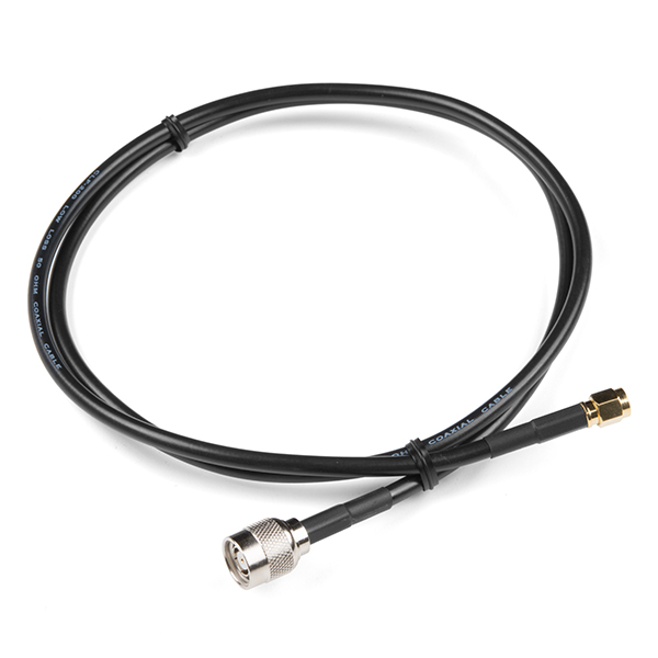
You'll also need UHF RFID tags for the M7E Hecto to read/write. For best range performance you'll need an external antenna along with the appropriate adapter cables. We'll demonstrate how to connect the external antenna using the cables listed below:
Suggested Reading
If you aren't familiar with the following concepts, we recommend reading through these tutorials before continuing with this guide.


Hardware Overview
In this section we'll take a closer look at the hardware present on the Simultaneous RFID Reader 3.3V.
M7E Hecto UHF RFID Reader
The M7E Hecto is an Ultra-High Frequency (UHF) RFID reader capable of reading multiple tags simultaneously at up to 150 tags per second.

The module can also write data quickly to RFID tags with 96-bit EPC (80msec typical write time). The M7E Hecto boasts adjustable read and write RF power levels from 0dBm to 27dBm in 0.01dBm steps and can read tags from several feet away (even more than 16 feet in our testing!) with the proper antenna, conditions and device settings. The M7E-Hecto works with common, low-cost, passive, Gen2 UHF tags available from a variety of online vendors in a variety of shapes and sizes. We offer two types of UHF tags, ones with adhesive backing and ultra-small ones. Both have 64 bytes of user-writable memory.
The M7E accepts a supply voltage between 3.3V and 5.5V and operates normally so long as the module's current draw is below 1A as it includes a built-in protection circuit that allows no more than 1A drawn to prevent damage to the M7E. Therefore, it's recommended to power the M7E with a 5V source to avoid hitting the current limit at higher read/write powers or when the GPIO and Vout lines are supplying current to other devices. Refer to section 5.2 of the M7E User Guide for detailed information on this limit as well as graphs showing typical current draw at various supply voltages as well as power requirements for different power settings.
Communication Interfaces
The board has two options for interacting with the M7E Hecto's serial interface: USB-C and a plated through-hole (PTH) header. The PTH header can connect to a microcontroller or serial converter (running at 3.3V logic or properly level-shifted). The selection switch on the board labeled UART allows users to choose between the two serial interface options. The board also breaks out several of the M7E Hecto's GPIO pins and the Enable pin.

USB-C
The USB-C connector on the board allows for quick use of the M7E Hecto with just a USB-C cable. The board uses a CH340C USB-to-Serial adapter to translate between the M7E's UART and the USB-C connection.
Through-Hole Serial Connection
The board includes a PTH header for serial communication with a 3.3V microcontroller or other device. The header matches the pinout for our Serial Breakouts for easy connection to those devices.
Serial Selection Switch
The two-way switch on the board labled UART allows the user to toggle between the two serial interfaces: USB-C (USB) and the Serial Header (SER).
Enable and GPIO PTHs
The M7E uses an internal DC to DC converter to provide itself with power. When the EN (enable) pin is pulled low the DC/DC converter is turned off and the module does a hard reset. EN can be left unconnected for normal operation.
Warning
Note: The 3.3V pin on this header is not intended as a power source. It connects to the V_OUT pin on the M7E Hecto which can only supply 5mA. It is best used as a voltage reference.
Power LED
The lone LED on the board indicates device power status. Users can disable this LED by severing the PWR jumper. The Power LED receives voltage from the VOUT pin on the M7E Hecto. Driving the EN pin low disables VOUT and can be used to turn this LED off.

Solder Jumpers
The board has three solder jumpers labeled: PWR, VIN SEL, and SHLD. The table below outlines their label, function, default state, and any notes regarding their use.

| Label | Default State | Function | Notes |
|---|---|---|---|
| PWR | CLOSED | Completes Power LED circuit. | Open to disable Power LED. |
| VIN SEL | CLOSED | Nets V_USB, VIN, and VCC together. | Three-way jumper that nets all voltage inputs together. Adjust to isolate any of these voltages from the others (or all three) if needed. |
| SHLD | CLOSED | Ties USB Shield pin to PCB ground plane. | Open to isolate the USB Shield pin from the rest of the board. |
Ground Plane Heatsink
The board has a large ground plane heatsink on the bottom to help dissipate heat generated by the module.

The exposed copper pour allows the connection to a heatsink such as a chassis or block of metal if needed. The M7E has an integrated temperature sensor that will monitor the internal temperature and can disable RF if the module is overheating and keeps it off until the recorded temperature drops back into the safe range (-40°C to +60°C). Attaching a heat sink to the exposed copper pour or adjusting the read power and/or duty cycle can help dissipate heat to prevent this throttling in long-period applications of this board. Refer to the thermal management considerations of this guide or section 5.4 of the M7E User Guide for more information.
Antenna Options
The Hecto M7E is a powerful transmitter capable of outputting up to 27dBm! That's a lot. The board comes with a PCB trace antenna and a u.FL connector for an external antenna connection.

The trace antenna is enabled by default. Adjust the RF resistor to switch the antenna signal to the u.FL connector to use an external antenna. Refer to the Using an External Antenna section of this guide for more information on this assembly step.
Board Dimensions
The board measures 2.40" x 1.40" (60.96mm x 35.56mm) and has four mounting holes that fit a 4-40 screw.

Hardware Assembly - Simple Assembly
In this section we'll cover the two ways to set up the Simultaneous RFID Reader - M7E over both USB-C and connected to a microcontroller for use with the SparkFun Simultaneous RFID Reader Arduino Library.
Communicating via USB-C Serial
The fastest and easiest way to start using the board is through the USB-C connector. Simply plug the board into a computer with a USB-C cable and open up the Universal Reader Assistant.

Reminder, many computer USB ports can only supply ~500mA @5V which limits the power level settings to roughly 20dBm and lower. Running the M7E at higher power levels may require a dedicated power supply.
Communicating via Serial PTH Header
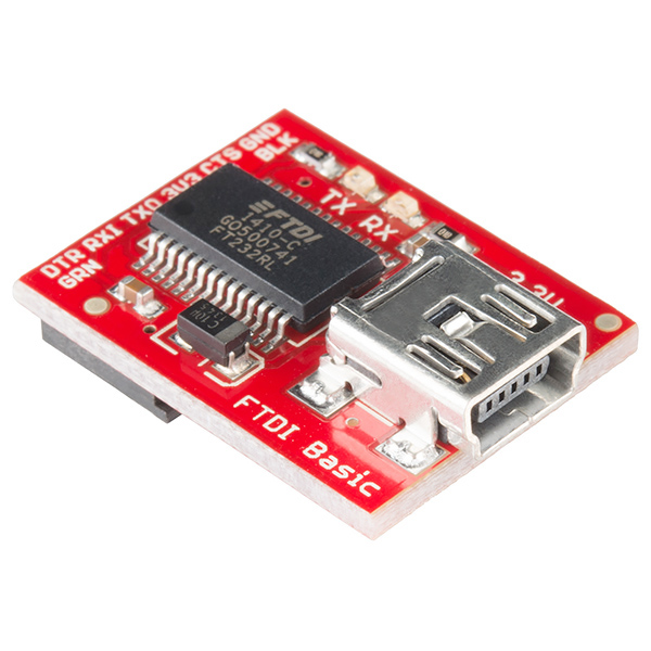
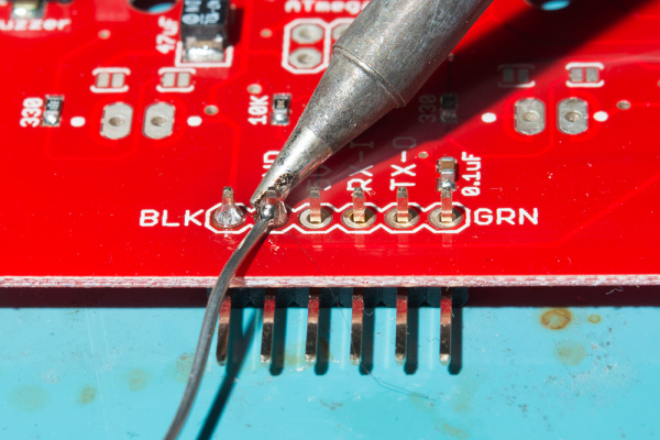
Users who prefer to communicate with the RFID reader using the Serial PTH header should solder either wires or header pins to connect them to a 3.3V microcontroller (you can also use this to connect to a USB UART board like the Serial Basic. If you are not familiar with through-hole soldering or would like a refresher, take a read through this tutorial.

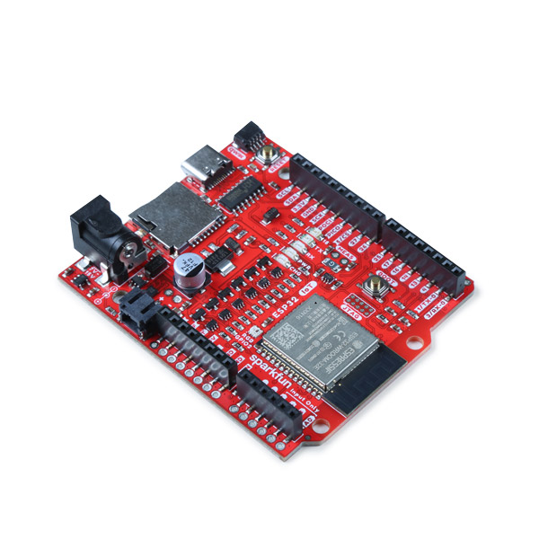
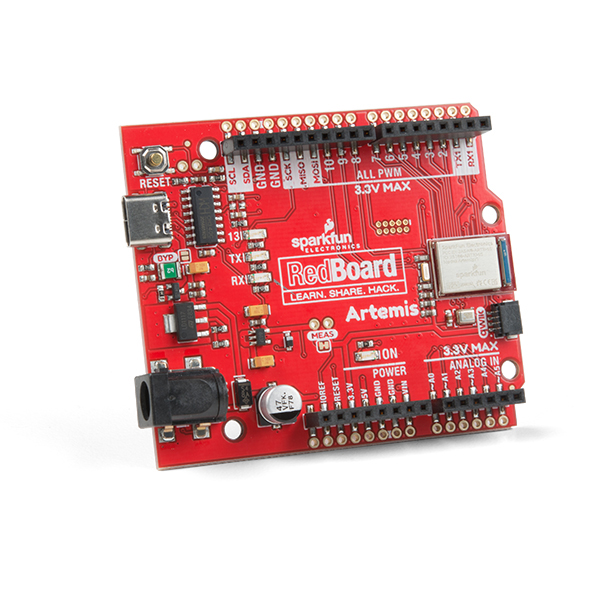
We'll demonstrate soldering male headers to the board and use jumper wires to connect the RFID Reader to the SparkFun RedBoard Artemis for use with the SparkFun Simultaneous RFID Tag Reader Arduino Library.
| RFID Reader | RedBoard Artemis |
|---|---|
| RX | TX / D2 |
| TX | RX / D3 |
| VIN | 5V |
| Ground | Ground |
Digital Pin Selections
Digital pin values are the default selections for Software Serial in the Simulataneous RFID Reader Arduino Library and may be incompatible with your selected microcontroller. Refer to the Arduino Software Serial Reference for pin limitations for common microcontrollers.
Power Supply Considerations
When connecting the Simultaneous RFID Reader - M7E to a microcontroller, make sure your power supply can source sufficient current for your selected power level as the board can draw up to 720mA @5V at max read power level. The M7E's internal voltage regulator includes built-in protection that engages when the current draw reaches 1A and will not allow any more supply current to the module. As such, it is strongly recommended to use a 5V power supply when setting the read power to above +26 dBm.
If you opt to power the RFID Reader from your development board's output voltage we recommend using the 5V out (if applicable) and then powering your development board through a dedicated power supply to avoid browning the circuit out as USB ports can only source ~500mA@5V. The image below shows the Simultaneous RFID Reader - M7E connected to the RedBoard IoT and powered with a dedicated power supply through the barrel jack.
Hardware Assembly - Using an External Antenna
The integrated PCB antenna works well over short distances but users who want to get the maximum range for the M7E Hecto should consider using an external antenna. Connecting an external antenna to the Simultaneous RFID Reader - M7E requires some hardware adjustments, minor assembly steps and other considerations regarding the antenna. Let's go over these adjustments and considerations.
FCC Regulations
From section 5.8 of the M7E Hecto User Guide:
No additional transmitter-compliance testing is required if the module is operated with the same type of antenna as listed in the FCC filing, as long as it has equal or lower gain than the antenna listed. Equivalent antennas must be of the same general type (e.g. dipole, circularly polarized patch, etc.), and must have similar in-band and out-of-band characteristics (consult specification sheet for cutoff frequencies).
The board's PCB trace antenna is a patch antenna with a much lower gain than the list of approved antennas which allows the use of an unmodified board in the field without additional FCC testing.
The u.FL connector allows users to connect higher-gain directional antennas. However, there are stipulations as to what external antennas can be used and additional FCC certifications may be required.
Info
Note: The onboard PCB antenna complies with the FCC regulation.
The list below from section 5.7 of the M7E Hecto User Guide outlines antennas ThingMagic has tested and gotten approved by the FCC. You may use a different antenna from the ones in the list but it must be of equal or less gain than an antenna previously authorized under the same FCC ID and must have similar in-band and out-of0band characteristics (consult specification sheet for cut-off frequencies) if used in a product without additional testing.

Attaching the External Antenna
Switching to the external antenna connection requires changing the position of the antenna (labeled RF) resistor to route the M7E's antenna signal to the u.FL connector on the board.
Adjusting from PCB Antenna to u.FL Connection
Note: You do not need an external antenna for basic use of the Simultaneous RFID Reader - M7E but the PCB antenna reads tags reliably at only up to a few inches away at the highest read power and with the PCB antenna positioned away from any solid surfaces. If you want to take advantage of the full range, follow the steps below to modify the board and enable the u.FL connector for an external antenna connection.
If you have never worked with surface mount components, we recommend reading through these tutorials:
Carefully reflow the 0kΩ resistor labeled RF to move it to the u.FL position. You can either use a soldering iron or hot-air rework station to reflow the solder holding the resistor into place. The photo below shows the RF resistor after adjusting it to the u.FL position.

Next, attach the u.FL to the RP-SMA connector cable. Because this connector is fragile we recommend either taping or hot gluing the sheath of the cable to the PCB. This will help prevent damage to the u.FL connector in case the cable gets pulled on.

To get the best range we recommend attaching an external high-gain antenna to a tripod of some sort. If you only have a desk, that's ok too.

We used the included hardware with the antenna to attach it to the leg of the tripod.

Now connect the RP-SMA to RP-TNC cable. And finally, connect the RP-TNC to the external antenna. You can use a different UHF RFID antenna but you will need to have the correct connectors and cables to go from the u.FL connector on the board to the connector on your specific antenna.

Warning
Don't Forget! Ensure that personnel do not stand in the radiation beam of the antenna unless they are more than 21cm away from the face of the antenna (to adhere to FCC limits for long-term exposure). Refer to the M7E Hecto design guide for more information.
Hardware Assembly - Thermal Management Considerations
The module can reach temperatures greater than 85°C (185°F) when operating at full read power over extended periods so thermal management is an important consideration using this board.
The module will automatically throttle itself to prevent permanent damage from heat. This board provides enough ground plane heatsinking to allow the module to operate at full read power for tens of minutes before throttling occurs. If you plan to operate the module at full power for extended periods (over an hour) we recommend attaching a heatsink.
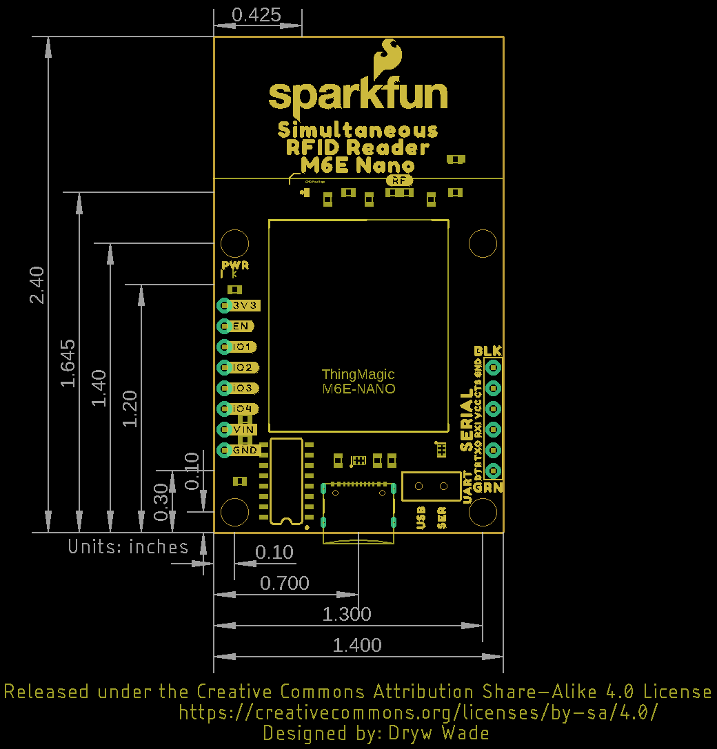
You can get the 1:1 dimensional drawing of the board here. The dimensional drawing below shows the exposed thermal pad and mounting holes.
Heatsinking won’t be required in most prototyping applications. However, if you have heat-sensitive items near the module (such as temperature or humidity sensors) they may be influenced by the module. If you are planning to install the module for long-term operation we recommend attaching a heatsink with thermal compound for best results.
The module also supports changing the read duty cycle to reduce heat dissipation as well. Refer to the M7E-Hecto Design Guide for more information.
Using the ThingMagic Universal Reader Assistant
Start by downloading the Universal Reader Assistant (URA). 32-bit and 64-bit versions are available.
Open the installer once downloading finishes and follow the installation wizard instructions.
Universal Reader Assistant Setup Wizard
Make sure the Simultaneous RFID Reader is plugged in either over USB or through the Serial Header to a USB-to-Serial converter with the UART selection switch in the correct position, and open the Universal Reader Assistant. You should be greeted by the Connection Wizard menu to select the reader type and port:

You can skip this selection and move on to the main menu of the Universal Reader Assistant. Otherwise, select the port your Simultaneous RFID Reader is on and click "Next" and the Connection Wizard should show you the RFID reader settings:

Click either "Connect & Read" or "Connect" to open up the Universal Reader Assistant main window.
Universal Reader Assistant Main Window
The main window of the Universal Reader Assistant contains a whole bunch of settings and status menus to adjust everything from the M7E's read/write options, power level and even perform firmware updates. It also has a handy readout for the M7E's internal temperature along with multiple tabs for interacting with tags the M7E sees including simple tag data, writing to the user memory and also locking a tag with a custom password.
There are a ton of features to the M7E from ThingMagic. Poke around the Universal Reader Assistant to learn more. Write EPC and User Memory are two of the most commonly used tabs.
Info
Note: The ‘Transport Logging’ checkbox is very handy. Select this box and all the serial communication will be recorded to a log file. These HEX bytes can be deciphered and recreated using an Arduino or other microcontroller if you need a particular capability or feature that is not supported in the SparkFun Simultaneous RFID Reader Arduino library.
Thermal Throttling
If you see this window pop up it means the module is reporting a temperature-limit fault condition. The module has an internal temperature sensor and will protect itself from permanent damage. You’ll need to lower your read power or add heatsinking. See the previous section of this guide, Thermal Considerations, for more information.
SparkFun Simultaneous RFID Reader Arduino Library - Library Setup
Attention
If this is your first time using Arduino, please read through our tutorial on installing the Arduino IDE. If you have not installed an Arduino library before, we recommend you check out our installation guide.
The SparkFun Simultaneous RFID Tag Reader Arduino library, while originally written for the M6E-NANO, works just as well for the M7E-HECTO on this RFID Reader breakout. The library handles all serial communication, byte manipulations, and CRC verifications making it easy to quickly get started using the board. Users can download and install the library through the Arduino Library Manager by searching for "SparkFun Simultaneous RFID" and selecting the latest version. If you prefer to manually install the library, download a ZIP of it by clicking the button below:
With the library installed, let's take a closer look at some of the examples included in it. You can take a look at them by navigating to File > Examples > SparkFun Simultaneous RFID Tag Reader Library > Examples.
SparkFun Simultaneous RFID Reader Arduino Library - Arduino Examples
Let's take an in-depth look at most of the examples included in the SparkFun Simultaneous RFID Reader Arduino Library.
UART Switch Position & Software Serial
Make sure the Serial Selection Switch is in the "SER" position when using this library. All of the examples in this Arduino library use the Software Serial Library so if you are not using the SparkFun RedBoard IoT and following the assembly instructions in the Hardware Assembly section, make sure to connect the RX/TX pins on the SER header to compatible pins on your chosen development board. Note, this library
Code to Note
The latest version of the Simultaneous RFID Reader Library has a couple of settings to take note of and adjust accordingly depending on your hardware and setup.
Serial Selection (Software vs Hardware)
If you're using a development board that supports Software Serial, uncomment the following lines and adjust the pins for RX/TX if necessary:
The next option selects which type of serial is used. The code lists a couple of examples for both software serial and hardware so adjust the definition as needed. For example, if you're using a software serial library, define this as softserial. If you're using a hardware serial port on your development board, select the serial port (eg. Serial1) as shown below:
// #define rfidSerial softSerial // Software serial (eg. Arudino Uno or SparkFun RedBoard)
#define rfidSerial Serial1 // Hardware serial (eg. ESP32 or Teensy)
Baud Rate Selection
Next, you'll want to define the baud rate for rfidBaud. We recommend using the settings shown below with 38400 when using software serial and 115200 when using hardware serial:
Module Selection
Since this library supports both the M6E Nano and M7E Hecto, you'll need to define which module you are using. Adjust or comment/uncomment the moduleType definition to set it to the correct module:
Example 1 - Constant Read
The first example sets the M7E to constantly scan and report any tags it sees in the vicinity. Open the example by navigating to File > Examples > SparkFun Simultaneous RFID Reader Library > Example 1 Constant Read. Select your Board and Port and click the "Upload" button. Once the code finishes uploading, open the serial monitor with the baud set to 115200.
Example 1 - Constant Read
/*
Reading multiple RFID tags, simultaneously!
By: Nathan Seidle @ SparkFun Electronics
Date: October 3rd, 2016
https://github.com/sparkfun/Simultaneous_RFID_Tag_Reader
Constantly reads and outputs any tags heard
If using the Simultaneous RFID Tag Reader (SRTR) shield, make sure the serial slide
switch is in the 'SW-UART' position
*/
// Library for controlling the RFID module
#include "SparkFun_UHF_RFID_Reader.h"
// Create instance of the RFID module
RFID rfidModule;
// By default, this example assumes software serial. If your platform does not
// support software serial, you can use hardware serial by commenting out these
// lines and changing the rfidSerial definition below
#include <SoftwareSerial.h>
SoftwareSerial softSerial(2, 3); //RX, TX
// Here you can specify which serial port the RFID module is connected to. This
// will be different on most platforms, so check what is needed for yours and
// adjust the definition as needed. Some examples are provided below
#define rfidSerial softSerial // Software serial (eg. Arudino Uno or SparkFun RedBoard)
// #define rfidSerial Serial1 // Hardware serial (eg. ESP32 or Teensy)
// Here you can select the baud rate for the module. 38400 is recommended if
// using software serial, and 115200 if using hardware serial.
#define rfidBaud 38400
// #define rfidBaud 115200
// Here you can select which module you are using. This library was originally
// written for the M6E Nano only, and that is the default if the module is not
// specified. Support for the M7E Hecto has since been added, which can be
// selected below
#define moduleType ThingMagic_M6E_NANO
// #define moduleType ThingMagic_M7E_HECTO
void setup()
{
Serial.begin(115200);
while (!Serial); //Wait for the serial port to come online
if (setupRfidModule(rfidBaud) == false)
{
Serial.println(F("Module failed to respond. Please check wiring."));
while (1); //Freeze!
}
rfidModule.setRegion(REGION_NORTHAMERICA); //Set to North America
rfidModule.setReadPower(500); //5.00 dBm. Higher values may caues USB port to brown out
//Max Read TX Power is 27.00 dBm and may cause temperature-limit throttling
Serial.println(F("Press a key to begin scanning for tags."));
while (!Serial.available()); //Wait for user to send a character
Serial.read(); //Throw away the user's character
rfidModule.startReading(); //Begin scanning for tags
}
void loop()
{
if (rfidModule.check() == true) //Check to see if any new data has come in from module
{
byte responseType = rfidModule.parseResponse(); //Break response into tag ID, RSSI, frequency, and timestamp
if (responseType == RESPONSE_IS_KEEPALIVE)
{
Serial.println(F("Scanning"));
}
else if (responseType == RESPONSE_IS_TAGFOUND)
{
//If we have a full record we can pull out the fun bits
int rssi = rfidModule.getTagRSSI(); //Get the RSSI for this tag read
long freq = rfidModule.getTagFreq(); //Get the frequency this tag was detected at
long timeStamp = rfidModule.getTagTimestamp(); //Get the time this was read, (ms) since last keep-alive message
byte tagEPCBytes = rfidModule.getTagEPCBytes(); //Get the number of bytes of EPC from response
Serial.print(F(" rssi["));
Serial.print(rssi);
Serial.print(F("]"));
Serial.print(F(" freq["));
Serial.print(freq);
Serial.print(F("]"));
Serial.print(F(" time["));
Serial.print(timeStamp);
Serial.print(F("]"));
//Print EPC bytes, this is a subsection of bytes from the response/msg array
Serial.print(F(" epc["));
for (byte x = 0 ; x < tagEPCBytes ; x++)
{
if (rfidModule.msg[31 + x] < 0x10) Serial.print(F("0")); //Pretty print
Serial.print(rfidModule.msg[31 + x], HEX);
Serial.print(F(" "));
}
Serial.print(F("]"));
Serial.println();
}
else if (responseType == ERROR_CORRUPT_RESPONSE)
{
Serial.println("Bad CRC");
}
else if (responseType == RESPONSE_IS_HIGHRETURNLOSS)
{
Serial.println("High return loss, check antenna!");
}
else
{
//Unknown response
Serial.println("Unknown error");
}
}
}
//Gracefully handles a reader that is already configured and already reading continuously
//Because Stream does not have a .begin() we have to do this outside the library
boolean setupRfidModule(long baudRate)
{
rfidModule.begin(rfidSerial, moduleType); //Tell the library to communicate over serial port
//Test to see if we are already connected to a module
//This would be the case if the Arduino has been reprogrammed and the module has stayed powered
rfidSerial.begin(baudRate); //For this test, assume module is already at our desired baud rate
delay(100); //Wait for port to open
//About 200ms from power on the module will send its firmware version at 115200. We need to ignore this.
while (rfidSerial.available())
rfidSerial.read();
rfidModule.getVersion();
if (rfidModule.msg[0] == ERROR_WRONG_OPCODE_RESPONSE)
{
//This happens if the baud rate is correct but the module is doing a ccontinuous read
rfidModule.stopReading();
Serial.println(F("Module continuously reading. Asking it to stop..."));
delay(1500);
}
else
{
//The module did not respond so assume it's just been powered on and communicating at 115200bps
rfidSerial.begin(115200); //Start serial at 115200
rfidModule.setBaud(baudRate); //Tell the module to go to the chosen baud rate. Ignore the response msg
rfidSerial.begin(baudRate); //Start the serial port, this time at user's chosen baud rate
delay(250);
}
//Test the connection
rfidModule.getVersion();
if (rfidModule.msg[0] != ALL_GOOD)
return false; //Something is not right
//The module has these settings no matter what
rfidModule.setTagProtocol(); //Set protocol to GEN2
rfidModule.setAntennaPort(); //Set TX/RX antenna ports to 1
return true; //We are ready to rock
}
The code attempts to set up the module with the defined baud rate and if that fails, it prints "Module failed to respond. Please check wiring" If you see this prompt, double-check your connections to your development board and retry. On successful module startup and setup, the code prints "Press a key to begin scanning for tags." Send any key message and the M7E will begin to scan for any tags in range and print out their EPC as the screenshot below shows:

Example 2 - Read EPC
The second example demonstrates how to perform a single-shot read of one tag in the reader's range and print out the EPC value over serial. This example uses the .readTagEPC() function to pass it an array of bytes (in almost all cases EPCs are 12 bytes), the size of the array (12), and the amount of time to scan before giving up (500ms is default). This returns RESPONSE_SUCCESS when the M7E detects a tag and stores the EPC in the array given.
Example 2 - Read EPC
/*
  Reading multiple RFID tags, simultaneously!
  By: Nathan Seidle @ SparkFun Electronics
  Date: October 3rd, 2016
  https://github.com/sparkfun/Simultaneous_RFID_Tag_Reader

  Single shot read - Ask the reader to tell us what tags it currently sees. And it beeps!

  If using the Simultaneous RFID Tag Reader (SRTR) shield, make sure the serial slide
  switch is in the 'SW-UART' position.
*/

// Library for controlling the RFID module
#include "SparkFun_UHF_RFID_Reader.h"

// Create instance of the RFID module
RFID rfidModule;

// By default, this example assumes software serial. If your platform does not
// support software serial, you can use hardware serial by commenting out these
// lines and changing the rfidSerial definition below
#include <SoftwareSerial.h>
SoftwareSerial softSerial(2, 3); //RX, TX

// Here you can specify which serial port the RFID module is connected to. This
// will be different on most platforms, so check what is needed for yours and
// adjust the definition as needed. Some examples are provided below
#define rfidSerial softSerial // Software serial (eg. Arudino Uno or SparkFun RedBoard)
// #define rfidSerial Serial1 // Hardware serial (eg. ESP32 or Teensy)

// Here you can select the baud rate for the module. 38400 is recommended if
// using software serial, and 115200 if using hardware serial.
#define rfidBaud 38400
// #define rfidBaud 115200

// Here you can select which module you are using. This library was originally
// written for the M6E Nano only, and that is the default if the module is not
// specified. Support for the M7E Hecto has since been added, which can be
// selected below
#define moduleType ThingMagic_M6E_NANO
// #define moduleType ThingMagic_M7E_HECTO

#define BUZZER1 9
//#define BUZZER1 0 //For testing quietly
#define BUZZER2 10

void setup()
{
  Serial.begin(115200);

  pinMode(BUZZER1, OUTPUT);
  pinMode(BUZZER2, OUTPUT);

  digitalWrite(BUZZER2, LOW); //Pull half the buzzer to ground and drive the other half.

  while (!Serial);
  Serial.println();
  Serial.println("Initializing...");

  if (setupRfidModule(rfidBaud) == false)
  {
    Serial.println("Module failed to respond. Please check wiring.");
    while (1); //Freeze!
  }

  rfidModule.setRegion(REGION_NORTHAMERICA); //Set to North America

  rfidModule.setReadPower(500); //5.00 dBm. Higher values may cause USB port to brown out
  //Max Read TX Power is 27.00 dBm and may cause temperature-limit throttling
}

void loop()
{
  Serial.println(F("Press a key to scan for a tag"));
  while (!Serial.available()); //Wait for user to send a character
  Serial.read(); //Throw away the user's character

  byte myEPC[12]; //Most EPCs are 12 bytes
  byte myEPClength;
  byte responseType = 0;

  while (responseType != RESPONSE_SUCCESS)//RESPONSE_IS_TAGFOUND)
  {
    myEPClength = sizeof(myEPC); //Length of EPC is modified each time .readTagEPC is called

    responseType = rfidModule.readTagEPC(myEPC, myEPClength, 500); //Scan for a new tag up to 500ms
    Serial.println(F("Searching for tag"));
  }

  //Beep! Piano keys to frequencies: http://www.sengpielaudio.com/KeyboardAndFrequencies.gif
  tone(BUZZER1, 2093, 150); //C
  delay(150);
  tone(BUZZER1, 2349, 150); //D
  delay(150);
  tone(BUZZER1, 2637, 150); //E
  delay(150);

  //Print EPC
  Serial.print(F(" epc["));
  for (byte x = 0 ; x < myEPClength ; x++)
  {
    if (myEPC[x] < 0x10) Serial.print(F("0"));
    Serial.print(myEPC[x], HEX);
    Serial.print(F(" "));
  }
  Serial.println(F("]"));
}

//Gracefully handles a reader that is already configured and already reading continuously
//Because Stream does not have a .begin() we have to do this outside the library
boolean setupRfidModule(long baudRate)
{
  rfidModule.begin(rfidSerial, moduleType); //Tell the library to communicate over serial port

  //Test to see if we are already connected to a module
  //This would be the case if the Arduino has been reprogrammed and the module has stayed powered
  rfidSerial.begin(baudRate); //For this test, assume module is already at our desired baud rate
  delay(100); //Wait for port to open

  //About 200ms from power on the module will send its firmware version at 115200. We need to ignore this.
  while (rfidSerial.available())
    rfidSerial.read();

  rfidModule.getVersion();

  if (rfidModule.msg[0] == ERROR_WRONG_OPCODE_RESPONSE)
  {
    //This happens if the baud rate is correct but the module is doing a ccontinuous read
    rfidModule.stopReading();

    Serial.println(F("Module continuously reading. Asking it to stop..."));

    delay(1500);
  }
  else
  {
    //The module did not respond so assume it's just been powered on and communicating at 115200bps
    rfidSerial.begin(115200); //Start serial at 115200

    rfidModule.setBaud(baudRate); //Tell the module to go to the chosen baud rate. Ignore the response msg

    rfidSerial.begin(baudRate); //Start the serial port, this time at user's chosen baud rate

    delay(250);
  }

  //Test the connection
  rfidModule.getVersion();
  if (rfidModule.msg[0] != ALL_GOOD)
    return false; //Something is not right

  //The module has these settings no matter what
  rfidModule.setTagProtocol(); //Set protocol to GEN2

  rfidModule.setAntennaPort(); //Set TX/RX antenna ports to 1

  return true; //We are ready to rock
}

Note, this example also includes definitions and code to set up and use the buzzer found on the Simultaneous RFID Reader - M6E Nano which is not present on the Simultaneous RFID Reader - M7E though users can wire a buzzer like this for an audio feedback when a tag is scanned.
Example 3 - Write EPC
Example 3 shows how to write a character string and store it as a custom EPC value. This is a great way to keep track of which tag is which by setting the EPC to something like WRENCH or PILL#317. Note, EPCs can only be written in an even number of bytes like the example sets it to:
Example 3 - Write EPC
/*
  Reading multiple RFID tags, simultaneously!
  By: Nathan Seidle @ SparkFun Electronics
  Date: October 3rd, 2016
  https://github.com/sparkfun/Simultaneous_RFID_Tag_Reader

  Write a new EPC (Electronic Product Code) to a tag
  This is a good way to assign your own, easy to read ID to a tag.
  Most tags have 12 bytes available for EPC

  EPC is good for things like UPC (this is a gallon of milk)
  User data is a good place to write things like the milk's best by date
*/

// Library for controlling the RFID module
#include "SparkFun_UHF_RFID_Reader.h"

// Create instance of the RFID module
RFID rfidModule;

// By default, this example assumes software serial. If your platform does not
// support software serial, you can use hardware serial by commenting out these
// lines and changing the rfidSerial definition below
#include <SoftwareSerial.h>
SoftwareSerial softSerial(2, 3); //RX, TX

// Here you can specify which serial port the RFID module is connected to. This
// will be different on most platforms, so check what is needed for yours and
// adjust the definition as needed. Some examples are provided below
#define rfidSerial softSerial // Software serial (eg. Arudino Uno or SparkFun RedBoard)
// #define rfidSerial Serial1 // Hardware serial (eg. ESP32 or Teensy)

// Here you can select the baud rate for the module. 38400 is recommended if
// using software serial, and 115200 if using hardware serial.
#define rfidBaud 38400
// #define rfidBaud 115200

// Here you can select which module you are using. This library was originally
// written for the M6E Nano only, and that is the default if the module is not
// specified. Support for the M7E Hecto has since been added, which can be
// selected below
#define moduleType ThingMagic_M6E_NANO
// #define moduleType ThingMagic_M7E_HECTO

void setup()
{
  Serial.begin(115200);

  while (!Serial);
  Serial.println();
  Serial.println("Initializing...");

  if (setupRfidModule(rfidBaud) == false)
  {
    Serial.println("Module failed to respond. Please check wiring.");
    while (1); //Freeze!
  }

  rfidModule.setRegion(REGION_NORTHAMERICA); //Set to North America

  rfidModule.setReadPower(500); //5.00 dBm. Higher values may cause USB port to brown out
  //Max Read TX Power is 27.00 dBm and may cause temperature-limit throttling

  rfidModule.setWritePower(500); //5.00 dBm. Higher values may cause USB port to brown out
  //Max Write TX Power is 27.00 dBm and may cause temperature-limit throttling
}

void loop()
{
  Serial.println(F("Get all tags out of the area. Press a key to write EPC to first detected tag."));
  if (Serial.available()) Serial.read(); //Clear any chars in the incoming buffer (like a newline char)
  while (!Serial.available()); //Wait for user to send a character
  Serial.read(); //Throw away the user's character

  //"Hello" Does not work. "Hell" will be recorded. You can only write even number of bytes
  //char stringEPC[] = "Hello!"; //You can only write even number of bytes
  //byte responseType = nano.writeTagEPC(stringEPC, sizeof(stringEPC) - 1); //The -1 shaves off the \0 found at the end of string

  char hexEPC[] = {0xFF, 0x2D, 0x03, 0x54}; //You can only write even number of bytes
  byte responseType = rfidModule.writeTagEPC(hexEPC, sizeof(hexEPC));

  if (responseType == RESPONSE_SUCCESS)
    Serial.println("New EPC Written!");
  else
    Serial.println("Failed write");
}

//Gracefully handles a reader that is already configured and already reading continuously
//Because Stream does not have a .begin() we have to do this outside the library
boolean setupRfidModule(long baudRate)
{
  rfidModule.begin(rfidSerial, moduleType); //Tell the library to communicate over serial port

  //Test to see if we are already connected to a module
  //This would be the case if the Arduino has been reprogrammed and the module has stayed powered
  rfidSerial.begin(baudRate); //For this test, assume module is already at our desired baud rate
  delay(100); //Wait for port to open

  //About 200ms from power on the module will send its firmware version at 115200. We need to ignore this.
  while (rfidSerial.available())
    rfidSerial.read();

  rfidModule.getVersion();

  if (rfidModule.msg[0] == ERROR_WRONG_OPCODE_RESPONSE)
  {
    //This happens if the baud rate is correct but the module is doing a ccontinuous read
    rfidModule.stopReading();

    Serial.println(F("Module continuously reading. Asking it to stop..."));

    delay(1500);
  }
  else
  {
    //The module did not respond so assume it's just been powered on and communicating at 115200bps
    rfidSerial.begin(115200); //Start serial at 115200

    rfidModule.setBaud(baudRate); //Tell the module to go to the chosen baud rate. Ignore the response msg

    rfidSerial.begin(baudRate); //Start the serial port, this time at user's chosen baud rate

    delay(250);
  }

  //Test the connection
  rfidModule.getVersion();
  if (rfidModule.msg[0] != ALL_GOOD)
    return false; //Something is not right

  //The module has these settings no matter what
  rfidModule.setTagProtocol(); //Set protocol to GEN2

  rfidModule.setAntennaPort(); //Set TX/RX antenna ports to 1

  return true; //We are ready to rock
}
char stringEPC[] = "Hello!"; //You can only write even number of bytes
byte responseType = nano.writeTagEPC(stringEPC, sizeof(stringEPC) - 1); //The -1 shaves off the \0 found at the end of string
setWritePower(). This sets the power level when writing to a tag similar to setReadPower so it can be boosted up to the same values as read power.
nano.setWritePower(500); //5.00 dBm. Higher values may cause USB port to brown out
//Max Write TX Power is 27.00 dBm and may cause temperature-limit throttling
Examples 4 & 5 - Read/Write User Data
Example 4 shows how to detect and read a tag's available user memory. Not all UHF RFID tags have user memory and may not be configurable.
Example 4 - Read User Data
/*
  Reading multiple RFID tags, simultaneously!
  By: Nathan Seidle @ SparkFun Electronics
  Date: October 3rd, 2016
  https://github.com/sparkfun/Simultaneous_RFID_Tag_Reader

  Read the user writeable data from a detected tag
*/

// Library for controlling the RFID module
#include "SparkFun_UHF_RFID_Reader.h"

// Create instance of the RFID module
RFID rfidModule;

// By default, this example assumes software serial. If your platform does not
// support software serial, you can use hardware serial by commenting out these
// lines and changing the rfidSerial definition below
#include <SoftwareSerial.h>
SoftwareSerial softSerial(2, 3); //RX, TX

// Here you can specify which serial port the RFID module is connected to. This
// will be different on most platforms, so check what is needed for yours and
// adjust the definition as needed. Some examples are provided below
#define rfidSerial softSerial // Software serial (eg. Arudino Uno or SparkFun RedBoard)
// #define rfidSerial Serial1 // Hardware serial (eg. ESP32 or Teensy)

// Here you can select the baud rate for the module. 38400 is recommended if
// using software serial, and 115200 if using hardware serial.
#define rfidBaud 38400
// #define rfidBaud 115200

// Here you can select which module you are using. This library was originally
// written for the M6E Nano only, and that is the default if the module is not
// specified. Support for the M7E Hecto has since been added, which can be
// selected below
#define moduleType ThingMagic_M6E_NANO
// #define moduleType ThingMagic_M7E_HECTO

void setup()
{
  Serial.begin(115200);

  while (!Serial);
  Serial.println();
  Serial.println("Initializing...");

  if (setupRfidModule(rfidBaud) == false)
  {
    Serial.println("Module failed to respond. Please check wiring.");
    while (1); //Freeze!
  }

  rfidModule.setRegion(REGION_NORTHAMERICA); //Set to North America

  rfidModule.setReadPower(500); //5.00 dBm. Higher values may cause USB port to brown out
  //Max Read TX Power is 27.00 dBm and may cause temperature-limit throttling
}

void loop()
{
  Serial.println(F("Press a key to read user data"));
  while (!Serial.available()); //Wait for user to send a character
  Serial.read(); //Throw away the user's character

  //Read the data from the tag
  byte responseType;
  byte myData[64];
  byte myDataLength = sizeof(myData); //Tell readUserData to read up to 64 bytes

  responseType = rfidModule.readUserData(myData, myDataLength); //readUserData will modify myDataLength to the actual # of bytes read

  if (responseType == RESPONSE_SUCCESS)
  {
    //Print User Data
    Serial.print(F("Size ["));
    Serial.print(myDataLength);
    Serial.print(F("] User data["));
    for (byte x = 0 ; x < myDataLength ; x++)
    {
      if (myData[x] < 0x10) Serial.print(F("0"));
      Serial.print(myData[x], HEX);
      Serial.print(F(" "));
    }
    Serial.println(F("]"));
  }
  else
    Serial.println(F("Error reading tag data"));

}

//Gracefully handles a reader that is already configured and already reading continuously
//Because Stream does not have a .begin() we have to do this outside the library
boolean setupRfidModule(long baudRate)
{
  rfidModule.begin(rfidSerial, moduleType); //Tell the library to communicate over serial port

  //Test to see if we are already connected to a module
  //This would be the case if the Arduino has been reprogrammed and the module has stayed powered
  rfidSerial.begin(baudRate); //For this test, assume module is already at our desired baud rate
  delay(100); //Wait for port to open

  //About 200ms from power on the module will send its firmware version at 115200. We need to ignore this.
  while (rfidSerial.available())
    rfidSerial.read();

  rfidModule.getVersion();

  if (rfidModule.msg[0] == ERROR_WRONG_OPCODE_RESPONSE)
  {
    //This happens if the baud rate is correct but the module is doing a ccontinuous read
    rfidModule.stopReading();

    Serial.println(F("Module continuously reading. Asking it to stop..."));

    delay(1500);
  }
  else
  {
    //The module did not respond so assume it's just been powered on and communicating at 115200bps
    rfidSerial.begin(115200); //Start serial at 115200

    rfidModule.setBaud(baudRate); //Tell the module to go to the chosen baud rate. Ignore the response msg

    rfidSerial.begin(baudRate); //Start the serial port, this time at user's chosen baud rate

    delay(250);
  }

  //Test the connection
  rfidModule.getVersion();
  if (rfidModule.msg[0] != ALL_GOOD)
    return false; //Something is not right

  //The module has these settings no matter what
  rfidModule.setTagProtocol(); //Set protocol to GEN2

  rfidModule.setAntennaPort(); //Set TX/RX antenna ports to 1

  return true; //We are ready to rock
}
Example 5 demonstrates how to edit a tag's user data through the .writeUserData() function. This function lets you pass an array of characters to the function and records it to the first tag detected by the reader.
Example 5 - Write User Data
/*
  Reading multiple RFID tags, simultaneously!
  By: Nathan Seidle @ SparkFun Electronics
  Date: October 3rd, 2016
  https://github.com/sparkfun/Simultaneous_RFID_Tag_Reader

  Write new data to the user data area
  Some tags have 64, 16 4, or 0 bytes of user data available for writing.

  If you write more bytes than is available (10 bytes and only 4 available) module will simply timeout.

  EPC is good for things like UPC (this is a gallon of milk)
  User data is a good place to write things like the milk's best by date
*/

// Library for controlling the RFID module
#include "SparkFun_UHF_RFID_Reader.h"

// Create instance of the RFID module
RFID rfidModule;

// By default, this example assumes software serial. If your platform does not
// support software serial, you can use hardware serial by commenting out these
// lines and changing the rfidSerial definition below
#include <SoftwareSerial.h>
SoftwareSerial softSerial(2, 3); //RX, TX

// Here you can specify which serial port the RFID module is connected to. This
// will be different on most platforms, so check what is needed for yours and
// adjust the definition as needed. Some examples are provided below
#define rfidSerial softSerial // Software serial (eg. Arudino Uno or SparkFun RedBoard)
// #define rfidSerial Serial1 // Hardware serial (eg. ESP32 or Teensy)

// Here you can select the baud rate for the module. 38400 is recommended if
// using software serial, and 115200 if using hardware serial.
#define rfidBaud 38400
// #define rfidBaud 115200

// Here you can select which module you are using. This library was originally
// written for the M6E Nano only, and that is the default if the module is not
// specified. Support for the M7E Hecto has since been added, which can be
// selected below
#define moduleType ThingMagic_M6E_NANO
// #define moduleType ThingMagic_M7E_HECTO

void setup()
{
  Serial.begin(115200);

  while (!Serial);
  Serial.println();
  Serial.println("Initializing...");

  if (setupRfidModule(rfidBaud) == false)
  {
    Serial.println("Module failed to respond. Please check wiring.");
    while (1); //Freeze!
  }

  rfidModule.setRegion(REGION_NORTHAMERICA); //Set to North America

  rfidModule.setReadPower(500); //5.00 dBm. Higher values may caues USB port to brown out
  //Max Read TX Power is 27.00 dBm and may cause temperature-limit throttling

  rfidModule.setWritePower(900); //9.00 dBm. Higher values may caues USB port to brown out
  //Max Write TX Power is 27.00 dBm and may cause temperature-limit throttling
}

void loop()
{
  Serial.println();
  Serial.println(F("Get all tags out of the area. Press a key to write DATA to first detected tag."));
  while (!Serial.available()); //Wait for user to send a character
  Serial.read(); //Throw away the user's character

  //"Hello" is recorded as "Hell". You can only write even number of bytes
  uint8_t testData[] = "ACBD"; //You can only write even number of bytes
  byte responseType = rfidModule.writeUserData(testData, sizeof(testData) - 1); //The -1 shaves off the \0 found at the end of string

  if (responseType == RESPONSE_SUCCESS)
    Serial.println("New Data Written!");
  else
  {
    Serial.println();
    Serial.println("Failed write");
    Serial.println("Did you write more data than the tag has memory?");
    Serial.println("Is the tag locked?");
  }
}

//Gracefully handles a reader that is already configured and already reading continuously
//Because Stream does not have a .begin() we have to do this outside the library
boolean setupRfidModule(long baudRate)
{
  rfidModule.begin(rfidSerial, moduleType); //Tell the library to communicate over serial port

  //Test to see if we are already connected to a module
  //This would be the case if the Arduino has been reprogrammed and the module has stayed powered
  rfidSerial.begin(baudRate); //For this test, assume module is already at our desired baud rate
  delay(100); //Wait for port to open

  //About 200ms from power on the module will send its firmware version at 115200. We need to ignore this.
  while (rfidSerial.available())
    rfidSerial.read();

  rfidModule.getVersion();

  if (rfidModule.msg[0] == ERROR_WRONG_OPCODE_RESPONSE)
  {
    //This happens if the baud rate is correct but the module is doing a ccontinuous read
    rfidModule.stopReading();

    Serial.println(F("Module continuously reading. Asking it to stop..."));

    delay(1500);
  }
  else
  {
    //The module did not respond so assume it's just been powered on and communicating at 115200bps
    rfidSerial.begin(115200); //Start serial at 115200

    rfidModule.setBaud(baudRate); //Tell the module to go to the chosen baud rate. Ignore the response msg

    rfidSerial.begin(baudRate); //Start the serial port, this time at user's chosen baud rate

    delay(250);
  }

  //Test the connection
  rfidModule.getVersion();
  if (rfidModule.msg[0] != ALL_GOOD)
    return false; //Something is not right

  //The module has these settings no matter what
  rfidModule.setTagProtocol(); //Set protocol to GEN2

  rfidModule.setAntennaPort(); //Set TX/RX antenna ports to 1

  return true; //We are ready to rock
}
char testData[] = "ACBD"; //Must be even number of bytes. "Hello" is recorded as "Hell".
byte responseType = nano.writeUserData(testData, sizeof(testData) - 1); //The -1 shaves off the \0 found at the end of string

A few bytes of editable memory may not sound like a lot be remember these are passive tags - no batteries required! You can query a tag for the user's dietary restrictions. Or you could adjust the lighting depending on who walked in the room. Or you could set the time at which a medication must be taken. Perhaps a prosthetic leg goes into a more aggressive mode when basketball shorts are worn.
Examples 6, 7, 8 - Passwords
The next three examples all deal with passwords to lock a tag with an Access Password or disable a tag with a Kill Password.
Example 6 - Read Passwords displays the Access and Kill passwords for a tag detected by the reader. The Access password allows a user to lock a tag, preventing modification of various parts of the memory (EPC, User, etc). The Kill password is needed to disable a tag. Both passwords are 0x00000000 by default.
Example 6 - Read Passwords
/*
  Reading multiple RFID tags, simultaneously!
  By: Nathan Seidle @ SparkFun Electronics
  Date: October 3rd, 2016
  https://github.com/sparkfun/Simultaneous_RFID_Tag_Reader

  Don't get too excited, this only reads the passwords if they are unlocked.

  There are two passwords associated with any given tag: the Kill PW and the Acess PW
*/

// Library for controlling the RFID module
#include "SparkFun_UHF_RFID_Reader.h"

// Create instance of the RFID module
RFID rfidModule;

// By default, this example assumes software serial. If your platform does not
// support software serial, you can use hardware serial by commenting out these
// lines and changing the rfidSerial definition below
#include <SoftwareSerial.h>
SoftwareSerial softSerial(2, 3); //RX, TX

// Here you can specify which serial port the RFID module is connected to. This
// will be different on most platforms, so check what is needed for yours and
// adjust the definition as needed. Some examples are provided below
#define rfidSerial softSerial // Software serial (eg. Arudino Uno or SparkFun RedBoard)
// #define rfidSerial Serial1 // Hardware serial (eg. ESP32 or Teensy)

// Here you can select the baud rate for the module. 38400 is recommended if
// using software serial, and 115200 if using hardware serial.
#define rfidBaud 38400
// #define rfidBaud 115200

// Here you can select which module you are using. This library was originally
// written for the M6E Nano only, and that is the default if the module is not
// specified. Support for the M7E Hecto has since been added, which can be
// selected below
#define moduleType ThingMagic_M6E_NANO
// #define moduleType ThingMagic_M7E_HECTO

void setup()
{
  Serial.begin(115200);

  while (!Serial);
  Serial.println();
  Serial.println("Initializing...");

  if (setupRfidModule(rfidBaud) == false)
  {
    Serial.println("Module failed to respond. Please check wiring.");
    while (1); //Freeze!
  }

  rfidModule.setRegion(REGION_NORTHAMERICA); //Set to North America

  rfidModule.setReadPower(500); //5.00 dBm. Higher values may cause USB port to brown out
  //Max Read TX Power is 27.00 dBm and may cause temperature-limit throttling
}

void loop()
{
  Serial.println(F("Get all tags out of the area. Press a key to read PWs from first detected tag."));
  while (!Serial.available()); //Wait for user to send a character
  Serial.read(); //Throw away the user's character

  byte response;
  byte myPW[4];
  byte pwLength = sizeof(myPW);

  //Read Kill password
  response = rfidModule.readKillPW(myPW, pwLength);
  if (response == RESPONSE_SUCCESS)
  {
    Serial.println("PW read!");
    Serial.print("KillPW: [");
    for(byte x = 0 ; x < pwLength ; x++)
    {
      if(myPW[x] < 0x10) Serial.print("0");
      Serial.print(myPW[x], HEX);
      Serial.print(" ");
    }
    Serial.println("]");
  }
  else
    Serial.println("Failed read");


  //Read Access PW
  pwLength = sizeof(myPW); //Reset this variable. May have been changed above.
  response = rfidModule.readAccessPW(myPW, pwLength);
  if (response == RESPONSE_SUCCESS)
  {
    Serial.println("PW read!");
    Serial.print("AccessPW: [");
    for(byte x = 0 ; x < pwLength ; x++)
    {
      if(myPW[x] < 0x10) Serial.print("0");
      Serial.print(myPW[x], HEX);
      Serial.print(" ");
    }
    Serial.println("]");
  }
  else
    Serial.println("Failed read");
}

//Gracefully handles a reader that is already configured and already reading continuously
//Because Stream does not have a .begin() we have to do this outside the library
boolean setupRfidModule(long baudRate)
{
  rfidModule.begin(rfidSerial, moduleType); //Tell the library to communicate over serial port

  //Test to see if we are already connected to a module
  //This would be the case if the Arduino has been reprogrammed and the module has stayed powered
  rfidSerial.begin(baudRate); //For this test, assume module is already at our desired baud rate
  delay(100); //Wait for port to open

  //About 200ms from power on the module will send its firmware version at 115200. We need to ignore this.
  while (rfidSerial.available())
    rfidSerial.read();

  rfidModule.getVersion();

  if (rfidModule.msg[0] == ERROR_WRONG_OPCODE_RESPONSE)
  {
    //This happens if the baud rate is correct but the module is doing a ccontinuous read
    rfidModule.stopReading();

    Serial.println(F("Module continuously reading. Asking it to stop..."));

    delay(1500);
  }
  else
  {
    //The module did not respond so assume it's just been powered on and communicating at 115200bps
    rfidSerial.begin(115200); //Start serial at 115200

    rfidModule.setBaud(baudRate); //Tell the module to go to the chosen baud rate. Ignore the response msg

    rfidSerial.begin(baudRate); //Start the serial port, this time at user's chosen baud rate

    delay(250);
  }

  //Test the connection
  rfidModule.getVersion();
  if (rfidModule.msg[0] != ALL_GOOD)
    return false; //Something is not right

  //The module has these settings no matter what
  rfidModule.setTagProtocol(); //Set protocol to GEN2

  rfidModule.setAntennaPort(); //Set TX/RX antenna ports to 1

  return true; //We are ready to rock
}

Example 7 - Write Passwords shows you how to write new passwords for both Access and Kill.
Example 7 - Write Passwords
/*
  Reading multiple RFID tags, simultaneously!
  By: Nathan Seidle @ SparkFun Electronics
  Date: October 3rd, 2016
  https://github.com/sparkfun/Simultaneous_RFID_Tag_Reader

  Obviously, be careful because this premanently and irrevocably destroys a tag.

  This shows how to send the right command (with password) to disable a tag.

  Arduino pin 2 to Nano TX
  Arduino pin 3 to Nano RX
*/

// Library for controlling the RFID module
#include "SparkFun_UHF_RFID_Reader.h"

// Create instance of the RFID module
RFID rfidModule;

// By default, this example assumes software serial. If your platform does not
// support software serial, you can use hardware serial by commenting out these
// lines and changing the rfidSerial definition below
#include <SoftwareSerial.h>
SoftwareSerial softSerial(2, 3); //RX, TX

// Here you can specify which serial port the RFID module is connected to. This
// will be different on most platforms, so check what is needed for yours and
// adjust the definition as needed. Some examples are provided below
#define rfidSerial softSerial // Software serial (eg. Arudino Uno or SparkFun RedBoard)
// #define rfidSerial Serial1 // Hardware serial (eg. ESP32 or Teensy)

// Here you can select the baud rate for the module. 38400 is recommended if
// using software serial, and 115200 if using hardware serial.
#define rfidBaud 38400
// #define rfidBaud 115200

// Here you can select which module you are using. This library was originally
// written for the M6E Nano only, and that is the default if the module is not
// specified. Support for the M7E Hecto has since been added, which can be
// selected below
#define moduleType ThingMagic_M6E_NANO
// #define moduleType ThingMagic_M7E_HECTO

void setup()
{
  Serial.begin(115200);

  while(!Serial);
  Serial.println();
  Serial.println("Initializing...");

  if (setupRfidModule(rfidBaud) == false)
  {
    Serial.println("Module failed to respond. Please check wiring.");
    while(1); //Freeze!
  }

  rfidModule.setRegion(REGION_NORTHAMERICA); //Set to North America

  rfidModule.setReadPower(500); //5.00 dBm. Higher values may cause USB port to brown out
  //Max Read TX Power is 27.00 dBm and may cause temperature-limit throttling

  rfidModule.setWritePower(500); //5.00 dBm. Higher values may cause USB port to brown out
  //Max Write TX Power is 27.00 dBm and may cause temperature-limit throttling

}

void loop()
{
  Serial.println(F("Get all tags out of the area. Press a key to write PWs to first detected tag."));
  while (!Serial.available()); //Wait for user to send a character
  Serial.read(); //Throw away the user's character

  byte myKillPW[] = {0xEE, 0xFF, 0x11, 0x22};
  byte response = rfidModule.writeKillPW(myKillPW, sizeof(myKillPW));

  if (response == RESPONSE_SUCCESS)
    Serial.println("New Kill PW Written!");
  else
    Serial.println("Failed write");

  byte myAccessPW[] = {0x12, 0x34, 0x56, 0x78};
  response = rfidModule.writeAccessPW(myAccessPW, sizeof(myAccessPW));

  if (response == RESPONSE_SUCCESS)
    Serial.println("New Access PW Written!");
  else
    Serial.println("Failed write");
}

//Gracefully handles a reader that is already configured and already reading continuously
//Because Stream does not have a .begin() we have to do this outside the library
boolean setupRfidModule(long baudRate)
{
  rfidModule.begin(rfidSerial, moduleType); //Tell the library to communicate over serial port

  //Test to see if we are already connected to a module
  //This would be the case if the Arduino has been reprogrammed and the module has stayed powered
  rfidSerial.begin(baudRate); //For this test, assume module is already at our desired baud rate
  delay(100); //Wait for port to open

  //About 200ms from power on the module will send its firmware version at 115200. We need to ignore this.
  while (rfidSerial.available())
    rfidSerial.read();

  rfidModule.getVersion();

  if (rfidModule.msg[0] == ERROR_WRONG_OPCODE_RESPONSE)
  {
    //This happens if the baud rate is correct but the module is doing a ccontinuous read
    rfidModule.stopReading();

    Serial.println(F("Module continuously reading. Asking it to stop..."));

    delay(1500);
  }
  else
  {
    //The module did not respond so assume it's just been powered on and communicating at 115200bps
    rfidSerial.begin(115200); //Start serial at 115200

    rfidModule.setBaud(baudRate); //Tell the module to go to the chosen baud rate. Ignore the response msg

    rfidSerial.begin(baudRate); //Start the serial port, this time at user's chosen baud rate

    delay(250);
  }

  //Test the connection
  rfidModule.getVersion();
  if (rfidModule.msg[0] != ALL_GOOD)
    return false; //Something is not right

  //The module has these settings no matter what
  rfidModule.setTagProtocol(); //Set protocol to GEN2

  rfidModule.setAntennaPort(); //Set TX/RX antenna ports to 1

  return true; //We are ready to rock
}
These values can be adjusted from the passwords set in the example by changing the following lines for myKillPW and myAccessPW:

After running Example 7, re-run Example 6 to see the updated passwords and ensure they are correct. It may seem odd that you can view the passwords. The Gen2 protocol has quite a few methods to lock out various portions of the memory preventing them from being read. Once the Access password is set the ability to read passwords, read user memory, and read portions of the EPC can all be controlled; this is called locking. Currently, locking is not supported in the Arduino library but it is available in the URA and in the Mercury API.
Example 8 - Kill Tag is an interesting example. It's pretty rare that you'll need to kill a tag but we find the concept fascinating and wanted to build in support for it.
Danger!
Note: Killing a tag blows an internal fuse to the IC and makes the tag irreversibly dead.
Example 8 - Kill Tag
/*
  Reading multiple RFID tags, simultaneously!
  By: Nathan Seidle @ SparkFun Electronics
  Date: October 3rd, 2016
  https://github.com/sparkfun/Simultaneous_RFID_Tag_Reader

  To kill a tag the tag's kill password must be set. When tags are shipped their passwords
  are set to 0x00000000. See the Write_Passwords example to write access and kill passwords.

  Obviously, be careful because this premanently and irrevocably destroys a tag.

  This shows how to send the right command (with password) to disable a tag.
*/

// Library for controlling the RFID module
#include "SparkFun_UHF_RFID_Reader.h"

// Create instance of the RFID module
RFID rfidModule;

// By default, this example assumes software serial. If your platform does not
// support software serial, you can use hardware serial by commenting out these
// lines and changing the rfidSerial definition below
#include <SoftwareSerial.h>
SoftwareSerial softSerial(2, 3); //RX, TX

// Here you can specify which serial port the RFID module is connected to. This
// will be different on most platforms, so check what is needed for yours and
// adjust the definition as needed. Some examples are provided below
#define rfidSerial softSerial // Software serial (eg. Arudino Uno or SparkFun RedBoard)
// #define rfidSerial Serial1 // Hardware serial (eg. ESP32 or Teensy)

// Here you can select the baud rate for the module. 38400 is recommended if
// using software serial, and 115200 if using hardware serial.
#define rfidBaud 38400
// #define rfidBaud 115200

// Here you can select which module you are using. This library was originally
// written for the M6E Nano only, and that is the default if the module is not
// specified. Support for the M7E Hecto has since been added, which can be
// selected below
#define moduleType ThingMagic_M6E_NANO
// #define moduleType ThingMagic_M7E_HECTO

void setup()
{
  Serial.begin(115200);

  while(!Serial);
  Serial.println();
  Serial.println("Initializing...");

  if (setupRfidModule(rfidBaud) == false)
  {
    Serial.println("Module failed to respond. Please check wiring.");
    while(1); //Freeze!
  }

  rfidModule.setRegion(REGION_NORTHAMERICA); //Set to North America

  rfidModule.setReadPower(500); //5.00 dBm. Higher values may cause USB port to brown out
  //Max Read TX Power is 27.00 dBm and may cause temperature-limit throttling

  rfidModule.setWritePower(500); //5.00 dBm. Higher values may cause USB port to brown out
  //Max Write TX Power is 27.00 dBm and may cause temperature-limit throttling
}

void loop()
{
  Serial.println(F("Get all tags out of the area. Press a key to KILL first detected tag."));
  while (!Serial.available()); //Wait for user to send a character
  Serial.read(); //Throw away the user's character

  byte myKillPW[] = {0x1A, 0x2B, 0x3C, 0x4E}; //This must be edited to match your kill password
//  byte myKillPW[] = {0xEE, 0xFF, 0x11, 0x22};

  byte response = rfidModule.killTag(myKillPW, sizeof(myKillPW));

  if (response == RESPONSE_SUCCESS)
    Serial.println("Tag has been killed!");
  else
  {
    Serial.println("Kill Failed");
    Serial.println("Did you set the kill PW to something other than 0s?");
  }
}

//Gracefully handles a reader that is already configured and already reading continuously
//Because Stream does not have a .begin() we have to do this outside the library
boolean setupRfidModule(long baudRate)
{
  rfidModule.begin(rfidSerial, moduleType); //Tell the library to communicate over serial port

  //Test to see if we are already connected to a module
  //This would be the case if the Arduino has been reprogrammed and the module has stayed powered
  rfidSerial.begin(baudRate); //For this test, assume module is already at our desired baud rate
  delay(100); //Wait for port to open

  //About 200ms from power on the module will send its firmware version at 115200. We need to ignore this.
  while (rfidSerial.available())
    rfidSerial.read();

  rfidModule.getVersion();

  if (rfidModule.msg[0] == ERROR_WRONG_OPCODE_RESPONSE)
  {
    //This happens if the baud rate is correct but the module is doing a ccontinuous read
    rfidModule.stopReading();

    Serial.println(F("Module continuously reading. Asking it to stop..."));

    delay(1500);
  }
  else
  {
    //The module did not respond so assume it's just been powered on and communicating at 115200bps
    rfidSerial.begin(115200); //Start serial at 115200

    rfidModule.setBaud(baudRate); //Tell the module to go to the chosen baud rate. Ignore the response msg

    rfidSerial.begin(baudRate); //Start the serial port, this time at user's chosen baud rate

    delay(250);
  }

  //Test the connection
  rfidModule.getVersion();
  if (rfidModule.msg[0] != ALL_GOOD)
    return false; //Something is not right

  //The module has these settings no matter what
  rfidModule.setTagProtocol(); //Set protocol to GEN2

  rfidModule.setAntennaPort(); //Set TX/RX antenna ports to 1

  return true; //We are ready to rock
}
It is very good to see that the protocol has the kill feature. Killing a tag makes sense after an item has been purchased (gallon of milk) or a process has been completed (dry cleaning has been picked up). By limiting the life-span of a tag you can help protect end user privacy and tracking.
The Gen2 protocol is well written and prevents a user from walking into a Wal-Mart and blasting away all the tags that haven't been configured. The default Kill password is all 0s but any tag will ignore the kill command with the password set to 0s. Therefore, you must first write a non-zero kill password (using Example7) then you must issue the kill command using the new password.

If you're very paranoid about someone else using an UHF RFID reader/writer to reconfigure your tags consider writing new Access and Kill passwords to your tags then use the Universal Reader Assistant to lock the tags.
Troubleshooting
Power Supply
Make sure your selected power supply can source enough current to power the Simultaneous RFID Reader - M7E to avoid brown outs as the board can draw over 720mA @5V when read power is maxed out. Refer to page 29, "DC Power Requirements" of the M7E Hecto Design Guide for a detailed chart of current draw at various input voltages and read power levels.
Thermal Throttling
The M7E has built-in thermal protection that will throttle itself to prevent permanent damage from heat. This board has a thermal pad to help dissipate heat for some applications but if you plan to run the M7E at high read powers for extended periods of time (1hr +), we recommend attaching an external heat sink to the thermal pad.
You can also use the module's ability to change read duty cycle to reduce the heat dissipation as well. Check out the M7E Hecto Design Guide for more information.
Logic Levels
Reminder, the Simultaneous RFID Reader M7E 3.3V operates at 3.3V logic. Make sure any devices (development board or serial converter) connected to the serial interface operate at 3.3V logic or are properly shifted to avoid damaging the M7E Hecto.
Range Discrepancies
The functional range of the Simultaneous RFID Reader - M7E depends on a wide variety of factors and any one of these can increase or decrease the range at which tags are read. Make sure the antenna (either PCB or external) is free of anything that may cause interference. For example, the PCB antenna's range can drastically change depending on whether it is in open space or next to a solid object (such as a desk or person). Similarly, a tag's position in relation to the antenna as well as any solid objects (again, think person or other object) it may be near or placed on can significantly change the range.
For ideal range, make sure both the antenna and tag are in as much open space as possible and positioned in line with the antenna's radiation pattern.
General Troubleshooting and Technical Assistance
If you need technical assistance and more information on a product that is not working as you expected, we recommend heading on over to the SparkFun Technical Assistance page for some initial troubleshooting.
If you don't find what you need there, the SparkFun Forums are a great place to find and ask for help. If this is your first visit, you'll need to create a Forum Account to search product forums and post questions.
Resources
For more information about the SparkFun Simultaneous RFID Reader - M7E Hecto, check out the following resources: