Introduction
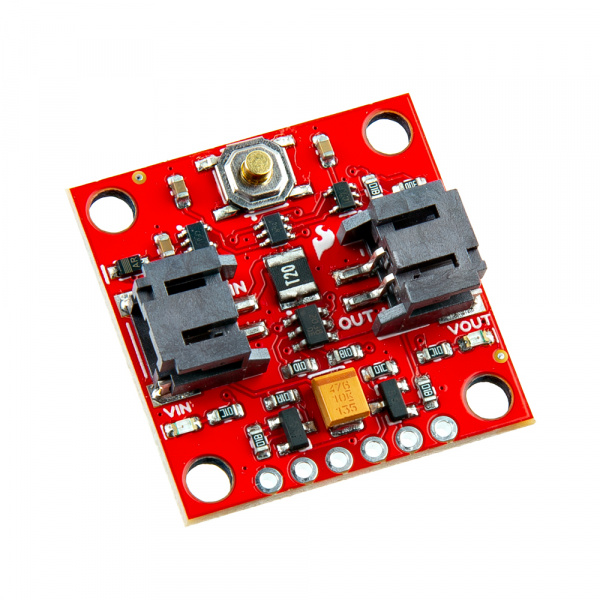
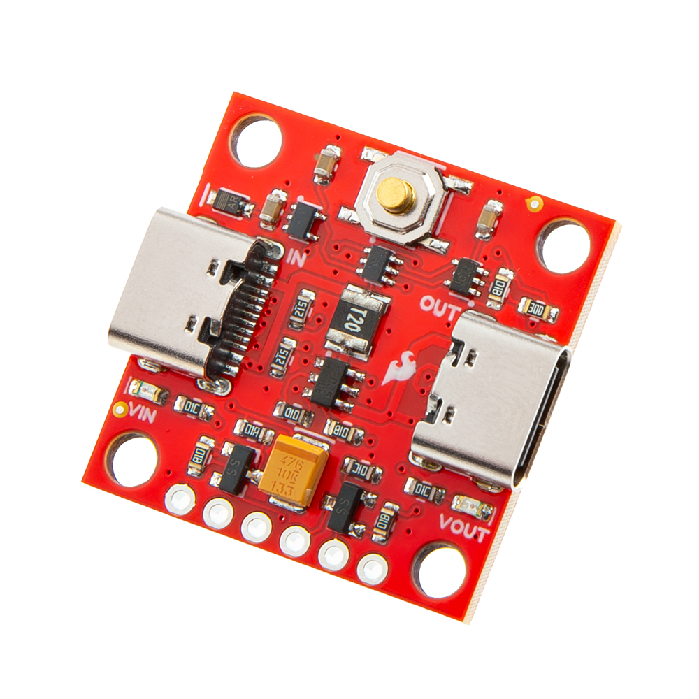
The SparkFun Soft Power Switch is a passive, hard on/off switch with software feedback and control. In other words, it's like the on/off switch on a laptop. A simple press will turn the system on. Another press can (with MCU intervention) turn off the system. And if things go really wrong, pressing and holding the button for ~10 seconds will force a power-down. If you're building something with an enclosed battery and need a good power button, this is the board you need. This version has JST 2mm battery connectors but we also have a version with USB-C connectors.
In this tutorial, we'll go over the hardware and how to hookup the SparkFun Soft Power Switch - JST 2mm to an Arduino. We will also go over an Arduino example to get started.
Required Materials
To follow along with this tutorial, you will need the following materials. You may not need everything though depending on what you have. Add it to your cart, read through the guide, and adjust the cart as necessary.
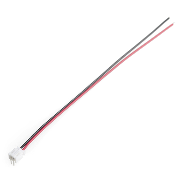
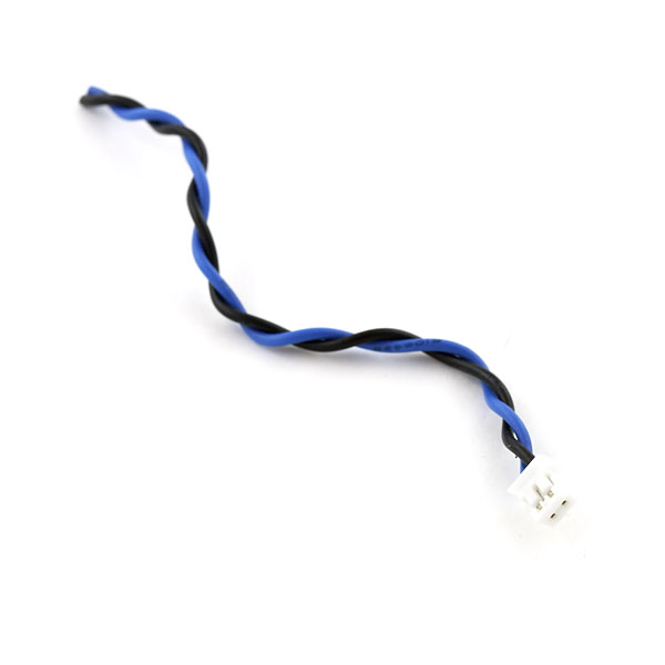
2-Pin JST Cables
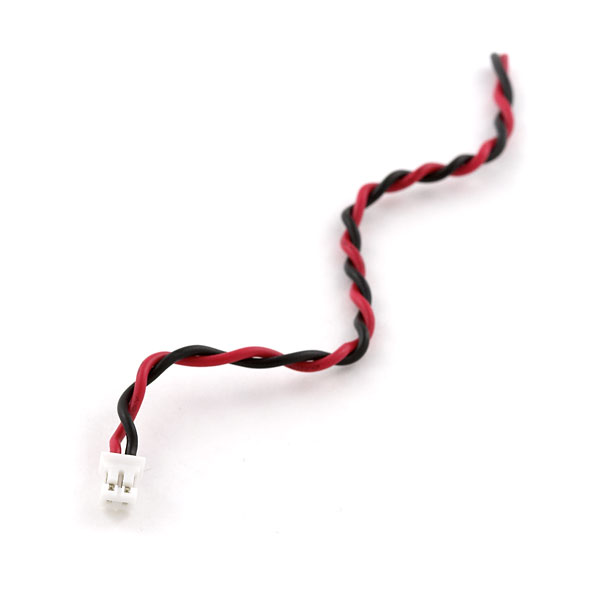
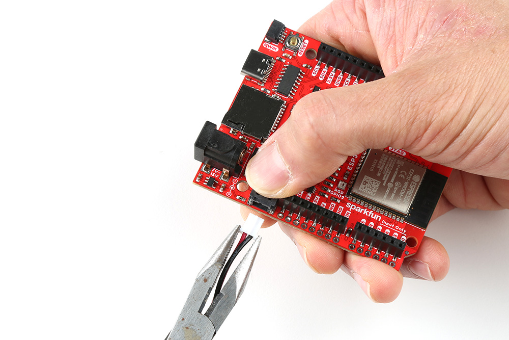
For those that want to take advantage of the 2-pin JST-style connector with 2mm pitch, you can grab the following cables from the catalog. Two jumper 2 wire assemblies were spliced together with heat shrink to easily connect the Soft Power Switch - JST 2mm to the IoT RedBoard's 2-pin JST-style connector.
Tools
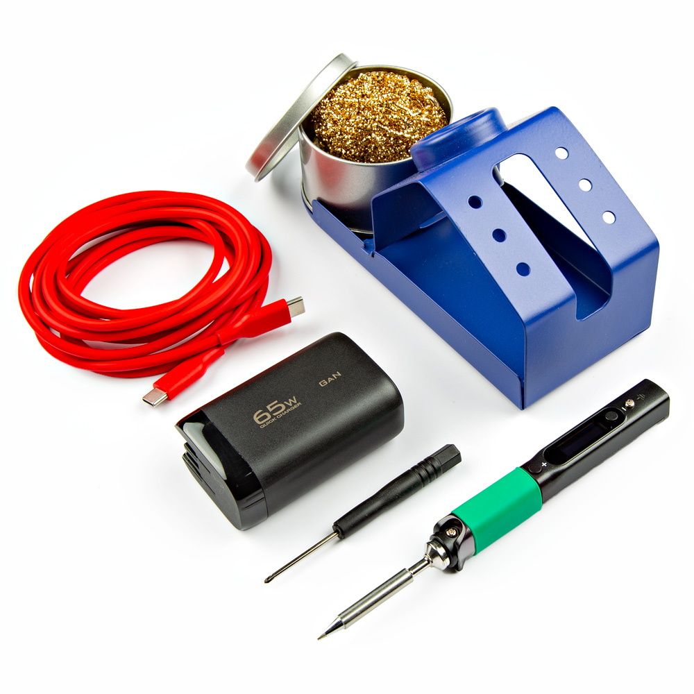
For users connecting to the plated through holes, you will need a soldering iron, solder, and general soldering accessories.
Prototyping Accessories
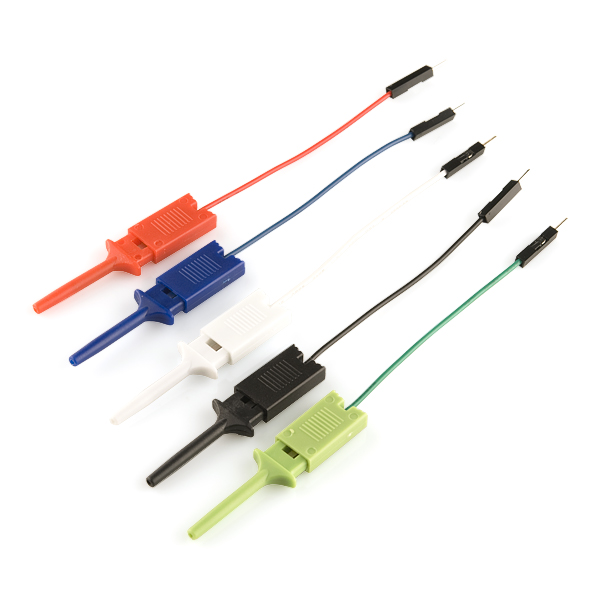
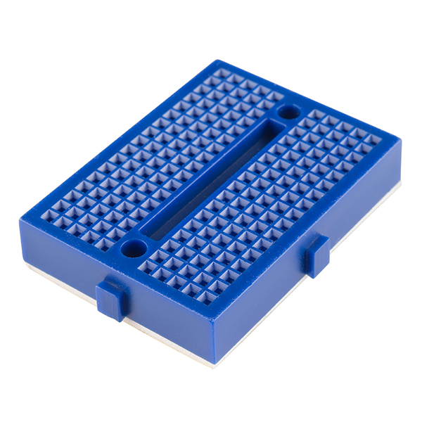
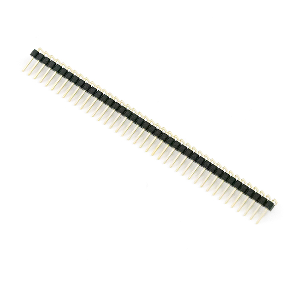
Depending on your setup, you may want to use IC hooks for a temporary connection. However, you will want to solder header pins to connect devices to the plated through holes for a secure connection.
Suggested Reading
If you aren’t familiar with the following concepts, we also recommend checking out a few of these tutorials before continuing.
Hardware Overview
In this section, we will highlight the hardware and pins that are broken out on the SparkFun Soft Power Switch - JST 2mm. For more information, check out our Resources and Going Further on the components used on the breakout board.
Soft Power Switch Versions
The SparkX Mk1 Soft Power Switch is great, but we do see occasional issues caused by component tolerances or the operating temperature. Mk2 is based on an application note by Texas Instruments, and is a completely digital design. It is based around a 74LVC1G175 D-type flip-flop - remember those?! - and is insensitive to temperature and component variation.
It also includes improvements like:
- An over-current self-resetting 2A fuse.
- Input and output LEDs.
- LED jumpers.
- Improved momentary button (i.e. the height of the button is increased).
Differences include:
- The Soft Power Switch - JST 2mm works up to 5.5V only (the Mk1 is good up to 12V).
- For Mk2, driving the fast OFF pin HIGH by the system will force fast power off via software. However for Mk1, the fast OFF pin was driven low.
- Slightly bigger PCB: 1.0"x1.0" sized breakout (the Mk1 was 0.8"x1.0").
Power
Warning
The Soft Power Switch - JST 2mm works up to 5.5V only. (Mk1 is good up to 12V.)
Warning
The Soft Power Switch - JST 2mm was designed to work with DC loads. Unfortunately, the board is not designed for AC loads.
Note
Once the Soft Power Switch - JST 2mm is powered, it will take a few seconds to discharge power after disconnecting the power source from the IN port. So if you decide to do quick power cycle, the board can still be powered if there is not a long enough delay.
The maximum input voltage that the Soft Power Switch - JST 2mm can handle is 5.5V while the minimum input voltage is 1.8V. The board was designed to be used with single cell LiPo batteries with the built-in 2-pin JST connector, so the typical voltage will be about 3.7V nominally. The maximum current draw that the board can handle is 2A continuous and 4A peak (fuse protected). With the VIN LED disabled, the board has a very low quiescent current: <1µA @ 3.75V.
- VIN — This pin is the voltage input. As stated above, the maximum input voltage is 5.5V while the minimum is 1.8V. Voltage is applied to this pin from a single cell LiPo battery which is about 3.7V nominally.
- VOUT — The output voltage of the board whenever the switch is active.
- GND — Of course, is the common, ground voltage (0V reference) for the system.
The Soft Power Switch - JST 2mm also supports battery charging. If the target device has onboard LiPo charging, current can be passed back through the switch circuit and charge the battery.
Power Button and Button State
The board includes a built-in momentary push button as the power button. This pin is broken out to a PTH for users to connect an external button. There is also the PUSH pin to indicate the button's state. The PUSH pin can act as an output to a microcontroller indicating the state of the power button (HIGH = not pressed, LOW = user is pressing power button). This can be used as an input to your firmware to begin to shut down before power is lost. Alternatively, there is also an OFF pin that can be driven HIGH by the system forcing fast power off via software. Below is a summary of the pins broken out.
- BTN — Short for button. If desired, connect this input pin to an external button between BTN and GND.
- PUSH — Open-drain output. This pin requires a pull-up resistor. A low indicates the button is pushed.
- OFF — Drive HIGH to turn the output off.
Note
For Mk2, driving the fast OFF pin HIGH by the system will force fast power off via software. However for Mk1, the fast OFF pin was driven low.
LEDs
- VIN — The VIN LED connects to the input voltage. This indicates when there is voltage at VIN. This LED can be disabled with the LED jumper on the back of the board and below the silkscreen labeled IN.
- VOUT — The VOUT LED connects to the output voltage. This indicates when there is voltage at VOUT. This LED can be disabled with the LED jumper on the back of the board and below the silkscreen labeled OUT.
Jumpers
Note
If this is your first time working with jumpers, check out the How to Work with Jumper Pads and PCB Traces tutorial for more information.
The back of the board includes jumpers to configure the board.
- LED (below IN) — By default, the LED jumper located below the silkscreen labeled IN is closed. This connects the VIN LED to the input voltage. Cutting this will disable the LED for the input voltage.
- LED (below OUT) — By default, the LED jumper located below the silkscreen labeled OUT is closed. This connects the LED to the output voltage. Cutting this jumper will disable the LED for the output voltage.
3D Model
A 3D model of the board and components was exported to a STEP file using KiCad.
Board Dimensions
The board is 1.0" x 1.0" (2.54mm x 2.54mm). There are 4x mounting holes by the corners of the board. You can use 4-40 standoffs to mount the board to a panel or enclosure.
Hardware Hookup
In this section, we will go over how to connect to the Soft Power Switch - JST 2mm.
Connecting via PTH
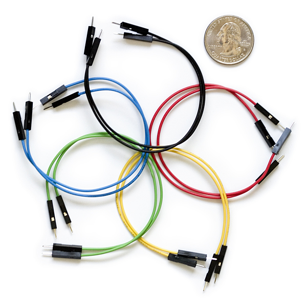
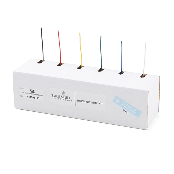
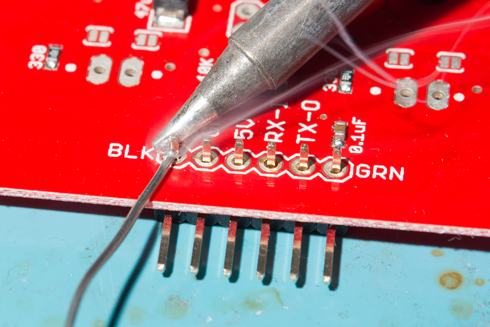
For temporary connections to the PTHs, you could use IC hooks to test out the pins. However, you'll need to solder headers or wires of your choice to the board for a secure connection. You can choose between a combination of header pins and jumper wires, or stripping wire and soldering the wire directly to the board.
Input Power
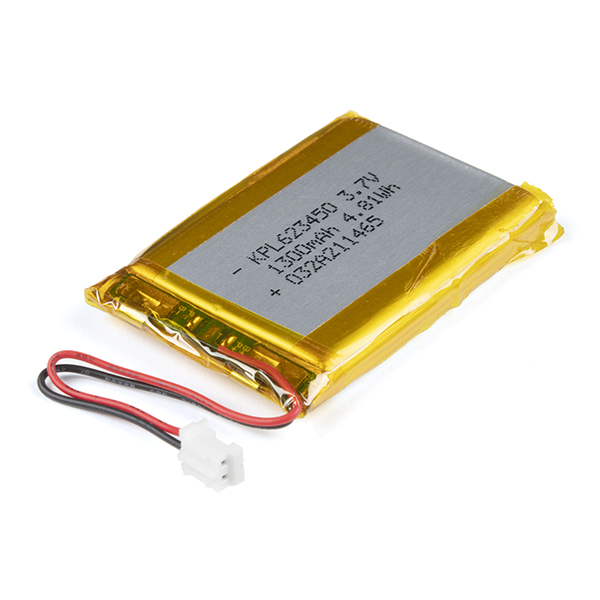
The board was designed to be used with single cell LiPo batteries with the built-in 2-pin JST connector. Simply insert the LiPo Battery into the JST connector labeled as IN.
Of course, power can also be soldered directly to the PTH as well.
| Power Supply | Soft Power Switch - JST 2mm |
|---|---|
| 1.8V to 5.5V Typically 3.7V if using a LiPo Battery (Red Wire) |
VIN |
| GND (Black Wire) | GND |
Remember, the Soft Power Switch - JST 2mm also supports battery charging. If the target device has onboard LiPo charging, current can be passed back through the switch circuit and charge the battery. For more information about LiPo battery charging and care, make sure to check the tutorial on Single Cell LiPo Battery Care.
Output Power
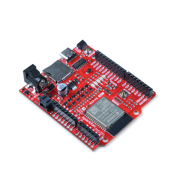
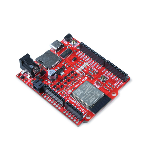
For boards that have a built-in 2-pin JST connector for LiPo batteries, you can splice two JST cables together. Then you can insert it between the Soft Power Switch's JST connector labeled OUT and the other end will be inserted into the JST connector of the target board being powered (in this case, the SparkFun IoT RedBoard - ESP32 Development Board).
Of course, power can also be soldered directly to the PTH as well. Since we are powering the output with a single cell LiPo battery, you will need to connect it to your system's battery input. In this case, VBATT net was labeled as + on the board. Depending on your system, it may be labeled as VBAT, RAW, or VCC. Make sure to check the board's hardware design before deciding to connect VOUT to your system.
| Soft Power Switch - JST 2mm | SparkFun IoT RedBoard - ESP32 Development Board |
|---|---|
| VOUT | + |
| GND | - |
Note
The voltage range of the Soft Power Switch - JST 2mm is between 1.8V to 5.5V. Users can also connect a different power source and connect the output to VIN or 5V of their system. Just make that the voltage is within the operating range of the target device.
External Button
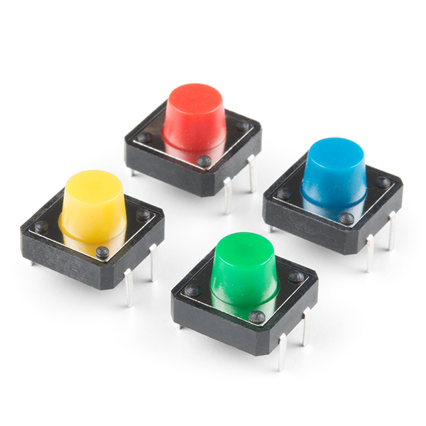
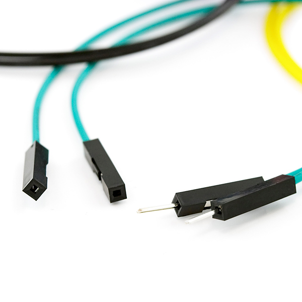
For users that need to connect an external button, you will simply need to connect one terminal of the button to BTN and the other terminal to GND. In this case, IC hooks and F/M jumper wires were used to connect an external momentary push button.
| Soft Power Switch - JST 2mm | Button |
|---|---|
| BTN | Normally Open Pin |
| GND | Common Pin |
Off and Push
To connect to the OFF and PUSH pins with a microcontroller, you will need two GPIO pins with code to control or read the Soft Power Switch Mk2. Depending on your microcontroller, you may need to adjust the pin connections and definitions with respect to the microcontroller's GPIO pins.
| Soft Power Switch - JST 2mm | SparkFun IoT RedBoard - ESP32 Development Board |
|---|---|
| OFF | 32 (or A4)
|
| PUSH | 14
|
Tip
Remember, the PUSH pin requires a pull-up resistor when connecting it to a microcontroller's GPIO pin. You can use the internal pull-up resistor on the microcontroller so that the pin is not floating.
Arduino Serial Output
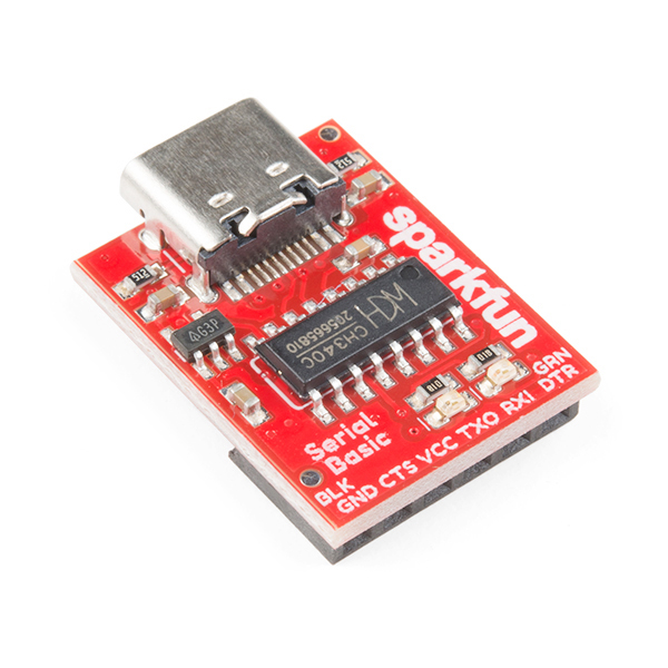
To view the Arduino's serial output when powering the system with a LiPo battery, you will need to wire a 3.3V Serial Basic Breakout to the Arduino's serial UART. In this case, we connected to the SparkFun IoT RedBoard - ESP32 Development Board primary UART port. Depending on your microcontroller, you may need to adjust the pin connections and definitions with respect to the microcontroller's UART pins.
| 3.3V Serial Basic | SparkFun IoT RedBoard - ESP32 Development Board |
|---|---|
| TXO | 3/RX-0 |
| RXI | 1/TX-0 |
| GND | GND |
Arduino Example
Arduino
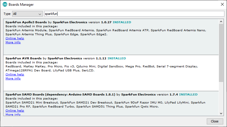
This example assumes you are using the latest version of the Arduino IDE on your desktop. If this is your first time using Arduino IDE, library, or board add-on, please review the following tutorials.
Note
If you've never connected an CH340 device to your computer before, you may need to install drivers for the USB-to-serial converter. Check out our section on "How to Install CH340 Drivers" for help with the installation.
For the scope of this tutorial, we will highlight the example from the GitHub repository to get started. Head to the GitHub repository to download the example.
Upload Arduino Example
After unzipping the compressed files, navigate to the example: ... > SparkFun_Soft_Power_Switch_USB-C-main > Examples > SoftPowerSwitchMk2_Example > SoftPowerSwitchMk2_Example.
If you have not already, connect the Soft Power Switch's power, OFF, and PUSH to your Arduino's GPIO pins. In this case, we used the SparkFun IoT RedBoard - ESP32 Development Board. Depending on your microcontroller, you may need to adjust the pin connections and definitions with respect to the microcontroller's GPIO pins. At this point, you can connect the LiPo battery into the Soft Power Switch's IN port and connect the OUT port to the RedBoard's battery input.
| Soft Power Switch - JST 2mm | SparkFun IoT RedBoard - ESP32 Development Board |
|---|---|
| VOUT | + |
| GND | GND |
| OFF | 32 (or A4)
|
| PUSH | 14
|
For users using an Arduino microcontroller, select your board in the Tools menu (in our case the SparkFun ESP32 RedBoard IoT RedBoard) and the correct Port it enumerated on. You can also copy or paste the code as shown below. Then click "Upload".
    /*
      Control the power to a system using the SparkFun Soft Power Switch Mk2
      By: Nathan Seidle
      Adapted by: Paul Clark
      SparkFun Electronics
      Date: March 14th, 2024
      License: MIT. See license file for more information

      This example assumes the OFF pin is connected.

      A simple tap of the power button will turn on the system. If the power button is not being pressed
      (accidental tap) the system will turn off after ~20ms. If the system turns on and sees the power
      button held for 0.5s, it will begin normal operation.

      During normal system operation, if user presses the power button for 2s, the system
      will shut down. This means the power button can also be used as a general 'select' button as
      long as user doesn't hold button for more than 2s.

      This example will output serial states. If you are powering your board over a USB connection then
      the power button can't do its job. We did our testing by connecting the TX and GND pins of a RedBoard to
      an external USB to Serial adapter. That way the battery + Soft Power Switch could control power
      to the board.
    */

    //Hardware connections - GPIO pins (change these as required)
    int _PUSH = 14; // Connect this GPIO to the PUSH breakout pad
    int _OFF = 32; // Connect this GPIO to the OFF breakout pad

    int STAT_LED = LED_BUILTIN;

    unsigned long powerPressedStartTime = 0;

    int debounceDelay = 20;

    //Uncomment the following line to turn on shutdown time measurements
    //#define PRINT_TIMER_OUTPUT

    void setup()
    {
      Serial.begin(115200);
      Serial.println("Soft Power Switch Mk2 example");

      pinMode(_PUSH, INPUT_PULLUP);

      //User has pressed the power button to turn on the system
      //Was it an accidental bump or do they really want to turn on?
      //Let's make sure they continue to press for two seconds
      Serial.print("Initial power on check");
      powerPressedStartTime = millis();
      while (digitalRead(_PUSH) == LOW)
      {
        //Wait for user to stop pressing button.
        //What if user has left something heavy pressing the power button?
        //The soft power switch will automatically turn off the system! Handy.
        delay(100);

        if ((millis() - powerPressedStartTime) > 500)
          break;
        Serial.print(".");
      }
      Serial.println();

      if ((millis() - powerPressedStartTime) < 500)
      {
        Serial.println("Power button tap. Returning to off state. Powering down");
        powerDown();
      }

      Serial.println("User wants to turn system on!");
      powerPressedStartTime = 0; //Reset var to return to normal 'on' state

      //Here we display something to user indicating system is on and running
      //For example an external display or LED turns on
      pinMode(STAT_LED, OUTPUT);
      digitalWrite(STAT_LED, HIGH);

      Serial.println("Press 'r' to enter infinite loop to test power-down override");
      Serial.println("Press 'z' to do a powerdown");
      Serial.println("Press and hold power button for 2s to do a powerdown");

      while (Serial.available()) // Flush the Serial RX buffer
        Serial.read();
    }

    void loop()
    {
      if (Serial.available())
      {
        char incoming = Serial.read();

        if (incoming == 'z')
        {
          Serial.println("Power down");
          powerDown();
        }
        else if (incoming == 'r')
        {
          Serial.println("System locked. Now hold power button to force power down without using software");

          //Here we wait for user press button so we can time it
          while (digitalRead(_PUSH) == HIGH)
            delay(1);

          powerPressedStartTime = millis();
          Serial.println("Doing nothing, waiting for power override to kick in");
          while (1)
          {
    #ifdef PRINT_TIMER_OUTPUT
            Serial.println(millis() - powerPressedStartTime);
    #endif
            delay(1);

            if(digitalRead(_PUSH) == HIGH) break;
          }
          Serial.println("User released button before forced powered could complete. Try again, but hold power button for 7s");
          powerPressedStartTime = 0; //Reset var to return to normal 'on' state
        }
      }

      if (digitalRead(_PUSH) == LOW && powerPressedStartTime == 0)
      {
        //Debounce check
        delay(debounceDelay);
        if (digitalRead(_PUSH) == LOW)
        {
          Serial.println("User is pressing power button. Start timer.");
          powerPressedStartTime = millis();
        }
      }
      else if (digitalRead(_PUSH) == LOW && powerPressedStartTime > 0)
      {
        //Debounce check
        delay(debounceDelay);
        if (digitalRead(_PUSH) == LOW)
        {
          if ((millis() - powerPressedStartTime) > 2000) // Check if button has been held for >= 2 seconds
          {
            Serial.println("Time to power down!");
            powerDown();
          }
        }
      }
      else if (digitalRead(_PUSH) == HIGH && powerPressedStartTime > 0)
      {
        //Debounce check
        delay(debounceDelay);
        if (digitalRead(_PUSH) == HIGH)
        {
          Serial.print("Power button released after ms: ");
          Serial.println(millis() - powerPressedStartTime);
        }
        powerPressedStartTime = 0; //Reset var to return to normal 'on' state
      }
    }

    //Immediately power down
    void powerDown()
    {
      //Indicate to user we are shutting down
      digitalWrite(STAT_LED, LOW);

      Serial.println("Pulling OFF high");
      Serial.flush();

      powerPressedStartTime = millis();

      pinMode(_OFF, OUTPUT);
      digitalWrite(_OFF, HIGH); // Pull OFF high to turn the power off

      while (1)
      {
    #ifdef PRINT_TIMER_OUTPUT
        Serial.println(millis() - powerPressedStartTime);
    #endif
        delay(1);
      }
    }
After uploading the code, disconnect the Arduino from your COM port. Then wire a 3.3V Serial Basic Breakout to the Arduino's serial UART. In this case, we connected to the SparkFun IoT RedBoard - ESP32 Development Board. Depending on your microcontroller, you may need to adjust the pin connections and definitions with respect to the microcontroller's UART pins.
| 3.3V Serial Basic | SparkFun IoT RedBoard - ESP32 Development Board |
|---|---|
| TXO | 3/RX-0 |
| RXI | 1/TX-0 |
| GND | GND |
Initial Boot
Open the Serial Monitor or terminal emulator of your choice, and connect to the 3.3V Serial Basic Breakout's COM port with the baud rate set to 115200. Hit the reset button on the ESP32 IoT RedBoard. Since we are using the ESP32, we will see an initial output when the microcontroller boots up. If the button is not held down for 0.5 seconds, you will receive the following message as shown below.
Soft Power Switch Mk2 example
Initial power on check
Power button tap. Returning to off state. Powering down
Pulling OFF high
Normal Operation - Power On
Press down on the button for just over 0.5 seconds (but no longer than 2 seconds) to power your Arduino for normal system operation. Once the ESP32 boots up, you should see the following output. A timer will begin checking the length of time that the button has been pressed down. Once the button has been released, you will receive an output indicating the amount of time that the button has been pressed down after 0.5 seconds.
Soft Power Switch Mk2 example
Initial power on check....
User wants to turn system on!
Press 'r' to enter infinite loop to test power-down override
Press 'z' to do a powerdown
Press and hold power button for 2s to do a powerdown
User is pressing power button. Start timer.
Power button released after ms: 300
Note
The wake-up time can be tweaked to your own user experience. We found 500ms for power up work really well.
Normal Operation - Power Off
Let's try turning the power off under normal operation. Press the power button for 2 seconds to power down the Arduino. You will receive the following output. You will also notice that the power LEDs on the SparkFun IoT RedBoard - ESP32 turn off indicating that there is no power.
Note
The power-down time can be tweaked to your own user experience. We found 2s for power-down work really well. If you decide to adjust the power-down time, make sure to not exceed ~10 seconds as the force power down will take into effect.
System Lock and Power Down via Arduino Serial Monitor
Remember the output from earlier? There were additional options to control the Soft Power Switch from the Arduino Serial Monitor. Press down on the power button for 0.5 seconds to enter the normal operation again. You will be presented with two options:
- r — Sending an r will cause the Arduino to enter an infinite loop to test power-down override. This will lock the system and force the Soft Power Switch to only shutdown when the button is pressed down rather then sending a character to the Arduino to power down. When locking the system, you will need to press the button down for 7 seconds to force the Soft Power Switch to power down. Once the button has been pressed down for 7 seconds, the Soft Power Switch will shut power off at the OUT port.
- z — Sending a z will power down the Arduino.
Let's send an r to lock the system to force the Soft Power Switch to power down. Then press down on the power button for 7 seconds. You will receive the following message indicating that the system is locked. Once the power button is pressed down, an additional message on the next line will be output to indicate that we are waiting for the power override. After 7 seconds, power will be disabled at the OUT port and the IoT RedBoard - ESP32 will turn off.
System locked. Now hold power button to force power down without using software
Doing nothing, waiting for power override to kick in
Note
If the button is released before 7 seconds, you will receive the following message indicating that the forced power down could not be completed when the system is locked. This will break out of the infinite loop and require you to send another r through the serial terminal in order to test the power-down override again.
Troubleshooting
General Troubleshooting Help
Note
Not working as expected and need help?
If you need technical assistance and more information on a product that is not working as you expected, we recommend heading on over to the SparkFun Technical Assistance page for some initial troubleshooting.
If you don't find what you need there, the SparkFun Forums are a great place to find and ask for help. If this is your first visit, you'll need to create a forum account to search product forums and post questions.
Resources
Now that you've successfully got your SparkFun Soft Power Switch Mk2 - JST 2mm up and running, it's time to incorporate it into your own project! For more information, check out the resources below:
- Schematic (PDF)
- KiCad Files (ZIP)
- 3D Model (STEP)
- Board Dimensions (JPG)
- Component Datasheets
- GitHub Hardware Repo
Or check out the other Soft Power Switch with USB connectors!
