Introduction
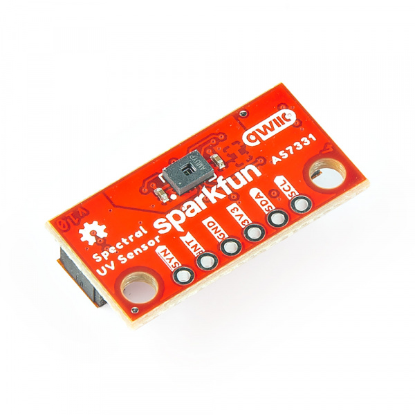
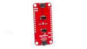
The SparkFun Spectral UV Sensor - AS7331 (Qwiic) and Mini Spectral UV Sensor - AS7331 (Qwiic) feature the AS7331 UV sensor from ams OSRAM© which measures UV radiation on three channels: UVA (320-400nm), UVB (280-320nm), and UVC (200-280nm). Each channel on the AS7331 has an individual photodiode with built-in interference filters to ensure high sensitivity and accuracy across all three channels. The AS7331 communicates over I2C so naturally we put it on Standard (1"x1") and Mini (1"x0.5") Qwiic breakouts to integrate into our Qwiic Connect System.

This guide goes over the AS7331 UV sensor and other hardware on these Qwiic breakouts, how to assemble them into a circuit and how to use them with the SparkFun AS7331 Arduino library.
Required Materials
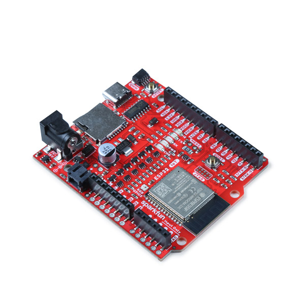
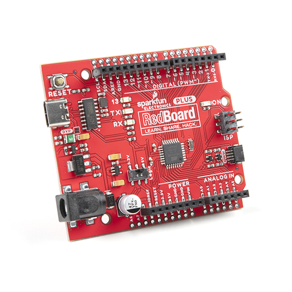
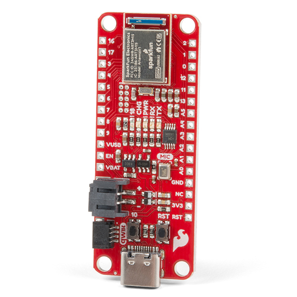
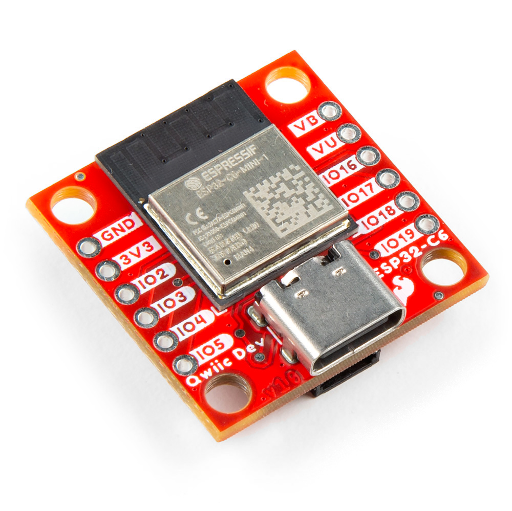
In order to follow along with this guide, you'll need the following materials. You'll need a microcontroller to connect the breakouts to. The development boards listed below come with Qwiic connectors for easy connection using the Qwiic system:
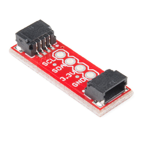
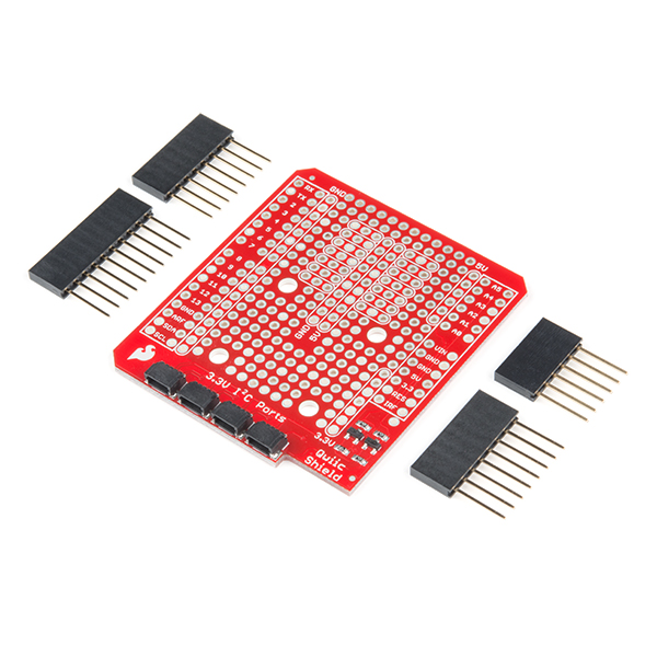
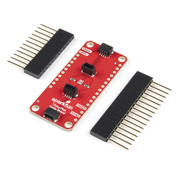
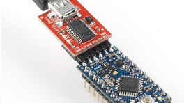
If your chosen microcontroller is not already Qwiic-enabled, you can add that functionality with one or more of the following items:
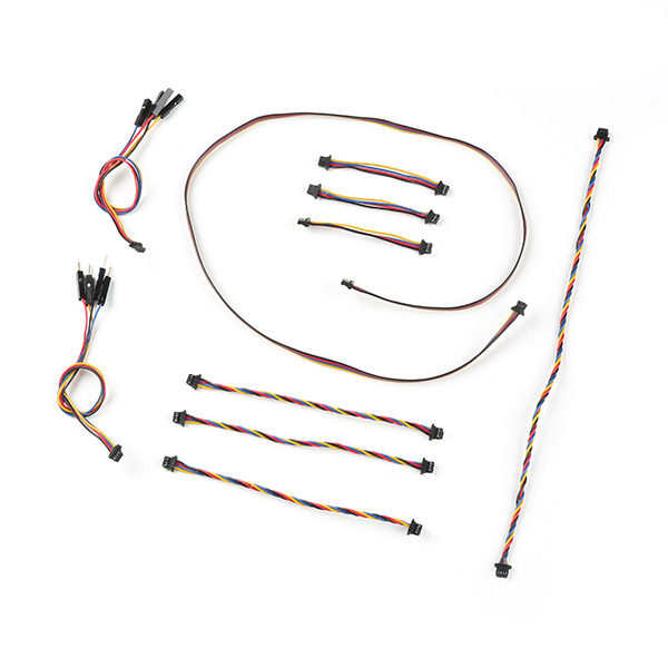
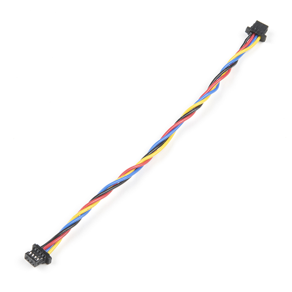
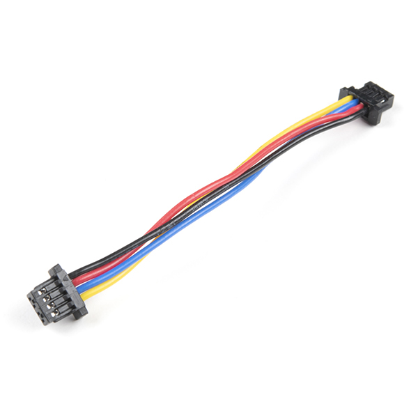
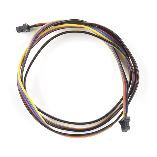
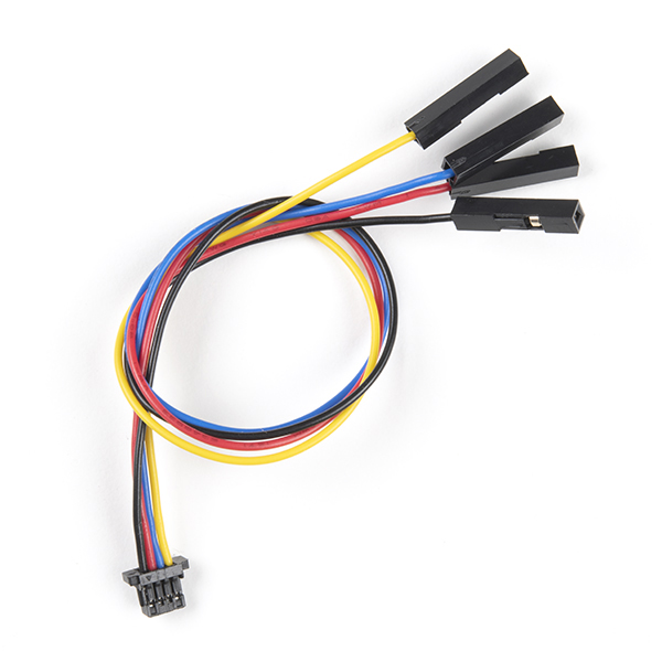
You will also need at least one Qwiic cable to connect your breakout to your microcontroller:
Optional Materials
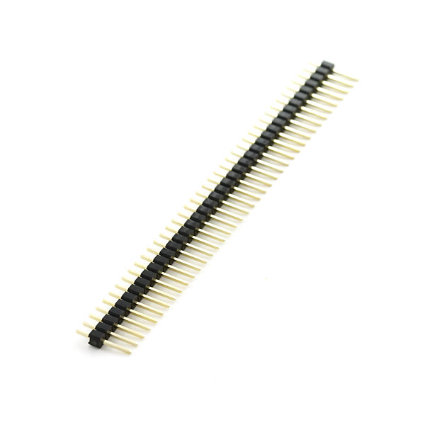
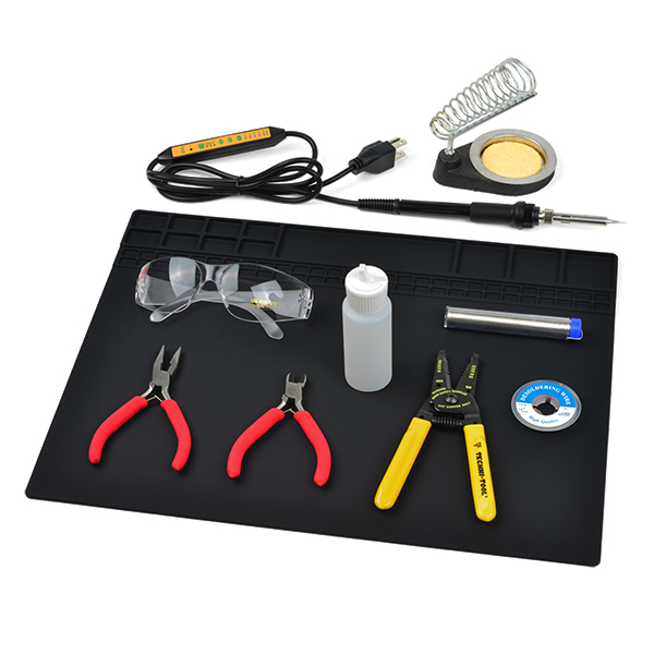
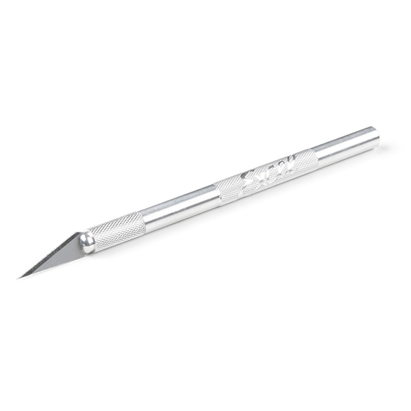
If you prefer a soldered connection or want to modify the solder jumpers on these Qwiic breakouts you you may need some of the products listed below:
Suggested Reading
We designed this board for integration into SparkFun's Qwiic connect system. Click on the banner below to learn more about the SparkFun Qwiic Connect System.

Before getting started with this Hookup Guide, you may want to read through the tutorials below if you are not familiar with the concepts covered in them or want a refresher. If you are using either of the Qwiic Shields linked above, we recommend reading through their respective Hookup Guides before continuing with this tutorial:


Hardware Overview
AS7331 Spectral UV Sensor
The AS7331 spectral UV sensor from ams measures UV radiation over three channels (UVA, UVB, and UVC). Each channel is isolated from the other and has its own photodiode with a built-in filter to help with accuracy and interference from other channels.


The AS7331 has extensive configuration options to customize the sensor's responsiveness, sensitivity, clock speed, and conversion time, among other settings. These configuration options allow users to optimize the sensor for their application. For example, a high gain setting results in a more sensitive response from the sensor but a lower maximum detectable irradiance (in µW/cm2) whereas a low gain has much less sensitivity but a much higher maximum detectable irradiance. For detailed information on the conversion equations and how all the available settings affect performance, refer to section 7.4 of the datasheet Note, these configurations apply across all three channels. It has four operating modes: Command (CMD), Continuous (CONT), Synchronized Start (SYNS), and Synchronized Start/End (SYND). The list below outlines the operating modes' behaviors:
- CMD Mode - "One-shot" mode. Takes a single measurement and conversion controlled by the I2C interface.
- CONT Mode - Continous mode. Takes continuous measurements and conversions on set intervals.
- SYNS Mode - Synchronized start mode. A connected microcontroller starts measurements through an I/O pin connected to the SYN pin.
- SYND Mode - Synchronized start and stop mode. A connected microcontroller starts and stops measurements through an I/O pin connected to the SYN pin.
The sensor operates over I2C with a pin-configured I2C address supporting four separate addresses (the breakout board sets this to 0x74 by default). Refer to the datasheet for a complete overview of the AS7331.
Qwiic and PTH Pins
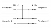
Both boards include a pair of Qwiic connectors for the I2C interface (SDA, SCL, 3.3V, and Ground) as well as a 0.1"-spaced plated through hole (PTH) header that includes power supply pins (3.3V and Ground) the I2C interface as well as the AS7331's SYNC and READY/INT pins.

Power
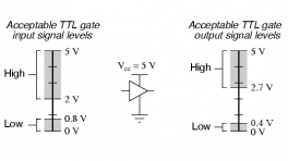
The AS7331 accepts a supply voltage between 2.7V and 3.6V. Power to these boards can be supplied either over one of the Qwiic connectors or through the 3.3V and GND PTH pins.
LEDs
These breakouts only have a red Power LED to indicate whenever the board is powered.


Jumpers
Never modified a jumper before?
Check out our Jumper Pads and PCB Traces tutorial for a quick introduction!
The boards have three solder jumpers labeled PWR, A0, and A1. The PWR jumper completes the power LED circuit. Open it to disable the Power LED to help reduce the current consumption. The A0 and A1 solder jumpers control the AS7331's I2C address. They default to tie both address pins to Ground to set the I2C address to 0x74. The table below outlines the jumper positions for the four available I2C addresses:


| A1 | A0 | Address |
|---|---|---|
| GND | GND | 0x74 (default) |
| GND | VDD | 0x75 |
| VDD | GND | 0x76 |
| VDD | VDD | 0x77 |
Board Dimensions
The Standard version of the Spectral UV Sensor measures 1.00" x 1.00" (25.4mm x 25.4mm) and the Mini version measures 1.00" x 0.50" (25.4mm x 12.7mm). The Standard has four mounting holes and the Mini has two mounting holes. All of these fit a 4-40 screw.


Need more measurements?
For more information about the board's dimensions, users can download the Eagle files(Standard & Mini) for the board. These files can be opened in Eagle and additional measurements can be made with the dimensions tool.
Eagle - Free Download!
Eagle is a CAD program for electronics that is free to use for hobbyists and students. However, it does require an account registration to utilize the software.
 Dimensions Tool
This video from Autodesk demonstrates how to utilize the dimensions tool in Eagle, to include additional measurements:
Hardware Assembly
Qwiic Assembly
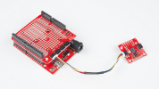
Assembling these breakouts into a Qwiic circuit is as simple as plugging the board into your chosen microcontroller with a Qwiic cable. After assembling your circuit, it should look similar to the photos below:


Soldered Assembly
Users who prefer a soldered connection or wish to use the SYNC and READY/INT pins should solder to the board for permanent connections.
New to soldering?
If you have never soldered before or need a quick refresher, check out our How to Solder: Through-Hole Soldering guide.

Arduino Library
Software Setup
Arduino IDE
Most users may already be familiar with the Arduino IDE and its use. However, for those of you who have never heard the name Arduino before, feel free to check out the Arduino website. To get started with using the Arduino IDE, check out our tutorials below:
-
Installing the Arduino IDE
-
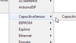
Installing an Arduino Library
-
Installing Board Definitions in the Arduino IDE
SparkFun AS7331 Arduino Library
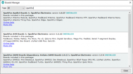
We've written an Arduino library for users to quickly get started with and customize the Spectral UV Sensor Breakouts. Install the library through the Arduino Library Manager tool by searching for "SparkFun AS7331". If you prefer to manually install the library, download a .ZIP of it from the GitHub Repository by clicking the button below:
Arduino Examples
icon: simple/arduino
Now that we have the AS7331 Arduino library installed, let's take a closer look at a couple of the examples included in it.
Example 1 - Basic One-Shot
The first example demonstrates the basics of configuring the AS7331, initializing it on the I2C bus to operate in command (one-shot) mode and printing out measured data over serial. This helps conserve power as the sensor powers on for a single measurement and conversion and then powers back down to sleep mode. Open the example in Arduino by navigating to File > Examples > SparkFun AS7331 Arduino Library > Example01_Basic_OneShot or you can copy the code below into a blank sketch. Select your Board and Port and click the "Upload" button.
Example 1 - Basic One Shot
 /*
   Using the AMS AS7331 Spectral UV Sensor in Command/One Shot (CMD) Mode.

   This example shows how operate the AS7331 in the default CMD mode. The start
   command is sent, then delays until the conversion time has passed before
   reading out the UV values.

   By: Alex Brudner
   SparkFun Electronics
   Date: 2023/11/17
   SparkFun code, firmware, and software is released under the MIT License.
     Please see LICENSE.md for further details.

   Hardware Connections:
   IoT RedBoard --> AS7331
   QWIIC --> QWIIC

   Serial.print it out at 115200 baud to serial monitor.

   Feel like supporting our work? Buy a board from SparkFun!
   https://www.sparkfun.com/products/23517 - Qwiic 1x1
   https://www.sparkfun.com/products/23518 - Qwiic Mini
 */

 #include <Arduino.h>
 #include <SparkFun_AS7331.h>
 #include <Wire.h>

 SfeAS7331ArdI2C myUVSensor;

 void setup()
 {
     Serial.begin(115200);
     while (!Serial)
     {
         delay(100);
     };
     Serial.println("AS7331 UV A/B/C Command (One-shot) mode Example.");

     Wire.begin();

     // Initialize sensor and run default setup.
     if (myUVSensor.begin() == false)
     {
         Serial.println("Sensor failed to begin. Please check your wiring!");
         Serial.println("Halting...");
         while (1)
             ;
     }

     Serial.println("Sensor began.");

     // Set measurement mode and change device operating mode to measure.
     if (myUVSensor.prepareMeasurement(MEAS_MODE_CMD) == false)
     {
         Serial.println("Sensor did not get set properly.");
         Serial.println("Halting...");
         while (1)
             ;
     }

     Serial.println("Set mode to command.");
 }

 void loop()
 {

     // Send a start measurement command.
     if (ksfTkErrOk != myUVSensor.setStartState(true))
         Serial.println("Error starting reading!");

     // Wait for a bit longer than the conversion time.
     delay(2 + myUVSensor.getConversionTimeMillis());

     // Read UV values.
     if (ksfTkErrOk != myUVSensor.readAllUV())
         Serial.println("Error reading UV.");

     Serial.print("UVA:");
     Serial.print(myUVSensor.getUVA());
     Serial.print(" UVB:");
     Serial.print(myUVSensor.getUVB());
     Serial.print(" UVC:");
     Serial.println(myUVSensor.getUVC());

     delay(2000);
 }
Once the code finishes uploading, open the serial monitor with the baud set to 115200 and you should see the initialization success messages and then UV data begin to print out every 2 seconds like the screenshot below shows:

Code to Note
The myUVSensor.begin function sets the AS7331 to operate in Command Mode (One Shot) by default. Switching to other modes requires calling the myUVSensor.startMeasurement(MEAS_MODE_CONT). The other examples in the library demonstrate how to switch to the other three operating modes.
Example 2 - Continuous Mode
Example 2 demonstrates how to change from the default settings to have the AS7331 operate in Continuous Mode. This example requires some additional assembly to connect the INT pin to an interrupt-capable pin on your microcontroller. The example defaults to use D26 so adjust this line if you change which pin is used for the interrupt:
Open the example in Arduino by navigating to File > Examples > SparkFun AS7331 Arduino Library > Example01_Basic_OneShot or you can copy the code below into a blank sketch. Select your Board and Port and click the "Upload" button.
Example 2 - CONT Mode
 /*
   Using the AMS AS7331 Spectral UV Sensor in Continuous (CONT) Mode.

   This example shows how operate the AS7331 in CONT mode. The break time
   register sets the delay between measurements so that the processor can read
   out the results without interfering with the ADC.

   By: Alex Brudner
   SparkFun Electronics
   Date: 2023/11/27
   SparkFun code, firmware, and software is released under the MIT License.
     Please see LICENSE.md for further details.

   Hardware Connections:
   IoT RedBoard --> AS7331
   QWIIC --> QWIIC
   26  --> INT

   Serial.print it out at 115200 baud to serial monitor.

   Feel like supporting our work? Buy a board from SparkFun!
   https://www.sparkfun.com/products/23517 - Qwiic 1x1
   https://www.sparkfun.com/products/23518 - Qwiic Mini
 */

 #include <Arduino.h>
 #include <SparkFun_AS7331.h>
 #include <Wire.h>

 SfeAS7331ArdI2C myUVSensor;

 const uint8_t interruptPin = 26;
 volatile bool newDataReady = false;

 void setup()
 {
     Serial.begin(115200);
     while (!Serial)
     {
         delay(100);
     };
     Serial.println("AS7331 UV A/B/C Continuous mode example.");

     Wire.begin();

     // Configure Interrupt.
     pinMode(interruptPin, INPUT);
     attachInterrupt(digitalPinToInterrupt(interruptPin), dataReadyInterrupt, RISING);

     // Initialize sensor and run default setup.
     if (myUVSensor.begin() == false)
     {
         Serial.println("Sensor failed to begin. Please check your wiring!");
         Serial.println("Halting...");
         while (1)
             ;
     }

     Serial.println("Sensor began.");

     // Set the delay between measurements so that the processor can read out the
     // results without interfering with the ADC.
     // Set break time to 900us (112 * 8us) to account for the time it takes to poll data.
     if (ksfTkErrOk != myUVSensor.setBreakTime(112))
     {
         Serial.println("Sensor did not set break time properly.");
         Serial.println("Halting...");
         while (1)
             ;
     }

     // Set measurement mode and change device operating mode to measure.
     if (myUVSensor.prepareMeasurement(MEAS_MODE_CONT) == false)
     {
         Serial.println("Sensor did not get set properly.");
         Serial.println("Spinning...");
         while (1)
             ;
     }

     Serial.println("Set mode to continuous. Starting measurement...");

     // Begin measurement.
     if (ksfTkErrOk != myUVSensor.setStartState(true))
         Serial.println("Error starting reading!");
 }

 void loop()
 {

     // If an interrupt has been generated...
     if (newDataReady)
     {
         newDataReady = false;

         if (ksfTkErrOk != myUVSensor.readAllUV())
             Serial.println("Error reading UV.");

         Serial.print("UVA:");
         Serial.print(myUVSensor.getUVA());
         Serial.print(" UVB:");
         Serial.print(myUVSensor.getUVB());
         Serial.print(" UVC:");
         Serial.println(myUVSensor.getUVC());
     }
 }

 void dataReadyInterrupt()
 {
     newDataReady = true;
 }
After uploading, open the serial monitor with the baud set to 115200 and you should see the initialization messages print out followed by a continuous flow of UV data.
Code to Note
As mentioned above, the myUVSensor.begin function sets the AS7331 to operate in Command Mode so after initializing the sensor the code sets the AS7331 to operate in Continuous Mode:
// Set measurement mode and change device operating mode to measure.
  if(myUVSensor.startMeasurement(MEAS_MODE_CONT) == false) {
    Serial.println("Sensor did not get set properly.");
    Serial.println("Spinning...");
    while(1);
Troubleshooting Tips
Resources:
For more information about the Spectral UV Sensor - Qwiic, check out the following resources listed below:
- Schematic:
- Eagle Files:
- Board Dimensions:
- Datasheet (AS7311)
- SparkFun AS7331 Arduino Library
- Hardware GitHub Respository