Introduction
-
SparkFun Thing Plus - ESP32-S3
SKU: DEV-24408
-
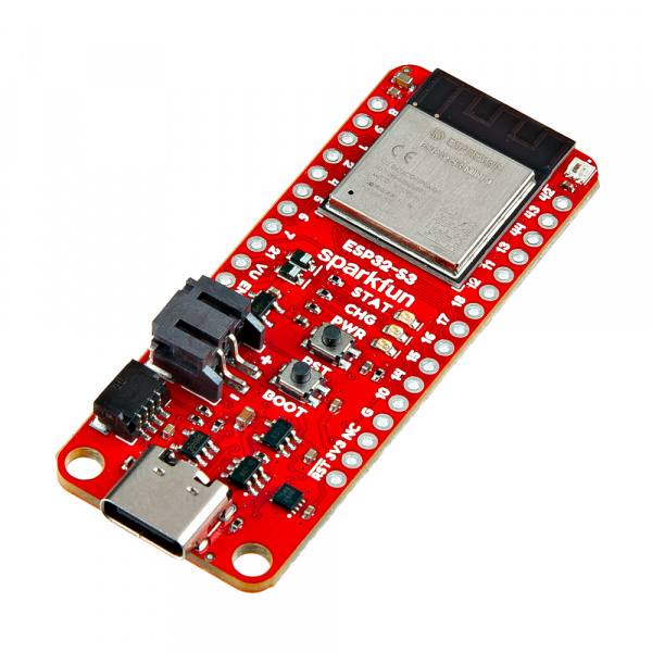
The SparkFun Thing Plus - ESP32-S3 features the powerful and versatile ESP32-S3 from espressif™. The ESP32-S3 It includes a LiPo battery charger and fuel gauge, µSD card slot, an addressable LED and more. The Thing Plus footprint breaks out all of the ESP32-S3's 23 GPIO pins to 0.1"-spaced PTH headers. The board also has a USB-C connector for primary power and programming, 2-pin JST connector for a LiPo battery, and a Qwiic connector to integrate it into SparkFun's Qwiic ecosystem.
The ESP32 WROOM-S3 is built around an Xtensa® 32-bit LX7 processor with massive processing power that operates at up to 240 MHz. It supports both 2.4 GHz WiFi and Bluetooth® 5 (LE) with a built-in PCB antenna. This version of the ESP32-S3 has 4MB Flash memory and 2MB of dynamic/PSRAM and the board also has a µSD card slot for those who need more storage space.
The module has a host of peripherals that can be tied to nearly any GPIO pin including UART, I2C, SPI, LCD control, SDIO host, TWAI® controller (compatible with ISO 11898-1, i.e., CAN Specification 2.), and more. The ESP32-S3 can run two USB ports simultaneously and can act as a USB host.
Purchase from SparkFun
Required Materials
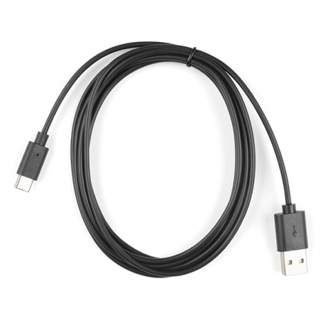
To follow along with this guide you will need at least one USB-C cable to connect the Thing Plus to your computer:
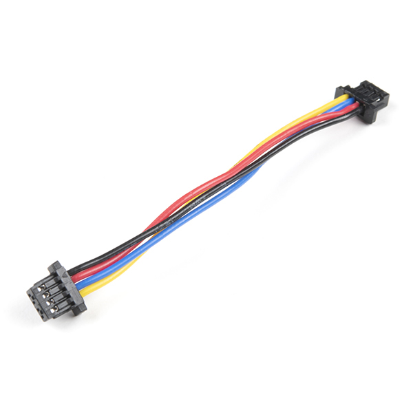
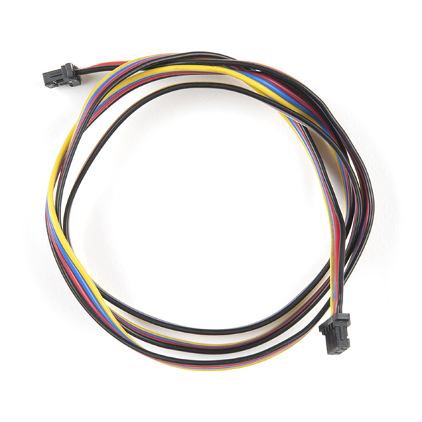
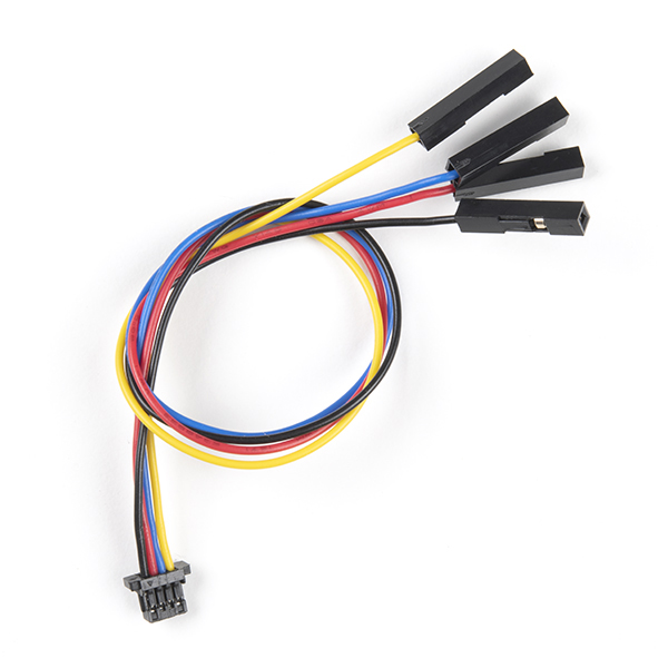
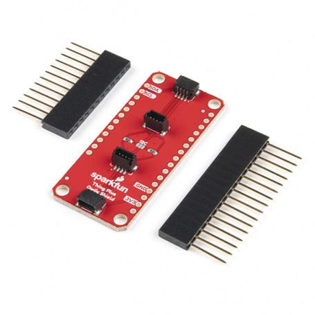
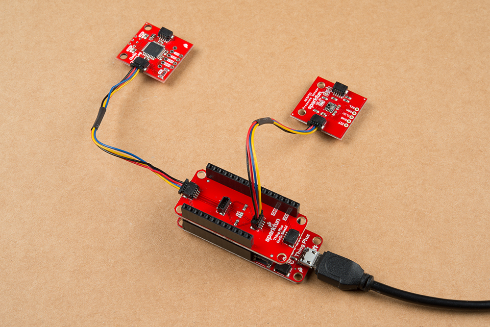
You may also want to get a Qwiic cable or kit to connect the Thing Plus - ESP32-C6 to other Qwiic devices:
Optional Materials
The Thing Plus - ESP32-C6 includes a 2-pin JST connector and integrated charging circuit for an attached single-cell LiPo battery. Below are a few options we recommend for battery-powered applications:
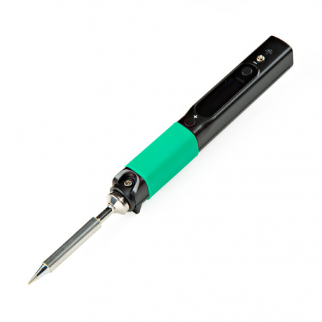
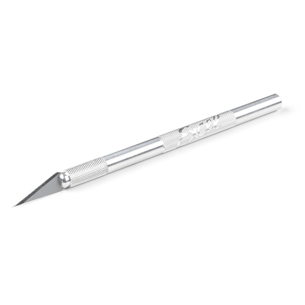
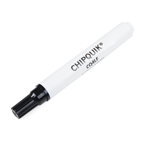
If you prefer a soldered connection or want to modify the solder jumpers on this board, you may need some of the products listed below:
Suggested Reading
We designed this board for integration into SparkFun's Qwiic connect system. Click on the banner below to learn more about the SparkFun Qwiic Connect System.
Before getting started with this Hookup Guide, you may want to read through the tutorials below if you are not familiar with the concepts covered in them or want a refresher. If you are using either of the Qwiic Shields linked above, we recommend reading through their respective Hookup Guides before continuing with this tutorial:
Hardware Overview
Let's take a closer look at the ESP32-S3 module and other hardware present on this Thing Plus board.
ESP32-S3 Module
This Thing Plus uses the ESP32-S3-MINI1 wireless module from espressif. The ESP32-S3 is built around the extremely powerful Xtensa® dual-core 32-bit LX7 microprocessor with a wireless stack that supports 2.4 GHz WiFi and Bluetooth® 5 (LE) with an integrated PCB antenna.
The ESP32-S3-MINI1 offers an impressive peripheral features set including UART, I2C, I2S, SPI, LCD, Camera Interface, LED PWM, SDIO host, two-wire automotive interface (TWAI®) that is compatible with ISO 11898-1/CAN Spec 2.0 and more. This Thing Plus uses the ESP32-S3-MINI1-N4R2 which features 4MB Quad SPI Flash memory and 2MB of PSRAM (Pseudo-static RAM). The ESP32-S3 also has a full-speed USB 2.0 On-The-Go (OTG) interface for USB communication so it does not need any external UART-to-USB conversion.
Power Components
The Thing Plus ESP32-S3 includes several options for powering including USB-C, LiPo battery with on-board battery charging and monitoring circuits as well as direct power inputs.
USB-C Connector
The USB-C connector on the board acts as the primary serial interface for the ESP32-S3 module as well as a power input. It connects directly to the ESP32-S3's USB serial converter. The 5V USB input voltage is regulated down to 3.3V through a voltage regulator with a max current of 500mA@3.3V.
2-Pin JST Connector, Battery Charger, & Fuel Gauge
The board has a 2-pin JST connector to connect a single-cell Lithium Ion (LiPo) battery for battery-powered applications. It also has an MCP73831 battery charger to charge an attached battery and a MAX17048 fuel gauge to monitor battery voltage levels. The charge rate is set to 214mA@3.3V. The MCP73831 receives power from the V_USB line so it only is powered when 5V is provided either over USB or the V_USB PTH pin. If applying voltage directly to the V_USB pin make sure it does not exceed 5.5V.
The MAX17048's I2C lines are pulled up to 3.3V_P to allow for customizable power options. Read on below for more information about peripheral power.
Peripheral Power Control
The board includes a second RT9080 3.3V regulator to control power to the peripheral 3.3V (3.3V_P) rail. This is powered on by default with some options for user control to help conserve power. The RT9080's EN (Enable) pin is tied to ESP45 so users can drive it LOW in their code to disable this line. It also is tied to the main 3.3V rail through the LP_CTL solder jumper so it defaults to powered on. If this solder jumper is opened, it defaults to off when the ESP32-S3 is power-cycled though users can drive the ESP45 pin HIGH in their code to enable the 3.3V_P rail.
Pinout & Qwiic Connector
Thing Plus boards break out a large number of GPIO and interface pins to a pair of 0.1"-spaced plated through-hole (PTH) headers and also has a Qwiic connector for easy integration into SparkFun's Qwiic ecosystem.
Qwiic Connector
The Qwiic connector is tied to the ESP32-S3's I2C bus (IO8/SDA and IO9/SCL). The Qwiic connector provides connections for SDA, SCL, 3.3V, and Ground. Note, the Qwiic connector power and I2C pins are tied to 3.3V_P and are powered by default but if the peripheral power control circuit is adjusted as covered above, it will not function properly without enabling 3.3V_P through code.
PTH Headers
The Thing Plus's pair of PTH headers break out a selection of 21 GPIO pins from the ESP32-S3 along with PTH connections to USB voltage (5V), regulated 3.3V, battery voltage, ESP32 reset signal, and the voltage regulator Enable pin.
Nearly all of the GPIO pins can function in multiple configurations though some of them have more capabilities than others and some are limited to fewer functions. Pins labeled 10, 14, 15, 16, 17, and 18 are all analog capable and also work as capacitive touch inputs. The pins labeled for UART (RX/TX), I2C (SDA/SCL), and SPI (POCI, PICO, & SCK) work primarily for their labeled functions but can be altered for other uses. Refer to the datasheet datasheet for complete information on the pin functionality.
µSD Card Slot
The board has a µSD card slot that connects to the ESP32-S3's SDIO-4 pins. It is a fricton-fit connector so no "clicking" and "unclicking" is necessary. Just plug it in nice and snug.
We chose to connect the SD card to the SDIO interface instead of the dedicated SPI bus as we found it to be reliably faster for read/write speeds averaging roughly 2-3MB/s (read) and ~5-7MB/s (write) though speeds vary depending on the card used. One thing to note about this connector is the SD Card Detect pin is pulled to Ground (LOW) with no card present and shorts to 3.3V (HIGH) with a card inserted. Read on to the "Arduino Examples" section for an example of how to monitor and read this pin.
Buttons
There are two buttons on the board labeled RESET and BOOT. The RESET button is tied to the ESP32-S3's Enable (EN) pin and resets the module when pressed. The BOOT button puts the ESP32-S3 into bootloader mode when held down during power on or reset.
LEDs
This Thing Plus has three standard LEDs labeled PWR, CHG, STAT, and a WS2812 RGB LED next to the ESP32-S3 module on the top of the board. The red Power (PWR) LED indicates whenever the 3.3V circuit is powered. The yellow Charge (CHG) LED indicates whenever the MCP73831 is charging a connected LiPo battery. The green Status (STAT) LED is tied to IO0. The WS2812 RGB LED connects the LED's Data In signal to IO46.
Solder Jumpers
The board has three solder jumpers labeled PWR, CHG, and LP_CTL. The PWR jumper completes the circuit for the Power LED and is CLOSED by default. Open it to disable the Power LED. The CHG jumper completes the circuit for the Charge LED and is CLOSED by default. Open the solder jumper to disable the Charge LED.
The LP_CTL jumper controls how the Low Power and Peripherals power works. It is CLOSED by default to pull the power the RT9080 3.3V regulator's enable pin HIGH to enable peripheral power on the 3.3V_P rail. When opened, the regulator's enable pin connects directly to ESP32 IO45 for users to control manually. Refer to "Peripheral Power Control" above for more information.
Board Dimensions
This board matches the Thing Plus footprint and measures 2.30" x 0.90" (58.42mm x 22.86mm) with four mounting holes that fit a 4-40 screw though the top two mounting holes are slightly obstructed by the ESP32-S3 module so using those can be a bit troublesome.
Hardware Assembly
Now that we're familiar with the hardware on this Thing Plus board, it's time to connect it to our computer or battery power.
Basic USB Assembly
Basic assembly of the Thing Plus ESP32-S3 only requires a USB-C cable connecting the board to a computer. Just plug the cable into the USB-C connector and move on to the Software Setup section. When powered up for the first time, the RGB LED on the "top-right" of the board should be cycling through a rainbow color similar to the video below:
Note
Your computer may not recognize the board as a known USB device if you have not installed the espressif boards package in Arduino and/or installed the espressif IDF.
Battery Assembly
If you prefer a battery-powered application, plug a single-cell LiPo battery into the 2-pin JST connector on the underside of the board like the photo below. Remember, the MCP73831 only charges the battery when V_USB has voltage present either from the USB-C connector or through the V_USB PTH pin.
For tips on the proper use of a LiPo battery and the 2-pin JST connector, please read through our Single Cell LiPo Battery Care tutorial.
Soldered Assembly
Those who prefer a traditional soldered assembly should solder wires or header pins to the PTH header on the side of the board. If you're not familiar with through-hole soldering or would like a refresher, take a look at our Through-Hole Soldering Tutorial:
Software Setup
Attention
If this is your first time using Arduino, please read through our tutorial on installing the Arduino IDE. If you have not installed an Arduino library before, we recommend you check out our installation guide.
With the ESP32-S3 Thing Plus connected to our computer, it's time to set up the boards package in Arduino.
Installing espressif Arduino Boards
To install the ESP32 boards package, open the Preferences menu by navigating to File > Preferences. Look at the bottom of the Preferences menu for "Additional boards manager URLS" and then copy this JSON link into that field:
https://espressif.github.io/arduino-esp32/package_esp32_dev_index.json
Click "Ok" and then open the Boards Manager tool, search for "espressif ESP32" and install the latest alpha release (3.0.0-alpha2 or later). This install process may take some time so feel free to step away while it downloads and installs.
Optional Arduino Libraries
Most of the examples we cover in the next section use existing libraries included with the ESP32 Arduino core but the RGB LED example uses the FastLED library so you'll need it installed to follow along with that example. Navigate to the "Libraries" menu on the left side of the screen, search for "FastLED", and install the latest version. If you prefer to manually install the library, you can download a ZIP of the library by clicking the button below:
espressif IDF
Users who prefer to use espressif's development toolkit, espressif IDF, can get started by following their instructions here and ESP32-S3 specific documentation here.
Arduino Examples
icon: simple/arduino
Now that we've installed the espressif boards package in Arduino, it's time to upload our first sketch to make sure everything installed and is working properly.
Thing Plus ESP32-S3 Github Repository
We've written a few example sketches for this specific board that live in the Github repository that we recommend taking a look at as they demonstrate some important hardware use cases. You can download it from the link above or you can get a ZIP of the library by clicking the button below:
esptool Upload Errors
Some users may run into this upload error related to esptool:
esptool.py v4.5.1 Serial port COM33 Connecting....
A serial exception error occurred: Write timeout Note: This error originates from pySerial. It is likely not a problem with esptool, but with the hardware connection or drivers. For troubleshooting steps visit: https://docs.espressif.com/projects/esptool/en/latest/troubleshooting.html the selected serial port For troubleshooting steps visit: https://docs.espressif.com/projects/esptool/en/latest/troubleshooting.html does not exist or your board is not connected
This error means the board is not entering ROM bootloader mode automatically, causing the upload to hang and fail. We found this relates specifically to esptool.py v4.5.1 in the current stable release of the ESP32 Boards Package (2.0.11). Users can work around this error with one of the following three fixes:
- Use the alpha release (3.0.0 alpha3) of the ESP32 Boards Package. This release updates to esptool.py v4.6.
- Download the latest release of esptool.py from the GitHub repository releases and then manually replace it in the espressif boards package folder.
- If you want to keep using the current full release and encounter this error, force the board to enter the bootloader by holding the BOOT button down, clicking the RESET button, and then releasing the BOOT button.
Board Settings
As mentioned in the previous section, the Thing Plus ESP32-S3 is not currently included in the ESP32 Boards Package so we recommend selecting "ESP32S3 Dev Module" for your board with the following settings:
- USB Mode: Hardware CDC and JTAG
- USB CDC on Boot: Enabled
- Upload Mode: UART0 / Hardware CDC
- PSRAM: QSPI PSRAM
This does require some manual definition/setup for pins in the code which the examples below demonstrate for some of the main peripheral components (Qwiic, µSD card, etc.).
RGB LED
This example uses the FastLED library to cycle the RGB LED on the Thing Plus through a rainbow. Open the code from your downloaded copy of the GitHub repository or copy the code below into a blank sketch. Make sure the FastLED Library is installed, select the board (ESP32S3 Dev Module) and the Port, and click the "Upload" button.
RGB LED Example
/*
  Control Addressable RGB LED
  By: Nathan Seidle
  SparkFun Electronics
  Date: January 13, 2024
  License: MIT. Please see LICENSE.md for more information.

  This example shows how to illuminate the RGB on the SparkFun ESP32 S3 Thing Plus.

  Feel like supporting open source hardware?
  Buy a board from SparkFun!
  SparkFun ESP32-S3 Thing Plus (DEV-24408) https://www.sparkfun.com/products/24408

  Select the following in the Arduino IDE:
  Board: ESP32S3 Dev Module
  USB Mode: Hardware CDC and JTAG
  USB CDC on Boot: Enabled
  Upload Mode: UART0 / Hardware CDC
  PSRAM: QSPI PSRAM
  Port: Select the COM port that the device shows up on under device manager
*/

#include <FastLED.h> // http://librarymanager/All#FastLED

#define LED_PIN     46 //Pin 46 on Thing Plus C S3 is connected to WS2812 LED
#define COLOR_ORDER GRB
#define CHIPSET     WS2812
#define NUM_LEDS    1

#define BRIGHTNESS  25

CRGB leds[NUM_LEDS];

void setup()
{
  Serial.begin(115200);
  //while (Serial == false); //Wait for serial monitor to connect before printing anything

  FastLED.addLeds<CHIPSET, LED_PIN, COLOR_ORDER>(leds, NUM_LEDS).setCorrection(TypicalLEDStrip);
  FastLED.setBrightness(BRIGHTNESS);
}

void loop()
{
  leds[0] = CRGB::Red;
  FastLED.show();
  delay(200);

  leds[0] = CRGB::Green;
  FastLED.show();
  delay(200);

  leds[0] = CRGB::Blue;
  FastLED.show();
  delay(200);

  leds[0] = CRGB::Black;
  FastLED.show();
  delay(100);

  leds[0] = CRGB::White;
  FastLED.show();
  delay(2000);

  leds[0] = CRGB::Black;
  FastLED.show();
  delay(100);
}
I2C Scanner Power Control
This example shows how to toggle the peripheral power voltage supply on and off as well as scan for any I2C devices connected to the I2C bus/Qwiic connector. After uploading, open the serial monitor with the baud set to 115200 and you should see a serial printout of the Fuel Gauge at 0x32 as well as any other devices connected to the Qwiic connector like the screenshot below shows. If you have a Qwiic board plugged in you should see the power LED on it blinking every second as the bus is powered on and off.
I2C Scanner Power Control Example
/*
  Enable Qwiic Power Control
  By: Nathan Seidle
  SparkFun Electronics
  Date: January 13, 2024
  License: MIT. Please see LICENSE.md for more information.

  This shows how to control the power to the Qwiic connector. This example also shows the
  Fuel Gauge IC at address 0x36.

  Feel like supporting open source hardware?
  Buy a board from SparkFun!
  SparkFun ESP32-S3 Thing Plus (DEV-24408) https://www.sparkfun.com/products/24408

  Select the following in the Arduino IDE:
  Board: ESP32S3 Dev Module
  USB Mode: Hardware CDC and JTAG
  USB CDC on Boot: Enabled
  Upload Mode: UART0 / Hardware CDC
  PSRAM: QSPI PSRAM
  Port: Select the COM port that the device shows up on under device manager
*/

#include <Wire.h>

int pin_qwiicPower = 45; //Thing Plus S3 45 is connected to the v-reg that controls the Qwiic power

void setup()
{
  Serial.begin(115200);
  while (Serial == false); //Wait for serial monitor to connect before printing anything

  Serial.println("I2C Scanner");

  //By default the Qwiic power is on. But it can be controlled.
  pinMode(pin_qwiicPower, OUTPUT);
  digitalWrite(pin_qwiicPower, HIGH);

  qwiicPowerOff();
  delay(2000); //Power LED on a Qwiic board should now be off

  qwiicPowerOn();

  Wire.begin();
}

void loop()
{
  //Toggle the power on the Qwiic connector

  Serial.println();
  for (byte address = 1; address < 127; address++ )
  {
    Wire.beginTransmission(address);
    if (Wire.endTransmission() == 0)
    {
      Serial.print("Device found at address 0x");
      if (address < 0x10)
        Serial.print("0");
      Serial.println(address, HEX);
    }
  }
  Serial.println("Done");
  delay(100);
}

void qwiicPowerOff()
{
  digitalWrite(pin_qwiicPower, LOW);
}

void qwiicPowerOn()
{
  digitalWrite(pin_qwiicPower, HIGH);
}
SD Card Detect
The SD Card Detect example is a simple example that monitors the card detect pin on the µSD card slot. As mentioned in the Hardware Overview section, the card detect switch is normally open and closed with a card inserted so the switch goes to VDD (3.3V). This requires us to set up an internal pull-down for card detection to work properly.
After uploading, you can open the serial monitor with the baud set to 115200 and it should print out either "Card Inserted" or "No SD Card" depending on whether or not a µSD card is present.
SD Card Detect Example
/*
  Detecting if an SD Card is present
  By: Nathan Seidle
  SparkFun Electronics
  Date: January 13, 2024
  License: MIT. Please see LICENSE.md for more information.

  The socket detect switch is normally open, and closed when a card is inserted.
  The switch is connected to VDD, so when a card is inserted, the switch is connected
  to 3.3V. Therefore, we use an internal pull down.

  This shows how to control the power to the Qwiic connector. This example also shows the
  Fuel Gauge IC at address 0x36.

  Feel like supporting open source hardware?
  Buy a board from SparkFun!
  SparkFun ESP32-S3 Thing Plus (DEV-24408) https://www.sparkfun.com/products/24408

  Select the following in the Arduino IDE:
  Board: ESP32S3 Dev Module
  USB Mode: Hardware CDC and JTAG
  USB CDC on Boot: Enabled
  Upload Mode: UART0 / Hardware CDC
  PSRAM: QSPI PSRAM
  Port: Select the COM port that the device shows up on under device manager
*/

int pin_sdDetect = 48;

void setup()
{
  Serial.begin(115200);
  while (Serial == false); //Wait for serial monitor to connect before printing anything
  Serial.println("SDIO test");

  pinMode(pin_sdDetect, INPUT_PULLDOWN);
}

void loop()
{
  if (Serial.available()) ESP.restart();

  if (digitalRead(pin_sdDetect) == HIGH)
    Serial.println("Card inserted");
  else
    Serial.println("No SD card");

  delay(500);
}
PSRAM Test
This example demonstrates how to enable and use PSRAM for RAM requests above a 1,000 byte threshold. The setup initializes PSRAM and prints out whether or not this was successful and then prints out available PSRAM space.
PSRAM Test Example
/*
  Enable PSRAM on the ESP32-S3
  By: Nathan Seidle
  SparkFun Electronics
  Date: January 13, 2024
  License: MIT. Please see LICENSE.md for more information.

  This example shows how to enable PSRAM on ESP32-S3 modules that have it, and use it for
  RAM requests above a certain byte threshold.

  Note: Not all ESP32 modules have PSRAM built-in. The SparkFun ESP32-S3 uses the
  ESP32-S3 Mini N8R2 with 8MB flash and 2MB PSRAM.

  Feel like supporting open source hardware?
  Buy a board from SparkFun!
  SparkFun ESP32-S3 Thing Plus (DEV-24408) https://www.sparkfun.com/products/24408

  Select the following in the Arduino IDE:
  Board: ESP32S3 Dev Module
  USB Mode: Hardware CDC and JTAG
  USB CDC on Boot: Enabled
  Upload Mode: UART0 / Hardware CDC
  PSRAM: QSPI PSRAM
  Port: Select the COM port that the device shows up on under device manager
*/

unsigned long lastHeapReport;

void setup()
{
  Serial.begin(115200);
  while (Serial == false); //Wait for serial monitor to connect before printing anything

  if (psramInit() == false)
    Serial.println("PSRAM failed to initialize");
  else
    Serial.println("PSRAM initialized");

  Serial.printf("PSRAM Size available (bytes): %d\r\n", ESP.getFreePsram());

  heap_caps_malloc_extmem_enable(1000); //Use PSRAM for memory requests larger than 1,000 bytes
}

void loop()
{
  delay(20);

  if (millis() - lastHeapReport > 1000)
  {
    lastHeapReport = millis();
    reportHeap();
  }

  if (Serial.available()) ESP.restart();
}

void reportHeap()
{
  Serial.printf("FreeHeap: %d / HeapLowestPoint: %d / LargestBlock: %d / Used PSRAM: %d\r\n", ESP.getFreeHeap(),
                xPortGetMinimumEverFreeHeapSize(), heap_caps_get_largest_free_block(MALLOC_CAP_8BIT), ESP.getPsramSize() - ESP.getFreePsram());
}
Troubleshooting Tips
esptool.py v4.5.1 Serial port COM33 Connecting....
A serial exception error occurred: Write timeout Note: This error originates from pySerial. It is likely not a problem with esptool, but with the hardware connection or drivers. For troubleshooting steps visit: https://docs.espressif.com/projects/esptool/en/latest/troubleshooting.html the selected serial port For troubleshooting steps visit: https://docs.espressif.com/projects/esptool/en/latest/troubleshooting.html does not exist or your board is not connected
This error means the board is not entering ROM bootloader mode automatically, causing the upload to hang and fail. We found this relates specifically to esptool.py v4.5.1 in the current stable release of the ESP32 Boards Package (2.0.11). Users can work around this error with one of the following three fixes:
- Use the alpha release (3.0.0 alpha3) of the ESP32 Boards Package. This release updates to esptool.py v4.6.
- Download the latest release of esptool.py from the GitHub repository releases and then manually replace it in the espressif boards package folder.
- If you want to keep using the current full release and encounter this error, force the board to enter the bootloader by holding the BOOT button down, clicking the RESET button, and then releasing the BOOT button.
Digital Reset
Some users may run into an issue when uploading completes where the board does not digitally reset properly. If you notice your code is not running after upload finishes, just press the RESET button on the board and it should start running.
General Troubleshooting
Need Help?
If you need technical assistance or more information on a product that is not working as you expected, we recommend heading on over to the SparkFun Technical Assistance page for some initial troubleshooting.
If you can't find what you need there, the SparkFun Forums is a great place to search product forums and ask questions.
Account Registration Required
If this is your first visit to our forum, you'll need to create a Forum Account to post questions.
Resources:
For more information about the Thing Plus - ESP32-S3, check out the resources below:

