Introduction
-
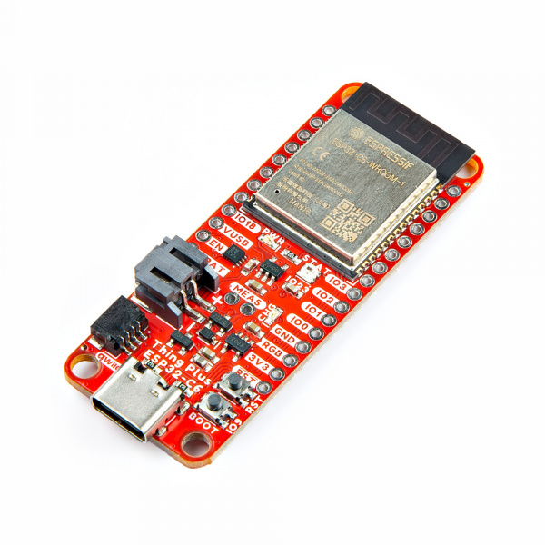
SparkFun Thing Plus - ESP32-C6
SKU: DEV-22924
-
The SparkFun Thing Plus - ESP32-C6 adds a powerful wireless development option to SparkFun's popular Thing Plus footprint. This Thing Plus board features the ESP32-C6 WROOM-1-N16 module from espressif™. It includes a LiPo battery charger and fuel gauge to charge and monitor a battery connected to the on-bard 2-pin JST connector, µSD card slot, an addressable LED and more. The board breaks out all of the ESP32-C6's 23 GPIO pins to a pair of 0.1"-spaced PTH headers on either side of the board. The board also has a USB-C connector for primary power and programming and a Qwiic connector to integrate it into SparkFun's Qwiic ecosystem.
The ESP32-C6 SoC is built around a RISC-V single-core processor with 16 MB flash memory with an integrated wireless stack. The wireless stack supports 2.4 GHz WiFi 6, Bluetooth® 5.3, Zigbee and Thread (802.15.4) and uses an on-board PCB antenna. The ESP32-C6 includes a wide range of peripheral options including SPI, UART, LPUART, I2C, I2S, LED PWM, USB Serial/JTAG controller, ADC and more. Many of these peripherals can be mapped to any GPIO pin though some are tied to specific pins.
Purchase from SparkFun
Required Materials
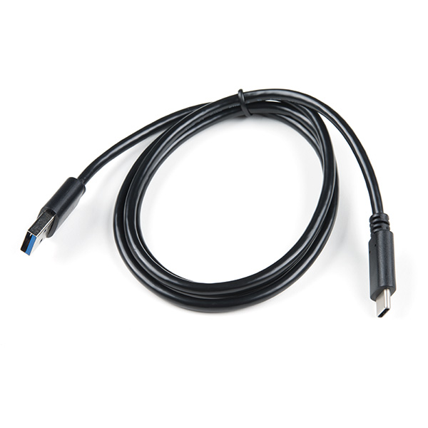
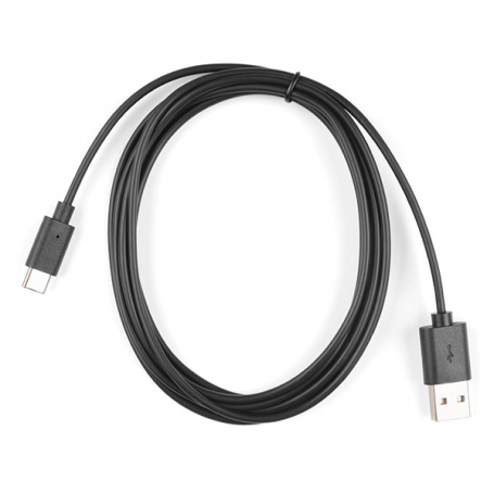
To follow along with this guide you will need at least one USB-C cable to connect the Thing Plus to your computer:
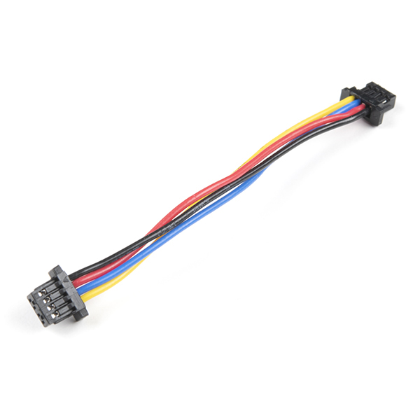
You may also want to get a Qwiic cable or kit to connect the Thing Plus - ESP32-C6 to other Qwiic devices:
Optional Materials
The Thing Plus - ESP32-C6 includes a 2-pin JST connector and integrated charging circuit for an attached single-cell LiPo battery. Below are a few options we recommend for battery-powered applications:


If you prefer a soldered connection or want to modify the solder jumpers on this board, you may need some of the products listed below:
Suggested Reading
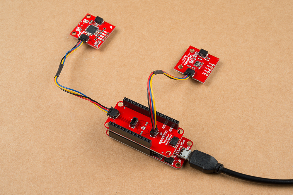
We designed this board for integration into SparkFun's Qwiic connect system. Click on the banner below to learn more about the SparkFun Qwiic Connect System.

Before getting started with this Hookup Guide, you may want to read through the tutorials below if you are not familiar with the concepts covered in them or want a refresher. If you are using either of the Qwiic Shields linked above, we recommend reading through their respective Hookup Guides before continuing with this tutorial:


Hardware Overview
Let's take a closer look at the ESP32-C6 WROOM1 module and other hardware present on this Thing Plus board.
ESP32-C6 WROOM1 Module
The ESP32-C6 WROOM1 module from espressif combines a powerful RISC-5 processor with a wireless stack compatible with most common wireless protocols.

This development board uses the WROOM1 version of the C6 module which has slightly more computing power in exchange for lesser power efficiency. The ESP32-C6 is built around a 32-bit RISC-V single-core processor with an integrated wireless stack. The wireless stack is compatible with 2.4 GHz WiFi 6, Bluetooth® 5.3, Zigbee and Thread (802.15.4) and uses an on-board PCB antenna.
The module features a wide range of peripheral options including SPI, UART, LPUART, I2C, I2S, LED PWM, USB Serial/JTAG controller, ADC and more. Many of these peripherals can be mapped to any GPIO pin though some are tied to specific pins. This Thing Plus breaks out 21 pins from the module to a pair of 0.1"-spaced PTH headers.
The ESP32-C6 has 16 MB Flash memory along with 512 KB SRAM (high power)/ 16 KB SRAM (low power). The module uses pin strapping to configure boot mode parameters. The board defaults to standard mode (GPIO 9 internal pull-up, all other strapping pins floating) but it can be set to other parameters by performing the following pin strapping:
- SDIO Sampling and Driving Clock Edge - MTMS & MTDI
- Chip Boot Mode - GPIO8 & GPIO9
- ROM Code Printing to UART - GPIO8
- JTAG Signal Source - GPIO15
Power Components
The Thing Plus ESP32-C6 includes several options for powering including USB-C, LiPo battery with on-board battery charging and monitoring circuits as well as direct power inputs.

USB-C Connector
The USB-C connector on the board acts as the primary serial interface for the ESP32-C6 module as well as a power input. It connects directly to the ESP32-C6's USB serial converter. The 5V USB input voltage is regulated down to 3.3V through a voltage regulator with a max current of 500mA@3.3V.
2-Pin JST Connector, Battery Charger, & Fuel Gauge
The board has a 2-pin JST connector to connect a single-cell Lithium Ion (LiPo) battery for battery-powered applications. It also has an MCP73831 battery charger to charge an attached battery and a MAX17048 fuel gauge to monitor battery voltage levels over I2C. The charge rate is set to 214mA@3.3V. The MCP73831 receives power from the V_USB line so it only is powered when 5V is provided either over USB or the V_USB PTH pin. If applying voltage directly to the V_USB pin make sure it does not exceed 5.5V.
Pinout & Qwiic Connector
Next up let's take a look at the Thing Plus pinout and Qwiic connector on this board.

PTH Headers
The Thing Plus routes 23 of the ESP32-C6's GPIO pins to a pair of 0.1"-spaced headers on either side of the board. This includes all seven of the 12-bit ADC-capable pins, one UART, one I2C bus (SDA/SCL), one SPI interface (POCI/PICO/SCK), and seven GPIO pins. Some of the GPIO connect to specific functions on the board by default through solder jumpers listed below:
- IO18 - CS
- IO22 - SD Detect
- IO11 - MAX17038 Alert
- IO23 - WS2812 STAT LED Data In
- IO15 - Low Power control
Qwiic Connector
There's a Qwiic connector on the board tied to the ESP32-C6's Low Power I2C bus (I/O pins 6 and 7) for easy integration into SparkFun's Qwiic ecosystem. The Qwiic connector provides connections for SDA, SCL, 3.3V, and Ground.
Buttons
There are two buttons on the board labeled RESET and BOOT. The RESET button is tied to the ESP32-C6's Enable (EN) pin and resets the module when pressed. The BOOT button puts the ESP32-C6 into bootloader mode when held down during power on or reset.

µSD Card Slot
This board also has a friction-fit µSD card slot for users who need more storage space on the Thing Plus - ESP32-C6.

The slot connects the SD card's communication interface to the ESP32-C6's SPI interface using the following pins:
- SD Serial Data Out: IO21/POCI
- SD Serial Data In: IO20/PICO
- SD Serial Clock: IO19/SCK
- SD Chip Select: IO18/CS
- SD Detect: IO22/SD_DET
LEDs
This Thing Plus has three LEDs labeled PWR, CHG, and STAT. The red Power (PWR) LED indicates whenever the 3.3V circuit is powered. The yellow Charge (CHG) LED indicates whenever the MCP73831 is charging a connected LiPo battery. The WS2812 RGB Status (STAT) LED connects the LED's Data In signal to IO23.

RGB LED
The board definition for the Thing Plus - ESP32-C6 sets IO23 to use espressif's RGB_BUILTIN code support. This automatically includes the necessary code to control an RGB LED easily when calling RGB_BUILTIN. Unfortunately, this means the RGB PTH pin (IO23) can run into code conflicts when users attempt to use it for another purpose. If you really need IO23 for something other than the RGB LED, you may need to modify the board definition files in the ESP32 Arduino boards package. Modifying these files is beyond the scope of this tutorial and is not supported by SparkFun.
Solder Jumpers
There are nine solder jumpers on the Thing Plus - ESP32-C6 labeled I2C, ALRT, SD_DET, MEAS, LP, SHLD, RGB, CHG, and PWR. The table below outlines the jumpers' labels, default state, function, and any notes regarding their use:

| Label | Default State | Function | Notes |
|---|---|---|---|
| I2C | CLOSED | Three-way jumper pulls the SDA/SCL lines to 3.3V through a pair of 2.2kΩ resistors | Open completely to disable pullups on I2C bus if needed |
| ALRT | CLOSED | Ties the MAX17048's alert pin to IO11 for battery voltage monitoring | Open to isolate IO11 from the MAX17048's alert pin if IO11 is needed for other uses |
| SD_DET | CLOSED | Connects the µSD card's card detection pin to IO19 | Open to disable µSD card detection or if IO19 is needed for other uses |
| MEAS | CLOSED | Completes the input voltage circuit from V_USB & V_Batt to the 3.3V regulator | Open to interrupt the circuit to measure current consumed by the board with a digital multimeter |
| LP | See Note | Enables/disables low power control for the ESP32-C6 | Three-way jumper. Defaults to disabled (connects to Ground). Adjust to IO15 side to enable low power control |
| SHLD | CLOSED | Ties the USB-C shield pin to the ground plane | Open to isolate USB-C shield pin from the board's ground plane |
| RGB | Open | Connects WS2812 data out (DO) signal to the No Connect/AREF PTH pin | Open to isolate DO signal from the No Connect/AREF PTH pin to chain with other WS2812 LEDs |
| CHG | CLOSED | Completes Charge LED circuit | Open to disable Charge LED |
| PWR | CLOSED | Completes the Power LED circuit | Open to disable the Power LED |
Board Dimensions
This board matches the Thing Plus footprint and measures 2.30" x 0.90" (58.42mm x 22.86mm) with four mounting holes that fit a 4-40 screw though the top two mounting holes are obstructed by the ESP32-C6 module.

Hardware Assembly
Now that we're familiar with the hardware on this Thing Plus board, it's time to connect it to our computer or battery power.
Basic USB Assembly
Basic assembly of the Thing Plus ESP32-C only requires a USB-C cable connecting the board to a computer. Just plug the cable into the USB-C connector like the photo below shows and you should see the RGB LED cycling through rainbow colors with the pre-loaded test code. From here, we can move on to installing the espressif boards package in Arduino and uploading code.

Note
Your computer may not recognize the board as a known USB device if you have not installed the espressif boards package in Arduino and/or installed the espressif IDF.
Battery Assembly
If you prefer a battery-powered application, plug a single-cell LiPo battery into the 2-pin JST connector on the underside of the board like the photo below. Remember, the MCP73831 only charges the battery when V_USB has voltage present either from the USB-C connector or through the V_USB PTH pin.

For tips on the proper use of a LiPo battery and the 2-pin JST connector, please read through our Single Cell LiPo Battery Care tutorial.
Soldered Assembly
Those who prefer a traditional soldered assembly should solder wires or header pins to the PTH header on the side of the board. If you're not familiar with through-hole soldering or would like a refresher, take a look at our Through-Hole Soldering Tutorial:

Software Setup
Attention
If this is your first time using Arduino, please read through our tutorial on installing the Arduino IDE. If you have not installed an Arduino library before, we recommend you check out our installation guide.
With the ESP32-C6 Thing Plus connected to our computer, it's time to set up the boards package in Arduino.
Installing espressif Arduino Boards
To install the ESP32 boards package, open the Preferences menu by navigating to File > Preferences. Look at the bottom of the Preferences menu for "Additional boards manager URLS" and then copy this JSON link into that field:
https://espressif.github.io/arduino-esp32/package_esp32_dev_index.json
Click "Ok" and then open the Boards Manager tool, search for "espressif ESP32" and install the latest release. This install process may take some time so feel free to step away while it downloads and installs.

espressif IDF
Users who prefer to use espressif's development toolkit, espressif IDF, can get started by following their instructions here and ESP32-C6 specific documentation here.
Arduino Examples
icon: simple/arduino
Now that we've installed the espressif boards package in Arduino, it's time to upload our first sketch to make sure everything is working properly.
Blink RGB Example
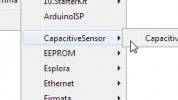
The ESP32 core includes integrated code support for easily controlling a WS2812 LED and an example demonstrating how to cycle an RGB LED like the one found on this Thing Plus so long as the board variant defines it as RGB_BUILTIN. The Thing Plus ESP32-C6 does define IO23 as RBG_BUILTIN so this example and all other code calling for the built-in RGB LED works for this board. Open the example by navigating to File > Examples > ESP32 > GPIO > BlinkRGB like the screenshot below shows:

Select the board (SparkFun Thing Plus - C6) and Port and click "Upload". After uploading you should see the STAT LED on the board turn on full white, turn off, and then cycle through red, green, and blue repeatedly.
USB CDC On Boot Settings
Take note of the option labeled "USB CDC on Boot" when selecting the Board from the Tools menu. This option sets the serial outputs and defines their label for use in code. The SparkFun variants default to Enable USB CDC on boot which sets both Serial and Serial0 as available serial ports. In this configuration, Serial corresponds to the direct USB/Serial converter on the chip (and the USB-C interface) and Serial0 corresponds to the UART0 bus (default pins are 16 and 17).
With either setting, Serial1 is available and refers to the UART1 bus (default pins are 4 and 5).
Troubleshooting Tips
With either setting, Serial1 is available and refers to the UART1 bus (default pins are 4 and 5).
RGB LED Pin
The board definition for the Thing Plus - ESP32-C6 sets IO23 to use espressif's RGB_BUILTIN code support. This automatically includes the necessary code to control an RGB LED easily when calling RGB_BUILTIN. Unfortunately, this means the RGB PTH pin (IO23) can run into code conflicts when users attempt to use it for another purpose. If you really need IO23 for something other than the RGB LED, you may need to modify the board definition files in the ESP32 Arduino boards package. Modifying these files is beyond the scope of this tutorial and is not supported by SparkFun.
General Troubleshooting
Need Help?
If you need technical assistance or more information on a product that is not working as you expected, we recommend heading on over to the SparkFun Technical Assistance page for some initial troubleshooting.
If you can't find what you need there, the SparkFun Forums is a great place to search product forums and ask questions.
Account Registration Required
If this is your first visit to our forum, you'll need to create a Forum Account to post questions.
Resources:
For more information on the Thing Plus ESP32-C6, check out the resources below: