Introduction
The SparkFun Thing Plus - NORA-W306 is a Feather form-factor development board equipped with the u-blox NORA-W306 module. The module contains a Realtek RTL8720DF, which has an integrated single-chip low-power dual-band (2.4GHz and 5GHz) Wireless LAN (WLAN) and Bluetooth® Low Energy (BLE 5.3) communication microcontroller. It also consists of a dual processor core: Arm Cortex-M33 and Cortex-M23. To complement the module's low-power options, we've optimized components and added the ability to depower all subsystems to conserve as much power as possible for remote battery-powered applications.
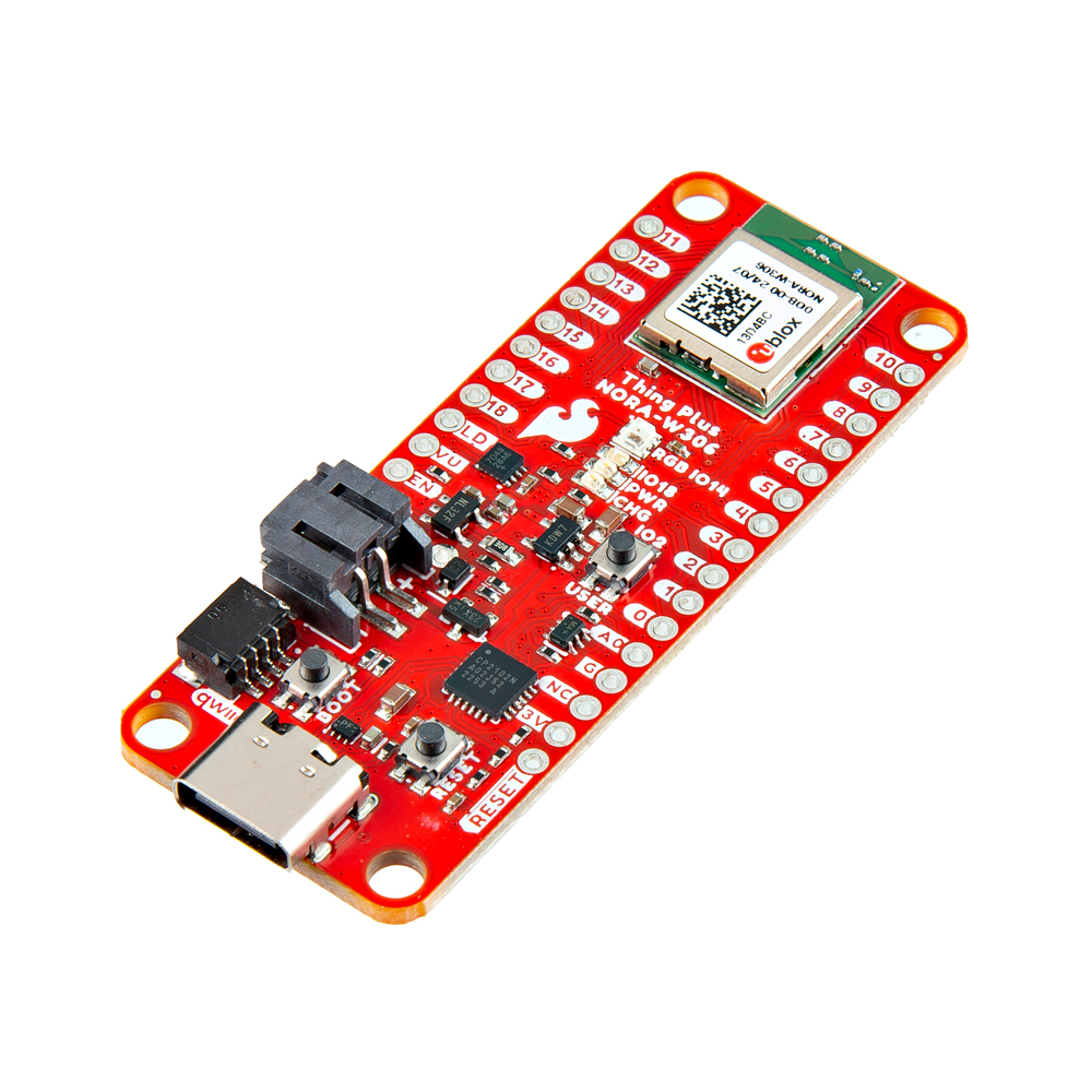
In this tutorial, we'll go over the hardware and how to hookup the development board to an Arduino. We will also go over a few Arduino examples to get started!
Required Materials
To follow along with this tutorial, you will need the following materials. You may not need everything though depending on what you have. Add it to your cart, read through the guide, and adjust the cart as necessary.
Note
Make sure that you have a microSD card reader or adapter as well to read the contents saved on the memory card.
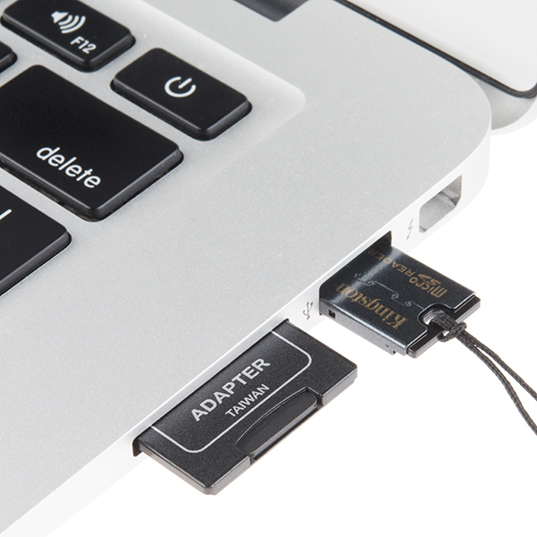 |
| MicroSD Card Adapters |
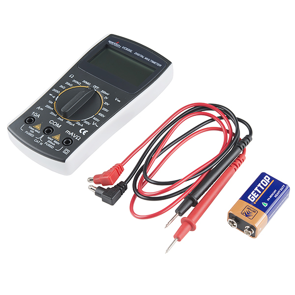
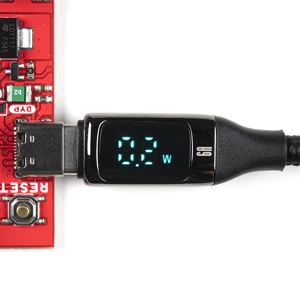
Tools (Optional)
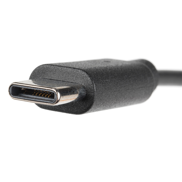
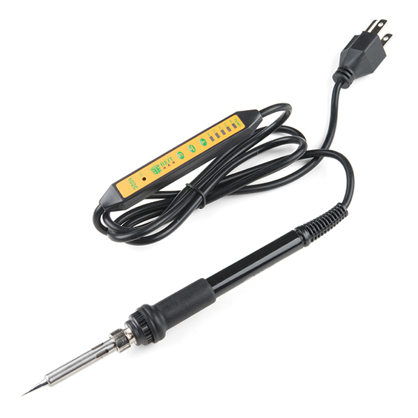
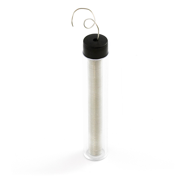
You will need a soldering iron, solder, and general soldering accessories for a secure connection when using the plated through holes. For users that are measuring the current draw, you may want to consider grabbing a digital multimeter or a USB C cable that is able to display the current draw.


Prototyping Accessories
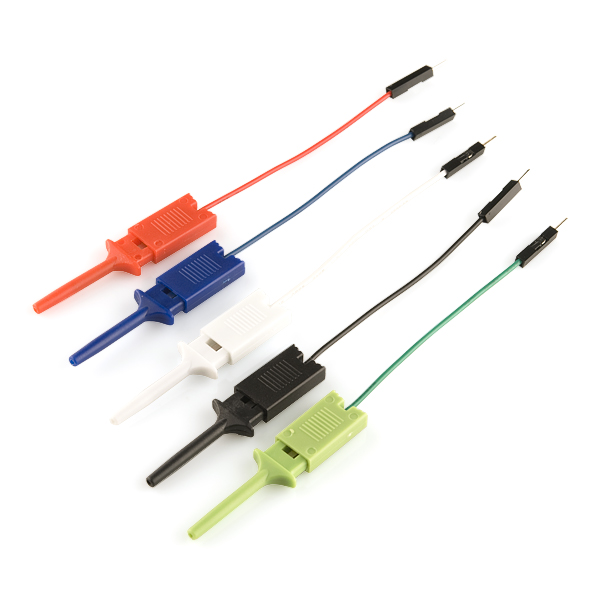
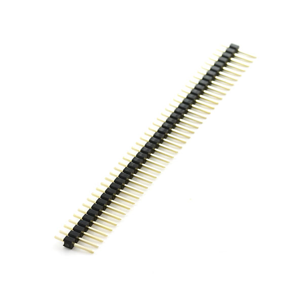
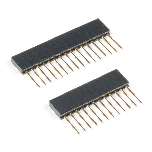
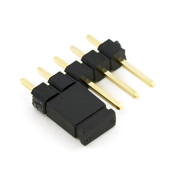
Depending on your setup, you may want to use IC hooks for a temporary connection. However, you will want to solder header pins to connect devices to the plated through holes for a secure connection.
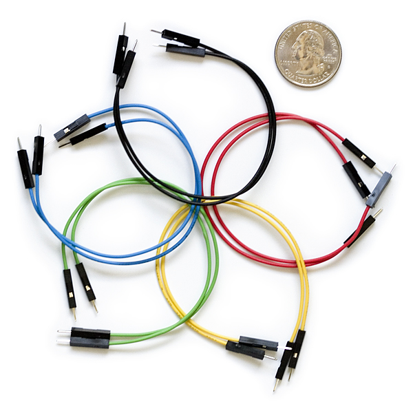
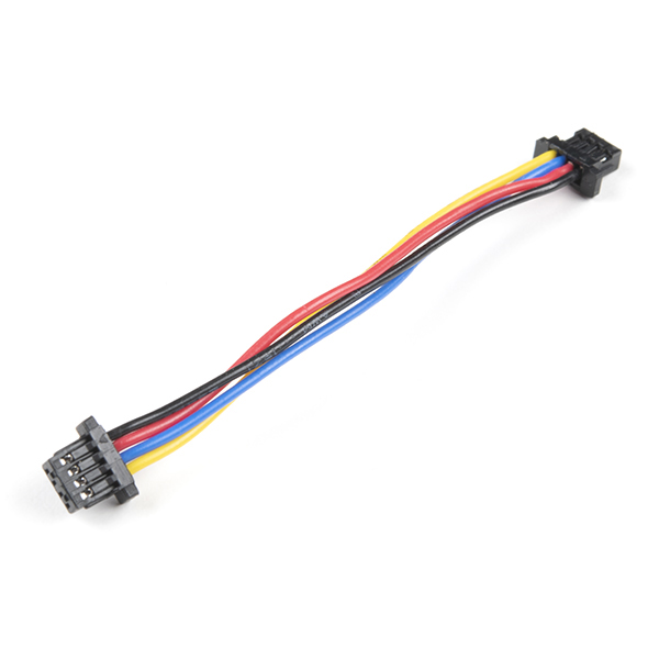
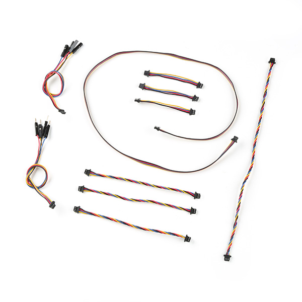
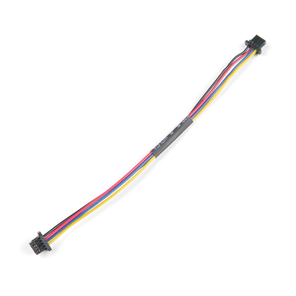
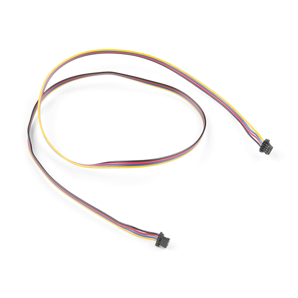
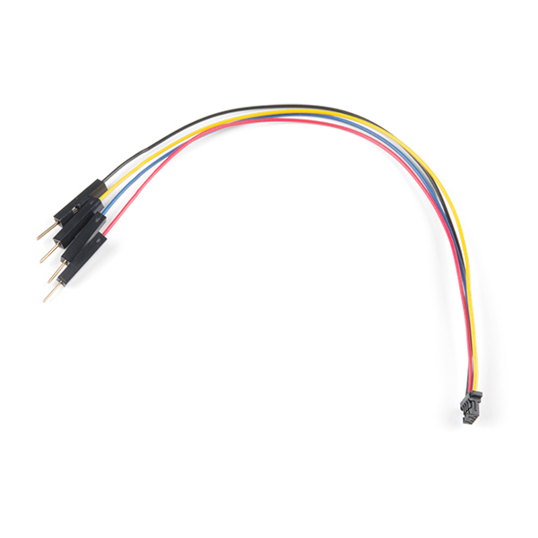
Qwiic Cables
For those that want to take advantage of the Qwiic enabled devices, you'll want to grab a Qwiic cable.
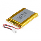
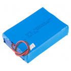
LiPo Battery
A single-cell Lithium-ion battery can be connected to the SparkFun Thing Plus NORA-W306 for portability.

Suggested Reading
If you aren't familiar with the Qwiic Connection System, we recommend reading here for an overview.

If you aren’t familiar with the following concepts, we also recommend checking out a few of these tutorials before continuing.


Hardware Overview
In this section, we will highlight the hardware and pins that are broken out on the SparkFun Thing Plus NORA-W306. For more information, check out our Resources and Going Further for the u-blox NORA-W306 module or Realtek RTL8720DF that is contained within the module.
 |
 |
| Top View | Bottom View |
Power
There are a variety of power and power-related nets broken out to connectors and through hole pads. Power is regulated down to 3.3V for the NORA-W306 so the logic level is 3.3V. There are Schottky diode and transistors to safely select voltage from the USB or LiPo battery. This avoids any conflicting voltages between the two sources.
- VU or VUSB — The V_BUS net is connected to the USB Type C connector and the VU/VUSB PTH. You can use 5V from a USB port by connecting to the USB Type C connector or connecting power to the VBUS PTH. Make sure that power you provide to this pin does not exceed 6 volts. Power is regulated down with the XC6222 3.3V/700mA voltage regulator. The USB Type C connector is also used to upload code to your processor, send serial data to a terminal window, or charging the LiPo battery. Of course for portable power, you could connect a USB battery as an alternative to using a LiPo battery.
- VB — The V_BATT net is connected to the 2-pin JST style connector, VB PTH, and the NORA-W306's MEAS pin. For portable applications, you can connect a nominal 3.7V single cell, LiPo battery to the 2-pin JST style connector. This pin is also connected to the MCP73831 charge IC to safely charge the LiPo battery to its maximum voltage of about 4.2V. We recommend connecting only LiPo batteries to the VBAT net to power the board. Of course, you can power a separate device through the VBAT PTH pin. Power is regulated down with the XC6222 3.3V/700mA voltage regulator.
- 3V or 3V3 — The 3.3V net is labeled as 3V or 3V3. You can apply power to the board if you have a regulated voltage of 3.3V. Otherwise, you could power a separate device through the 3V3 PTH pin. This is also connected to the Qwiic connector's 3.3V pin to power Qwiic enabled devices.
- EN — The 3.3V voltage regulator's EN pin is labeled as EN. Pulling this pin low will disable the 3.3V voltage regulator.
- G or GND — Of course, is the common, ground voltage (0V reference) for the system.
 |
 |
| Power, Ground, and Connectors Highlighted (Top & Bottom View) |
|
Note
You will notice the pads of the SWD pins are also highlighted! 3.3V and ground are also connected to these pads. Users can easily access these pins using a SWD header and cable. Of course, you could also solder wire to those pads if you needed another way to connect to the traces.
Tip
To complement the module's low-power options, we've optimized components and added the ability to depower all subsystems to conserve as much power as possible for remote battery-powered applications. Without a battery attached or charging, and cutting the power to WS2812 (i.e. jumper JP3); the current draw was as low as 14µA in low power mode! Amazing! Under normal conditions, we measured the current draw as low as 30mA.
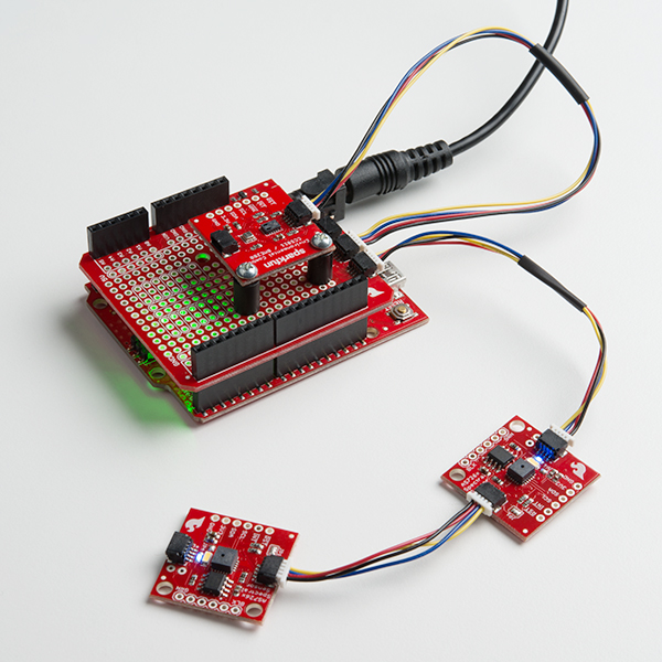
Let's compare the Thing Plus ESP32 (USB-C) against the Thing Plus NORA-W306. The power LED jumper was cut on the Thing Plus ESP32. A microSD card was inserted in the microSD card socket (which does not have a way to turn off power through a GPIO) and the board was powered via a single cell LiPo battery. The current draw was 884µA in deep sleep mode while it was 40mA when awake.
For the Thing Plus NORA-W306, we cut the power LED and WS28112 LED jumpers. The SDPC (microSD Power Control) jumper was modified so power to the microSD card can be controlled through GPIO 17. A microSD card was inserted in the microSD card socket. With the MEAS jumper cut, a multimeter (set to measure current) was connected to monitor the current draw. Power was also provided via a single cell LiPo battery. The current draw was 115µA in deep sleep mode while it was 21mA when awake.
For more information, check out the demo video below with current draw for the board in low power mode!
LiPo Charge Circuit
The board includes the MCP73831 LiPo charger IC (the little black IC with 5 pins highlighted) to safely charge a single cell, LiPo battery. In this case, the charge rate is set to a default rate of 500mA. Cutting the trace on the back while adding a solder jumper between the middle pad and the pad labeled as 100mA will set the charge rate to 100mA. The on-board LED (not highlighted) labeled as CHG can be used to get an indication of the charge status of your battery.
 |
| 2-pin JST Style Connector, LiPo Charger IC, and VBATT PTH Highlighted (Top View) |
Note
For more information on proper handling of LiPo batteries, check out the tutorial on Single Cell LiPo Battery Care.
GPIO
The SparkFun Thing Plus - NORA-W306 breaks out the GPIO pins to plated through hole pads on the edge of the board using the Thing Plus/Feather Form Factor. Each of the pins on the edge of the board are tired to various components on the board. Check below for more information on each connection!
 |
 |
| GPIO Pins Highlighted (Top & Bottom View) |
|
Note that the pin label might have additional functionality that may not be apparent from the silkscreen. Below is a graphical datasheet of the SparkFun Thing Plus - NORA-W306 that highlights the additional functionality.
 |
| Graphical Datasheet |
Note
While the u-blox integration manual may have pins highlighted to show additional functionality, there are some that are not supported in the Realtek's Arduino core. Some of these features that are not supported in the Arduino core include SDIO, I2S, IR, and RTC.
SWD
For advanced users, the SWD pins are broken out on the 2x5 header on the back of the board. Note that this is not populated so you will need to solder a compatible header, 2x5 SWD cable, and compatible JTAG programmer to connect. These pins are also connected to the edge of the board.
 |
| SWD Pins Highlighted |
Note
Pin 10 is tied to the SWD Data pad and A0 is tied to SWD CLK pad on the back of the board.
Reset and Boot Buttons
Each board includes a RESET and BOOT button. There is an additional reset PTH next to the reset button. Hit the reset button to restart the NORA-W306. To manually place the NORA-W306 into boot mode, hold down the BOOT button while pressing the RESET button momentarily and then release the BOOT button.
 |
 |
| Reset and Boot Pins and Buttons Highlighted (Top & Bottom View) |
|
Note
The BOOT button is also connected to pin 0 (TX). The datasheet refers to this pin as the CHIP_EN.
Note
You will notice a pad of the SWD is also highlighted. The reset pin is connected to this pad. Users can easily access these pins using a SWD header and cable. Of course, you could also solder wire to those pads if you needed another way to connect to the traces.
User Button
The board also includes a user button that is connected pin 2.
 |
 |
| Reset & Boot Pins and Buttons Highlighted (Top & Bottom View) |
|
Note
When defining the pin for the user button, make sure to use an internal pull-up resistor so that the button is not floating.
Tip
Need a bigger button? Users can connect pin 2 on the edge of the board to an external button!
Interrupts
Speaking of buttons, all GPIOs can also be set as interrupts!
|
|
| Interrupt Pins Highlighted (Top & Bottom View) |
|
UART
There are two UARTs. The primary hardware UART (UART0) is connected to the USB-to-serial converter. The secondary hardware UART (UART1) is broken out to the edge of the board. We recommend connecting a UART device to the secondary hardware UART to avoid any bus contention with the CP2102N.
 |
 |
| UARTs Highlighted (Top & Bottom View) |
|
CP2102N USB-to-Serial Converter
The board includes the CP2102N USB-to-Serial converter. This is used for serial programming or communicating with a serial terminal. The CP2102N is connected to the NORA-W306's primary hardware UART (UART0): TX pin is connected to pin 0 (RX0) while and RX pin is connected to pin 1 (TX0).
 |
 |
| USB-to-Serial Converter, USB, and UART0 Highlighted (Top & Bottom View) |
|
Qwiic and I2C
The board includes one horizontal Qwiic connector on the board. These pins are connected to the primary I2C bus and power (e.g. 3.3V and GND) allowing you to easily add a Qwiic-enabled device to your application. The I2C data and clock lines are also tied to 2.2kΩ pull-up resistors. The I2C SCL pin is connected to 12. The I2C SDA is connected to 11.
 |
 |
| I2C and Qwiic Connector Highlighted (Top & Bottom View) |
|
LiPo Fuel Gauge - MAX17048
Built into the board is also the single cell LiPo Fuel Gauge, specifically the MAX17408. The 7-bit, unshifted address of the MAX17048 is 0x36. The address becomes 0x6C for write and 0x6D for read.
 |
| LiPo Fuel Gauge - MAX17048 Highlighted (Top View) |
SPI
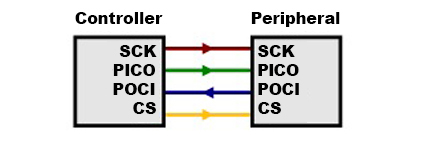
There are two SPI ports available. The primary SPI pins (SPI0) is broken out as: 5 (SPI0_SCK), 6 (SPI0_PICO), 7 (SPI0_POCI), and 4 (SPI0_CS). These are also connected to the microSD card that is populated on the back. The secondary SPI pins (SPI1) is broken out as: 16 (SPI1_SCK), 14 (SPI1_PICO), 13 (SPI1_POCI), and 15 (SPI1_CS)
 |
 |
| SPI Pins Highlighted (Top & Bottom View) |
|
Note
Pin 14 is also connected to the addressable LED. The Realtek Arduino Core needed to use this specific SPI pin to control WS2812. Users can disable the addressable LED by cutting JP1 on the back of the board.
MicroSD Card Socket
Built into the board is a microSD card socket to log data. As explained in the SPI section, the data lines are connected to the primary SPI pins (SPI0). One special feature that is different from other Thing Plus boards is the transistor to toggle power to the microSD card socket. By default, it is always on. For users that want to conserve power, you can cut the jumper for the SDPC. You will then need to add a solder blob between the center pad and the pad that is labeled 17.
 |
 |
| Micro SD Card, Transistor, and Power Enable Pin Highlighted (Top & Bottom View) |
|
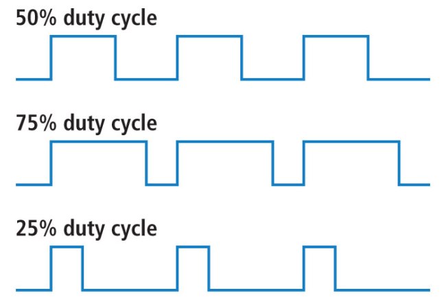
Pulse Width Modulation (PWM)
There are 12x PWM pins available: 2, 3, 4, 5, 6, 7, 11, 12, 13, 14, 17, and 18. Note that these are tied to other peripherals as well.
 |
 |
| PWM Pins Highlighted (Top & Bottom View) |
|
Analog
There are 3x 12-bit analog pins available: A0, A1, and A2.
 |
 |
| ADC Pins Highlighted (Top & Bottom View) |
|
LEDs
There are 4x LEDs populated on the board.
- PWR — The PWR LED lights up to indicate when there is a 3.3V available after power is regulated down from the USB connector or LiPo battery. This can be disabled by cutting the jumper labeled as PWR.
- CHG — The on-board yellow CHG LED can be used to get an indication of the charge status of your battery. Below is a table of other status indicators depending on the state of the charge IC. This can be disabled by cutting the jumper labeled as CHG.
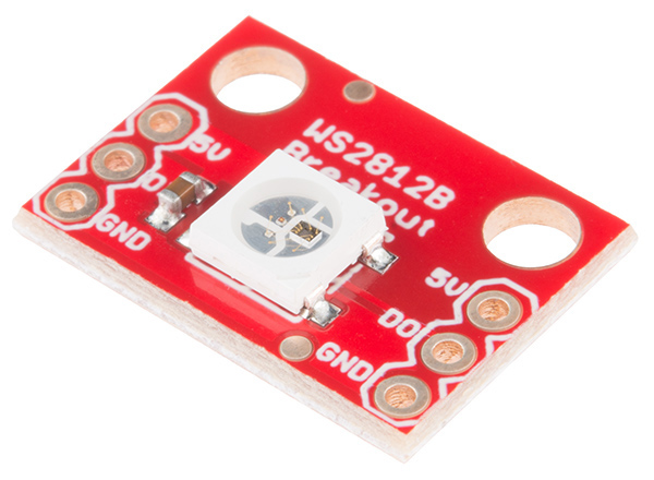
- RGB IO14 — The RGB IO14 LED is an WS2812-2020 LED. Users can control this addressable RGB LED using pin
14. This LED can be disconnected from the pin by cutting the jumper labeled as JP1. For users that are not using this LED and want to conserve power, the 3.3V net can also be disconnected as well by cutting the jumper labeled as JP3. For users that are interested in daisy chaining additional WS2812 LEDs, users can connect to the PTH labled as LD or LED D0. - IO18 — The LED labeled as IO18 can be configured by the user and is connected to pin
18. This can be disconnect from the pin by cutting the jumper labeled JP2.
| Charge State | LED status |
| No Battery | Floating (should be OFF, but may flicker) |
| Shutdown | Floating (should be OFF, but may flicker) |
| Charging | ON |
| Charge Complete | OFF |
 |
 |
| LEDs and Connected PTHs Highlighted (Top & Bottom View) |
|
Jumpers
Note
If this is your first time working with jumpers, check out the How to Work with Jumper Pads and PCB Traces tutorial for more information.
There are a few jumper pads available on the bottom of the board.
- SHLD — This jumper connects the USB Type C connector's shield pin to GND. Cut this to isolate the USB Type C connector's shield pin. This is for advanced users that want to ground their board to their enclosure instead of the ground plane.
- MEAS — To enable measurements and determine how long your battery might last, we've added a NC (normally closed) jumper between the two MEAS PTH pins. By cutting this jumper, the voltage connecting to the 3.3V voltage regulator input is interrupted. Soldering in a male jumper or wires into the accompanying holes will give you the ability to insert a current meter and precisely monitor how much current your application is consuming.
- PWR — By default, this jumper is closed. Cut this trace to disable the power LED that is connected to 3.3V.
- CHG — By default, this jumper is closed. Cut this trace to disable the charge LED that is connected to the LiPo charge IC.
- LED_D0 — By default, this jumper is closed. Cut this trace to disable the WS2812 addressable RGB LED's output pin labeled as
D0. - JP1 — By default, this jumper is closed. Cut this trace to disable the WS2812 addressable RGB LED's input pin that is connected to pin
14. - JP2 — By default, this jumper is closed. Cut this trace to disable the user LED that is connected to pin
18. - JP3 — By default, this jumper is closed. Cut this trace to disable power connected to the WS2812 addressable LED's 3.3V pin.
- CUR — This three way jumper sets the charge IC's charge rate. By default, it's connected to the pad labeled 500 so the charge rate is set to 500mA. Cutting a trace and adding a solder jumper between the center pad and the pad labeled as 100 will set the charge rate to 100mA.
- I2C — By default, this three-pad jumper is closed and located on the bottom of the board. The three way jumper labeled I2C connect the two 2.2kΩ pull-up resistors to the I2C data and clock lines. If multiple devices are connected to the bus with the pull-up resistors enabled, the parallel equivalent resistance will create too strong of a pull-up for the bus to operate correctly. As a general rule of thumb, disable all but one pair of pull-up resistors if multiple devices are connected to the bus.
- SDPC — By default, this jumper is closed and for the microSD card's power control circuit. Cut this trace on the GND/ON side to disable power to the microSD card's socket. For users that want to control the transistor via a GPIO, add a solder blob between the center pad and the pad that is labeled 17. Make sure to also define the pin in code to toggle power to the microSD card.
 |
 |
| Jumpers Highlighted (Top & Bottom View) |
|
Board Dimensions
The board is 0.9" x 2.3" (22.86mm x 58.42mm) and uses the standard Thing+ footprint. There are 4x mounting holes by each corner of the board. You can use 4-40 standoffs to mount the board to a panel or enclosure.
 |
| Board Dimensions |
Hardware Hookup
At a minimum, you will need to plug in the USB C cable to the SparkFun Thing Plus NORA-W306 to power and program the board.
 |
| USB Cable inserted into Thing Plus NORA-W306 |
Single Cell LiPo Battery
Battery Polarity
Please make sure that you use one of our recommended Lithium Ion batteries. Some batteries use the same JST connector as ours but have the opposite polarity. Connecting one of these to your SparkFun Thing Plus NORA-W306 will destroy it. If you are going to use your own battery, it is up to you to ensure it has the correct polarity.
For remote applications, you can connect a standard single cell LiPo battery. The SparkFun Thing Plus NORA-W306 has a built-in charger too which will charge your battery at 500mA when a USB-C is connected. Please make sure your battery capacity is at least 500mAh (0.5Ah); bad things will happen if you try to charge smaller batteries using the board's default charge rate of 500mA. Of course, you can adjust the charge rate with the 3-way jumper on the back of the board. The yellow CHG charging LED will light up while the battery is charging and will turn off once charging is complete.
 |
| Battery Connected |
The MCP73831 charge IC on the board is used on a few SparkFun products. For more information about the CHG status LED, we recommend taking look at the Hardware Overview. We also recommend taking a look at this tutorial for Single Cell LiPo Battery Care.
Inserting a MicroSD Card
For those that need to store data, you can add a microSD card to your application. You will just need to insert a microSD card with the metal contacts facing the board and into the socket on the back. Compared to other microSD cards sockets in sparkFun's storefront, this will not have a click to lock the memory card in place. Just make sure to fully insert the memory card.
 |
| MicroSD Card in Socket |
You should only insert or remove the SD card while the power is turned off or disconnected. Removing the card while the SparkFun Thing Plus NORA-W306 is powered will almost certainly corrupt your data.
Connecting via Qwiic
For users that want to connect a Qwiic-enabled device, you will simply need to insert a cable between the Qwiic connectors. Then insert a USB cable between the microcontroller and your computer to power and program.
 |
| Qwiic-enabled Device Connected to Thing Plus NORA-W306 |
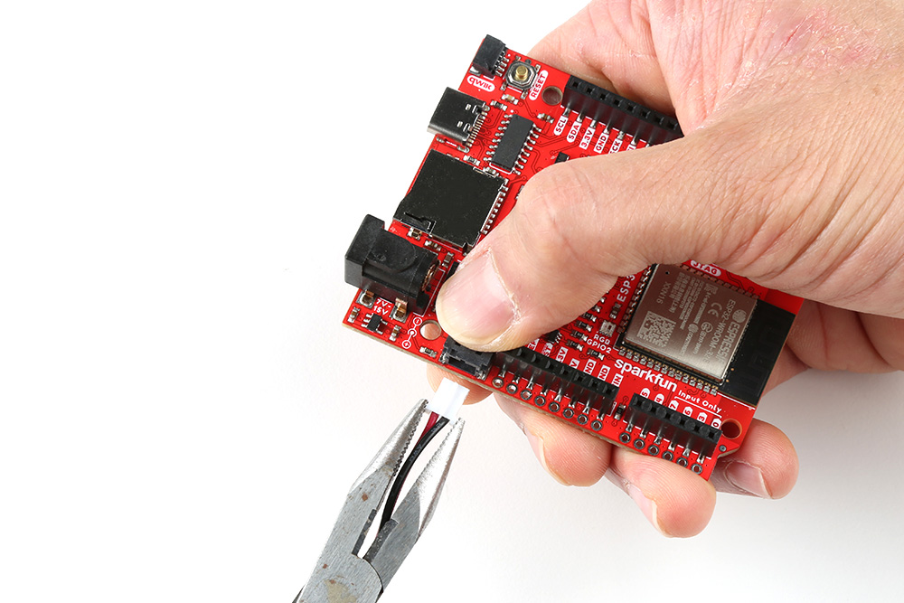
Connecting via PTH
For temporary connections to the PTHs, you could use IC hooks to test out the pins. However, you'll need to solder headers or wires of your choice to the board for a secure connection. You can choose between a combination of header pins and jumper wires, or stripping wire and soldering the wire directly to the board.

Installing the CP2102 USB Driver
Warning
Make sure to manually install the driver for the CP2102N with the following instructions. The driver that Windows auto-installs will not work with the auto-reset circuit on the board and can cause serial uploads to fail.
You will also need to install the SiLabs CP210X Driver, which can be found here: USB to UART Bridge VCP Driver.
Note
If applicable, make sure you are using the proper driver files for your CPU architecture. This is usually indicated by a folder or file name with "x86" for 32-bit processors or "x64" for 64-bit processors.
Setting Up Arduino
Arduino
This example assumes you are using the latest version of the Arduino IDE on your desktop. If this is your first time using Arduino IDE, library, or board add-on, please review the following tutorials.
Install the Realtek Board Add-on
First, open your Arduino preferences (File > Preferences). Then find the Additional Boards Manager URLs text box, and paste the below link in. If you have other links for other 3rd party boards, you will need to add a comma (,) between each link in the field. You can also open an additional window by clicking the window button next to the Additional Boards Manager URLs: field and add the link to a separate line.
https://github.com/ambiot/ambd_arduino/raw/dev/Arduino_package/package_realtek_amebad_early_index.json
 |
| Realtek Arduino Board Support Files for the NORA-W306 |
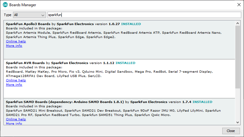
Then hit "OK", and travel back to the Board Manager menu. Type "realtek" in the search bar and hit enter. Click on the "Install" button for the Realtek Ameba Boards (32-bit ARM Cortex-M33 @200MHz) by Realtek. Downloading and installing the tools may take a couple minutes. Feel free to walk around, grab some water, or do a little dance while the tools install.
 |
| Search for realtek in Arduino Boards Manager |
Once installed, the version number and Arduino-blue "INSTALLED" text should appear next to the boards list entry.
 |
| Installed Realtek Arduino Core |
Selecting the SparkFun Thing Plus NORA-306
To upload code to the board, you will need to select the correct board. From the menu, select the following: Tools > Board > Realtek Ameba Boards (32-bits ARM Cortex-M33 @200MHz) > SparkFun Thing Plus NORA-306 (RTL8720DF) .
 |
| Screenshot Board Selection |
There are a few options for the board. One of them is the option to automatically upload code to the board without the need to press the BOOT and RESET buttons as Arduino uploads your code. By default, the Auto Upload Mode is disabled. From the menu, select the following: Tools > Auto Upload Mode: > Enable .
 |
| Screenshot of Auto Upload Mode |
COM Port Selection
You will also need to select the COM port that the board enumerated to. From the menu, select your respective COM port on your computer (in this case, it was COM13 on a Windows computer): Tools > Port > COM___ .
 |
| Screenshot COM Port Selection |
Installing the Arduino Library
To take advantage of a few of the built-in components on the board, you will need to install a Arduino Library. Of course, you may need additional Arduino Libraries depending on what you connect to the development board. At a minimum, you will need the following listed below to take advantage of the built-in LiPo Fuel Gauge (MAX17048).
SparkFun MAX1704x Fuel Gauge Arduino Library
SparkFun has written a library to work with the LiPo Fuel Gauge - MAX17048 that is built into the SparkFun Thing Plus NORA-W306. You can obtain this library through the Arduino Library Manager by searching for "SparkFun MAX1704x Fuel Gauge". Find the one written by SparkFun Electronics and install the latest version. Users who prefer to manually install the library can get it from the GitHub Repository or download the .ZIP by clicking the button below:
SdFat Arduino Library
Bill Greiman has written a library for memory cards formatted to FAT16/FAT32 exFAT. We used this Arduino Library instead of the ones that were listed in the libraries included with the AmebaD. You can obtain this library through the Arduino Library Manager by searching for "sdfat". Find the one written by Bill Greiman and install the latest version. Users who prefer to manually install the library can get it from the GitHub Repository or download the .ZIP by clicking the button below:
Note
At the time of writing, SdFat by Bill Greiman v2.2.3 worked with the SparkFun Thing Plus - NORA-W306.
Note
We recommend using some of the built-in libraries for the u-blox NORA-W306 as well after installing the board add-ons: File > Examples > Examples for SparkFun Thing Plus NORA-W306 (RTL8720DF) . Certain examples like the AmebaWS2812B were written specifically for the NORA-W306 architecture.
 |
| More Arduino Examples! |
Arduino
Example 1 - Blink
Now that we have our board add-on installed, we can get started playing around with the development board. For the scope of this tutorial, we will highlight a few of the features on the board. From there we will be able to build our own custom code to integrate the development board into a project.
In this example, we will blink the LED that is built into the SparkFun Thing Plus NORA-W306.
Hardware Hookup
The connection is the same as explained earlier in the tutorial. Connect the USB cable to the SparkFun Thing Plus NORA-W306. Of course, make sure to connect the other end to your computer.
|
| USB Cable inserted into Thing Plus NORA-W306 |
Arduino Code
Let's upload a sketch to the board. This example is the basic Arduino blink example. Note that we specify pin 18 instead of using the macro called LED_BUILTIN.
Copy and paste the following code in the Arduino IDE. Select the correct board definition from the menu (in this case, Tools > Board > Realtek Ameba Boards (32-bits ARM Cortex-M33 @200MHz) > SparkFun Thing Plus NORA-W306 (RTL8720DF). Then select the correct COM port that the board enumerated to (in this case, it was COM13). Hit upload button.
/*
  Blink
  Turns on an LED on for one second, then off for one second, repeatedly.

  This example code is in the public domain.
 */

// Pin 18 has an LED connected on most Arduino boards.
// give it a name:
int led = 18; //LED is connected to pin 18 on the SparkFun Thing Plus NORA-W306

//NOTE: You can also use LED_BUILTIN.

// the setup routine runs once when you press reset:
void setup() {
  // initialize the digital pin as an output.
  pinMode(led, OUTPUT);
}

// the loop routine runs over and over again forever:
void loop() {
  digitalWrite(led, HIGH);   // turn the LED on (HIGH is the voltage level)
  delay(1000);               // wait for a second
  digitalWrite(led, LOW);    // turn the LED off by making the voltage LOW
  delay(1000);               // wait for a second
}
Note
Note: You can also use the macro for the LED by using LED_BUILTIN. The code in the built-in Arduino examples will function the same as well!
Once uploaded, check the LED labeled as 18 on the board. It should be blinking on and off every second! Sweet!
 |
| SparkFun Thing Plus NORA-W306 User LED On |
Example 2: Button
--8<-- "./docs/arduino_example_2_button.md
Example 3 - Scanning WiFi Networks
In this example, we will scan for WiFi networks in the area.
Hardware Hookup
The connection is the same as explained earlier in the tutorial. Connect the USB cable to the SparkFun Thing Plus NORA-W306. Of course, make sure to connect the other end to your computer. You will also need a wireless router capable of 2.4GHz and 5GHz.
|
| USB Cable inserted into Thing Plus NORA-W306 |
Arduino Code
Let's try to scan for some WiFi networks. You can find this example included after installing the board add-on. Head to File > Examples > Examples for SparkFun Thing Plus NORA-W306 (RTL8720DF) | WiFi > ScanNetworks .
You can also copy and paste the following code in the Arduino IDE. Select the correct board definition from the menu (in this case, Tools > Board > Realtek Ameba Boards (32-bits ARM Cortex-M33 @200MHz) > SparkFun Thing Plus NORA-W306 (RTL8720DF)). Then select the correct COM port that the board enumerated to (in this case, it was COM13). Hit upload button.
/*
 This example prints MAC address, and
 scans for available Wifi networks.
 Every ten seconds, it scans again. It doesn't actually
 connect to any network, so no encryption scheme is specified.

 created 13 July 2010
 by dlf (Metodo2 srl)
 modified 21 Junn 2012
 by Tom Igoe and Jaymes Dec

 modified 08 May 2023
 by Realtek SG

 Example guide:
 https://www.amebaiot.com/en/amebad-arduino-scan-wifi/
 */

#include <WiFi.h>

int status = WL_IDLE_STATUS;    // Indicater of Wifi status

void setup() {
    //Initialize serial and wait for port to open:
    Serial.begin(115200);
    while (!Serial) {
        ; // wait for serial port to connect. Needed for native USB port only
    }

    // check for WiFi status:
    status = WiFi.status();
    // Print WiFi MAC address:
    printMacAddress();
}

void loop() {
    // scan for existing networks:
    Serial.println("Scanning available networks...");
    listNetworks();
    delay(10000);
}

void printMacAddress() {
    // print your MAC address:
    byte mac[6];
    WiFi.macAddress(mac);
    Serial.print("MAC: ");
    Serial.print(mac[0], HEX);
    Serial.print(":");
    Serial.print(mac[1], HEX);
    Serial.print(":");
    Serial.print(mac[2], HEX);
    Serial.print(":");
    Serial.print(mac[3], HEX);
    Serial.print(":");
    Serial.print(mac[4], HEX);
    Serial.print(":");
    Serial.println(mac[5], HEX);
}

void listNetworks() {
    // scan for nearby networks:
    Serial.println("** Scan Networks **");
    int numSsid = WiFi.scanNetworks();
    if (numSsid == -1) {
        Serial.println("Couldn't get a wifi connection");
        while (true);
    }

    // print the list of networks seen:
    Serial.print("number of available networks:");
    Serial.println(numSsid);

    // print the network number and name for each network found:
    for (int thisNet = 0; thisNet < numSsid; thisNet++) {
        Serial.print(thisNet);
        Serial.print(") ");
        Serial.print(WiFi.SSID(thisNet));
        Serial.print("\tSignal: ");
        Serial.print(WiFi.RSSI(thisNet));
        Serial.print(" dBm");
        Serial.print("\tEncryptionRaw: ");
        printEncryptionTypeEx(WiFi.encryptionTypeEx(thisNet));
        Serial.print("\tEncryption: ");
        printEncryptionType(WiFi.encryptionType(thisNet));
    }
}

void printEncryptionTypeEx(uint32_t thisType) {
    /*  Arduino wifi api use encryption type to mapping to security type.
    *  This function demonstrate how to get more richful information of security type.
    */
    switch (thisType) {
        case SECURITY_OPEN:
            Serial.print("Open");
            break;
        case SECURITY_WEP_PSK:
            Serial.print("WEP");
            break;
        case SECURITY_WPA_TKIP_PSK:
            Serial.print("WPA TKIP");
            break;
        case SECURITY_WPA_AES_PSK:
            Serial.print("WPA AES");
            break;
        case SECURITY_WPA2_AES_PSK:
            Serial.print("WPA2 AES");
            break;
        case SECURITY_WPA2_TKIP_PSK:
            Serial.print("WPA2 TKIP");
            break;
        case SECURITY_WPA2_MIXED_PSK:
            Serial.print("WPA2 Mixed");
            break;
        case SECURITY_WPA_WPA2_MIXED:
            Serial.print("WPA/WPA2 AES");
            break;
        case SECURITY_WPA3_AES_PSK:
            Serial.print("WPA3 AES");
            break;
        case SECURITY_WPA2_WPA3_MIXED:
            Serial.print("WPA2/WPA3");
    }
}

void printEncryptionType(int thisType) {
    // read the encryption type and print out the name:
    switch (thisType) {
        case ENC_TYPE_WEP:
            Serial.println("WEP");
            break;
        case ENC_TYPE_WPA:
            Serial.println("WPA");
            break;
        case ENC_TYPE_WPA2:
            Serial.println("WPA2");
            break;
        case ENC_TYPE_WPA3:
            Serial.println("WPA3");
            break;
        case ENC_TYPE_NONE:
            Serial.println("None");
            break;
        case ENC_TYPE_AUTO:
            Serial.println("Auto");
            break;
    }
}
Open you Arduino Serial Monitor at 115200. The SparkFun Thing Plus NORA-W306 will begin scanning your area. Take note of the encryption type of the WiFi network that you are connecting to. In this case, I had set my home WiFi Router's 5GHz network name to "SparkFun_Router_5GHz" and it was using a WPA2 encryption (as highlighted in the Arduino Serial Monitor).
 |
| SparkFun Router 5GHz Highlighted Arduino Output |
Example 4 - Connecting to a WiFi Network
In this example, we will connect to a 5GHz WiFi network.
Hardware Hookup
The connection is the same as explained earlier in the tutorial. Connect the USB cable to the SparkFun Thing Plus NORA-W306 and the other end to your computer. Again, you will need a wireless router capable of 2.4GHz and 5GHz.
|
| USB Cable inserted into Thing Plus NORA-W306 |
Arduino Code
Let's upload the sketch to connect to the 5GHz network in your area. From the menu, select the following: File > Examples > File > Examples > Examples for SparkFun Thing Plus NORA-W306 (RTL8720DF) | WiFi > ConnectWithWiFi > ConnectWithWPA. Depending on your encryption, you may select a different example.
Note
Depending on your encryption, you may select a different Arduino sketch to connect to the WiFi. Based on the previous example, the connection used WPA so we selected the ConnectWithWPA.ino example.
Or you can copy and paste the following code in the Arduino IDE.
/*
 This example connects to an unencrypted Wifi network.
 Then it prints the MAC address,
 the IP address obtained, and other network details.

 created 13 July 2010
 by dlf (Metodo2 srl)
 modified 31 May 2012
 by Tom Igoe

 modified 08 May 2023
 by Realtek SG

 Example guide:
 https://www.amebaiot.com/en/amebad-arduino-connect-wifi/
 */

#include <WiFi.h>

// Set if user wants to key in ssid/pwd manually during operation
//#define MANUAL_INPUT

#ifdef MANUAL_INPUT  // Initialise ssid string, pwd string, and serial_in object
// Initialise strings
String str_ssid, str_pass;
#endif

// If you are connecting to an iPhone WiFi hotspot, the default SSID uses Unicode (U+2019) Right Single Quotation Mark instead of ASCII apostrophe
// Modify the "Your Name" section in the SSID below to connect to an iPhone using a default SSID style
// char ssid[] = "Your Name\xE2\x80\x99s iPhone";

// UTF-8 encoding can also be used for SSID with emoji characters
// Emoji characters can be converted into UTF-8 at https://mothereff.in/utf-8
// char ssid[] = "\xe2\x9c\x8c\xef\xb8\x8f Ameba \xe2\x9c\x8c\xef\xb8\x8f";

char ssid[] = "Network_SSID";       // your network SSID (name)
char pass[] = "Password";           // your network password
int status = WL_IDLE_STATUS;        // Indicater of Wifi status

void setup() {
    //Initialize serial and wait for port to open:
    Serial.begin(115200);
    while (!Serial) {
        ; // wait for serial port to connect. Needed for native USB port only
    }

    // attempt to connect to Wifi network:
    while (status != WL_CONNECTED) {
#ifdef MANUAL_INPUT
        Serial.println("Enter your ssid");
        while (Serial.available() == 0) {}
            str_ssid = Serial.readString();
            str_ssid.trim();
            Serial.print("SSID entered: ");
            Serial.println(str_ssid);

        Serial.println("Enter your password");
        while (Serial.available() == 0) {}
        str_pass = Serial.readString();
        str_pass.trim();
            if (str_pass.length() != 0) { // user has entered data
                while (str_pass.length() <8 ) { // to catch pwd<8 exception
                    Serial.println("Password cannot be less than 8 characters! Try again");
                    while (Serial.available() == 0) {}
                    str_pass = Serial.readString();
                    str_pass.trim();
                }
                    Serial.print("Password entered: ");
                    Serial.println(str_pass);
            }
#endif
        Serial.print("Attempting to connect to WPA SSID: ");

#ifndef MANUAL_INPUT
        Serial.println(ssid);
        // Connect to WPA/WPA2 network:
        status = WiFi.begin(ssid, pass);
#else
        char ssid_cust[str_ssid.length() + 1];
        char pass_cust[str_pass.length() + 1];
        strcpy(ssid_cust, str_ssid.c_str());
        strcpy(pass_cust, str_pass.c_str());
        Serial.println(str_ssid.c_str());
        status = WiFi.begin(ssid_cust, pass_cust);
        str_ssid = str_pass = "";
#endif
        // wait 10 seconds for connection:
        delay(10000);
    }

    // you're connected now, so print out the data:
    Serial.println();
    Serial.print("You're connected to the network");
    printCurrentNet();
    printWifiData();
}

void loop() {
    // check the network connection once every 10 seconds:
    delay(10000);
    printCurrentNet();
}

void printWifiData() {
    // print your WiFi IP address:
    IPAddress ip = WiFi.localIP();
    Serial.print("IP Address: ");
    Serial.println(ip);
    Serial.println(ip);

    // print your MAC address:
    byte mac[6];
    WiFi.macAddress(mac);
    Serial.print("MAC address: ");
    Serial.print(mac[0], HEX);
    Serial.print(":");
    Serial.print(mac[1], HEX);
    Serial.print(":");
    Serial.print(mac[2], HEX);
    Serial.print(":");
    Serial.print(mac[3], HEX);
    Serial.print(":");
    Serial.print(mac[4], HEX);
    Serial.print(":");
    Serial.println(mac[5], HEX);
}

void printCurrentNet() {
    // print the SSID of the network you're attached to:
    Serial.print("SSID: ");
    Serial.println(WiFi.SSID());

    // print the MAC address of the router you're attached to:
    byte bssid[6];
    WiFi.BSSID(bssid);
    Serial.print("BSSID: ");
    Serial.print(bssid[5], HEX);
    Serial.print(":");
    Serial.print(bssid[4], HEX);
    Serial.print(":");
    Serial.print(bssid[3], HEX);
    Serial.print(":");
    Serial.print(bssid[2], HEX);
    Serial.print(":");
    Serial.print(bssid[1], HEX);
    Serial.print(":");
    Serial.println(bssid[0], HEX);

    // print the received signal strength:
    long rssi = WiFi.RSSI();
    Serial.print("signal strength (RSSI):");
    Serial.println(rssi);

    // print the encryption type:
    byte encryption = WiFi.encryptionType();
    Serial.print("Encryption Type:");
    Serial.println(encryption, HEX);
    Serial.println();
}
Then adjust the arrays that holed the SSID (i.e. yourNetwork) and password (secretPassword) based on your WiFi network's settings.
 |
| SSID Changed |
Select the correct board definition from the menu (in this case, Tools > Boards > SparkFun Thing Plus NORA-W306 (RTL8720DF)). Then select the correct COM port that the board enumerated to (in this case, it was COM13). Hit upload button.
Open the Arduino Serial Monitor at 115200. The SparkFun Thing Plus NORA-W306 will attempt to connect to the network.
 |
| Serial Monitor attempting to connect to WiFi network |
If all goes well, you should see some status outputs and message indicating that you are connected to your network! In this case, I had the following message:
You're connected to the networkSSID: SparkFun_Router_5GHz
The serial output will then continue outputting the status of the connection some of which include the SSID, signal strength (RSSI), and encryption type. If you have admin privileges, you can check to see if the device is connected to the 5GHz WiFi network as well. Try connecting to a website and pulling the local time or weather in your area!
Example 5a - Bluetooth UART Service
In the following two examples, we will connect two NORA-W306 development boards via Bluetooth and send serial characters.
Hardware Hookup
Connect the USB C cables to the boards and two different COM ports on your computer.
Tip
To keep track of which board that you are connecting to, use a sticky note and label the boards that you are using as the Service and Client.
|
| USB Cable inserted into Thing Plus NORA-W306 |
When connecting and disconnecting the boards from your computer, you will noticed that the COM port enumerates to a certain number from the menu Tools > Port. Feel free to write down the COM port on the sticky note as well after uploading code.
Arduino Code
Let's upload the sketch to send serial data between two SparkFun Thing Plus NORA-W306 boards wirelessly using the Bluetooth® Low Energy (BLE) feature. From the menu, select the following: File > Examples > File > Examples > Examples for SparkFun Thing Plus NORA-W306 (RTL8720DF) | AmebaBLE > BLEUartService.
Or you can copy and paste the following code in the Arduino IDE. Select the correct board definition from the menu (in this case, Tools > Boards > SparkFun Thing Plus NORA-W306 (RTL8720DF)). Then select the correct COM port that the board enumerated to (in this case, it was COM13). Hit upload button.
/*

 Example guide:
 https://www.amebaiot.com/en/amebad-arduino-ble-uart-service/
 */

#include "BLEDevice.h"

#define UART_SERVICE_UUID      "6E400001-B5A3-F393-E0A9-E50E24DCCA9E"
#define CHARACTERISTIC_UUID_RX "6E400002-B5A3-F393-E0A9-E50E24DCCA9E"
#define CHARACTERISTIC_UUID_TX "6E400003-B5A3-F393-E0A9-E50E24DCCA9E"

#define STRING_BUF_SIZE 100

BLEService UartService(UART_SERVICE_UUID);
BLECharacteristic Rx(CHARACTERISTIC_UUID_RX);
BLECharacteristic Tx(CHARACTERISTIC_UUID_TX);
BLEAdvertData advdata;
BLEAdvertData scndata;
bool notify = false;

void readCB (BLECharacteristic* chr, uint8_t connID) {
    Serial.print("Characteristic ");
    Serial.print(chr->getUUID().str());
    Serial.print(" read by connection ");
    Serial.println(connID);
}

void writeCB (BLECharacteristic* chr, uint8_t connID) {
    Serial.print("Characteristic ");
    Serial.print(chr->getUUID().str());
    Serial.print(" write by connection ");
    Serial.println(connID);
    if (chr->getDataLen() > 0) {
        Serial.print("Received string: ");
        Serial.print(chr->readString());
        Serial.println();
    }
}

void notifCB(BLECharacteristic* chr, uint8_t connID, uint16_t cccd) {
    if (cccd & GATT_CLIENT_CHAR_CONFIG_NOTIFY) {
        //printf("Notifications enabled on Characteristic %s for connection %d \n", chr->getUUID().str(), connID);
        Serial.print("Notifications enabled on Characteristic");
        notify = true;
    } else {
        //printf("Notifications disabled on Characteristic %s for connection %d \n", chr->getUUID().str(), connID);
        Serial.print("Notifications disabled on Characteristic");
        notify = false;
    }
    Serial.print(chr->getUUID().str());
    Serial.print(" for connection");
    Serial.println(connID);
}

void setup() {
    Serial.begin(115200);

    advdata.addFlags(GAP_ADTYPE_FLAGS_LIMITED | GAP_ADTYPE_FLAGS_BREDR_NOT_SUPPORTED);
    advdata.addCompleteName("AMEBA_BLE_DEV");
    scndata.addCompleteServices(BLEUUID(UART_SERVICE_UUID));

    Rx.setWriteProperty(true);
    Rx.setWritePermissions(GATT_PERM_WRITE);
    Rx.setWriteCallback(writeCB);
    Rx.setBufferLen(STRING_BUF_SIZE);
    Tx.setReadProperty(true);
    Tx.setReadPermissions(GATT_PERM_READ);
    Tx.setReadCallback(readCB);
    Tx.setNotifyProperty(true);
    Tx.setCCCDCallback(notifCB);
    Tx.setBufferLen(STRING_BUF_SIZE);

    UartService.addCharacteristic(Rx);
    UartService.addCharacteristic(Tx);

    BLE.init();
    BLE.configAdvert()->setAdvData(advdata);
    BLE.configAdvert()->setScanRspData(scndata);
    BLE.configServer(1);
    BLE.addService(UartService);

    BLE.beginPeripheral();
}

void loop() {
    if (Serial.available()) {
        Tx.writeString(Serial.readString());
        if (BLE.connected(0) && notify) {
            Tx.notify(0);
        }
    }
    delay(100);
}
When finished uploading, head to the next section to upload code to a second SparkFun Thing Plus NORA-W306 board.
Example 5b - Bluetooth UART Client
We will upload code for the Bluetooth UART client in this example. Then we will send characters between two serial terminals.
Hardware Hookup
Connect the USB C cables to the boards and two different COM ports on your computer.
Tip
To keep track of which board that you are connecting to, use a sticky note and label the boards that you are using as the Service and Client.
|
| USB Cable inserted into Thing Plus NORA-W306 |
Arduino Code
Let's upload the corresponding sketch to send serial data between two SparkFun Thing Plus NORA-W306 boards wirelessly using the Bluetooth® Low Energy (BLE) feature. From the menu, select the following: File > Examples > File > Examples > Examples for SparkFun Thing Plus NORA-W306 (RTL8720DF) | AmebaBLE > BLEUartClient.
Or you can copy and paste the following code in the Arduino IDE. Select the correct board definition from the menu (in this case, Tools > Boards > SparkFun Thing Plus NORA-W306 (RTL8720DF)). Then select the correct COM port that the board enumerated to (in this case, it was COM22). Hit upload button.
/*

 Example guide:
 https://www.amebaiot.com/en/amebad-arduino-ble-uart/
 */

#include "BLEDevice.h"

#define UART_SERVICE_UUID      "6E400001-B5A3-F393-E0A9-E50E24DCCA9E"
#define CHARACTERISTIC_UUID_RX "6E400002-B5A3-F393-E0A9-E50E24DCCA9E"
#define CHARACTERISTIC_UUID_TX "6E400003-B5A3-F393-E0A9-E50E24DCCA9E"

#define STRING_BUF_SIZE 100

BLEAdvertData foundDevice;
BLEAdvertData targetDevice;
BLEClient* client;
BLERemoteService* UartService;
BLERemoteCharacteristic* Rx;
BLERemoteCharacteristic* Tx;

void scanCB(T_LE_CB_DATA* p_data) {
    foundDevice.parseScanInfo(p_data);
    if (foundDevice.hasName()) {
        if (foundDevice.getName() == String("AMEBA_BLE_DEV")) {
            Serial.print("Found Ameba BLE Device at address ");
            Serial.println(foundDevice.getAddr().str());
            targetDevice = foundDevice;
        }
    }
}

void notificationCB (BLERemoteCharacteristic* chr, uint8_t* data, uint16_t len) {
    char msg[len+1] = {0};
    memcpy(msg, data, len);
    Serial.print("Notification received for chr UUID: ");
    Serial.println(chr->getUUID().str());
    Serial.print("Received string: ");
    Serial.println(String(msg));
}

void setup() {
    Serial.begin(115200);

    BLE.init();
    BLE.setScanCallback(scanCB);
    BLE.beginCentral(1);

    BLE.configScan()->startScan(2000);
    BLE.configConnection()->connect(targetDevice, 2000);
    delay(2000);
    int8_t connID = BLE.configConnection()->getConnId(targetDevice);
    if (!BLE.connected(connID)) {
        Serial.println("BLE not connected");
    } else {
        BLE.configClient();
        client = BLE.addClient(connID);
        client->discoverServices();
        Serial.print("Discovering services of connected device");
        do {
            Serial.print(".");
            delay(1000);
        } while (!(client->discoveryDone()));
        Serial.println();

        UartService = client->getService(UART_SERVICE_UUID);
        if (UartService != nullptr) {
            Tx = UartService->getCharacteristic(CHARACTERISTIC_UUID_TX);
            if (Tx != nullptr) {
                Serial.println("TX characteristic found");
                Tx->setBufferLen(STRING_BUF_SIZE);
                Tx->setNotifyCallback(notificationCB);
                Tx->enableNotifyIndicate();
            }
            Rx = UartService->getCharacteristic(CHARACTERISTIC_UUID_RX);
            if (Rx != nullptr) {
                Serial.println("RX characteristic found");
                Rx->setBufferLen(STRING_BUF_SIZE);
            }
        }
    }
}

void loop() {
    if (Serial.available()) {
        Rx->writeString(Serial.readString());
    }
    delay(100);
}
To test, open the Arduino Serial Monitor for the client device on its respective COM port at 115200. Then open a second serial terminal (in this case we used TeraTerm) for the previous service device on its respective COM port at 115200. Type some characters and hit Send button from the client device. You should see the same characters received on the service device! Then try typing messages from the service to the client. Again, you should see the same characters on the other end. You may need to turn on the local echo depending on the terminal window that you are using.
 |
 |
| BLE UART Service via Tera Term | BLE UART Client via Arduino Serial Monitor |
Example 6 - MicroSD Card
In this example, we will write some text to a microSD card and read the contents of the text file for verification.
Hardware Hookup
Make sure to insert a microSD card into the microSD card socket on the back of the board.
|
| MicroSD Card in Socket |
When ready, connect the board to your computer with the USB C cable.
Arduino Library
If you have not already, make sure to install the following library as explained earlier. Keep in mind there is more than one SdFat Arduino Library. We recommend using the SdFat Arduino Library by Bill Greiman.
Arduino Code
Let's check your microSD card, write some text to a fill, and read hte contents of the file for verification
Copy and paste the following code in the Arduino IDE. Select the correct board definition from the menu (in this case, Tools > Boards > SparkFun Thing Plus NORA-W306 (RTL8720DF)). Then select the correct COM port that the board enumerated to (in this case, it was COM13). Hit upload button.
/*
SparkFun Electronics
7/17/2024


SD card example for the SparkFun Thing Plus NORA-W306


Note, the SparkFun Thing Plus NORA-W306 does not use the SDIO hardware peripheral.
It utilizes SPI0 to communicate with the uSD card.


Using sdFAT and the onboard uSD socket (SPI0), this program attempts to:

  1. Initialize an SD card and analyze its structure.


  2. Create a file on the SD card and write a string to it.


  3. Open the file and print the contents to the serial monitor.


Hardware Hookup and Instructions:
  Insert an SD card into the SD card slot on the NORA-W306.
  Connect the NORA-W306 to your computer using a USB-C cable.
  Upload this code to the NORA-W306.
  Open the serial monitor to see the results.


Software versions used in this example:
  Arduino IDE 2.3.2
  usdFAT by Bill Greiman, Arduino Library Version 2.2.3
    (https://github.com/greiman/SdFat)
  Realtek Ameba Boards (32-bits ARM Cortex-M33 @200MHz) by Realtek Version 3.1.8
    (https://github.com/ambiot/ambd_arduino)
    (https://raw.githubusercontent.com/ambiot/ambd_arduino/dev/Arduino_package/package_realtek_amebad_early_index.json)


Original code is from the following two examples in the SdFat library:
  SdInfo - Program to read and display SD card information
    -MIT License, Copyright (c) 2011..2020 Bill Greiman
  examplesV1/ReadWrite - Program to test read and write functions
    -Public Domain, created Nov 2010 by David A. Mellis, modified 9 Apr 2012 by Tom Igoe


MIT License


Copyright (c) 2024 SparkFun Electronics


Permission is hereby granted, free of charge, to any person obtaining a copy of
this software and associated documentation files (the "Software"), to deal in the
Software without restriction, including without limitation the rights to use,
copy, modify, merge, publish, distribute, sublicense, and/or sell copies of the
Software, and to permit persons to whom the Software is furnished to do so,
subject to the following conditions:


The above copyright notice and this permission notice shall be included in all
copies or substantial portions of the Software.


THE SOFTWARE IS PROVIDED "AS IS", WITHOUT WARRANTY OF ANY KIND, EXPRESS OR IMPLIED,
INCLUDING BUT NOT LIMITED TO THE WARRANTIES OF MERCHANTABILITY, FITNESS FOR A
PARTICULAR PURPOSE AND NONINFRINGEMENT. IN NO EVENT SHALL THE AUTHORS OR COPYRIGHT
HOLDERS BE LIABLE FOR ANY CLAIM, DAMAGES OR OTHER LIABILITY, WHETHER IN AN ACTION
OF CONTRACT, TORT OR OTHERWISE, ARISING FROM, OUT OF OR IN CONNECTION WITH THE
SOFTWARE OR THE USE OR OTHER DEALINGS IN THE SOFTWARE.
*/


#include "SdFat.h"
#include "sdios.h"


File myFile;


/*
  Set DISABLE_CS_PIN to disable a second SPI device.
  For example, with the Ethernet shield, set DISABLE_CS_PIN
  to 10 to disable the Ethernet controller.
*/
const int8_t DISABLE_CS_PIN = -1;
/*
  Change the value of SD_CS_PIN if you are using SPI
  and your hardware does not use the default value, SS.
  Common values are:
  Arduino Ethernet shield: pin 4
  Sparkfun SD shield: pin 8
  Adafruit SD shields and modules: pin 10
  SparkFun Thing Plus NORA-W306: Arduino pin 4 (aka SS/PB_21/SPI0_CS)
*/
// SDCARD_SS_PIN is defined for the built-in SD on some boards.
#ifndef SDCARD_SS_PIN
const uint8_t SD_CS_PIN = SS;
#else   // SDCARD_SS_PIN
const uint8_t SD_CS_PIN = SDCARD_SS_PIN;
#endif  // SDCARD_SS_PIN


// Try to select the best SD card configuration.
#if HAS_SDIO_CLASS
#define SD_CONFIG SdioConfig(FIFO_SDIO)
#elif ENABLE_DEDICATED_SPI
#define SD_CONFIG SdSpiConfig(SD_CS_PIN, DEDICATED_SPI, SD_SCK_MHZ(16))
#else  // HAS_SDIO_CLASS
#define SD_CONFIG SdSpiConfig(SD_CS_PIN, SHARED_SPI, SD_SCK_MHZ(16))
#endif  // HAS_SDIO_CLASS


//------------------------------------------------------------------------------
SdFs sd;
cid_t cid;
csd_t csd;
scr_t scr;
uint8_t cmd6Data[64];
uint32_t eraseSize;
uint32_t ocr;
static ArduinoOutStream cout(Serial);
//------------------------------------------------------------------------------
void cidDmp() {
  cout << F("\nManufacturer ID: ");
  cout << uppercase << showbase << hex << int(cid.mid) << dec << endl;
  cout << F("OEM ID: ") << cid.oid[0] << cid.oid[1] << endl;
  cout << F("Product: ");
  for (uint8_t i = 0; i < 5; i++) {
    cout << cid.pnm[i];
  }
  cout << F("\nRevision: ") << cid.prvN() << '.' << cid.prvM() << endl;
  cout << F("Serial number: ") << hex << cid.psn() << dec << endl;
  cout << F("Manufacturing date: ");
  cout << cid.mdtMonth() << '/' << cid.mdtYear() << endl;
  cout << endl;
}
//------------------------------------------------------------------------------
void clearSerialInput() {
  uint32_t m = micros();
  do {
    if (Serial.read() >= 0) {
      m = micros();
    }
  } while (micros() - m < 10000);
}
//------------------------------------------------------------------------------
void csdDmp() {
  eraseSize = csd.eraseSize();
  cout << F("cardSize: ") << 0.000512 * csd.capacity();
  cout << F(" MB (MB = 1,000,000 bytes)\n");


  cout << F("flashEraseSize: ") << int(eraseSize) << F(" blocks\n");
  cout << F("eraseSingleBlock: ");
  if (csd.eraseSingleBlock()) {
    cout << F("true\n");
  } else {
    cout << F("false\n");
  }
  cout << F("dataAfterErase: ");
  if (scr.dataAfterErase()) {
    cout << F("ones\n");
  } else {
    cout << F("zeros\n");
  }
}
//------------------------------------------------------------------------------
void errorPrint() {
  if (sd.sdErrorCode()) {
    cout << F("SD errorCode: ") << hex << showbase;
    printSdErrorSymbol(&Serial, sd.sdErrorCode());
    cout << F(" = ") << int(sd.sdErrorCode()) << endl;
    cout << F("SD errorData = ") << int(sd.sdErrorData()) << dec << endl;
  }
}
//------------------------------------------------------------------------------
bool mbrDmp() {
  MbrSector_t mbr;
  bool valid = true;
  if (!sd.card()->readSector(0, (uint8_t *)&mbr)) {
    cout << F("\nread MBR failed.\n");
    errorPrint();
    return false;
  }
  cout << F("\nSD Partition Table\n");
  cout << F("part,boot,bgnCHS[3],type,endCHS[3],start,length\n");
  for (uint8_t ip = 1; ip < 5; ip++) {
    MbrPart_t *pt = &mbr.part[ip - 1];
    if ((pt->boot != 0 && pt->boot != 0X80) || getLe32(pt->relativeSectors) > csd.capacity()) {
      valid = false;
    }
    cout << int(ip) << ',' << uppercase << showbase << hex;
    cout << int(pt->boot) << ',';
    for (int i = 0; i < 3; i++) {
      cout << int(pt->beginCHS[i]) << ',';
    }
    cout << int(pt->type) << ',';
    for (int i = 0; i < 3; i++) {
      cout << int(pt->endCHS[i]) << ',';
    }
    cout << dec << getLe32(pt->relativeSectors) << ',';
    cout << getLe32(pt->totalSectors) << endl;
  }
  if (!valid) {
    cout << F("\nMBR not valid, assuming Super Floppy format.\n");
  }
  return true;
}
//------------------------------------------------------------------------------
void dmpVol() {
  cout << F("\nScanning FAT, please wait.\n");
  int32_t freeClusterCount = sd.freeClusterCount();
  if (sd.fatType() <= 32) {
    cout << F("\nVolume is FAT") << int(sd.fatType()) << endl;
  } else {
    cout << F("\nVolume is exFAT\n");
  }
  cout << F("sectorsPerCluster: ") << sd.sectorsPerCluster() << endl;
  cout << F("fatStartSector:    ") << sd.fatStartSector() << endl;
  cout << F("dataStartSector:   ") << sd.dataStartSector() << endl;
  cout << F("clusterCount:      ") << sd.clusterCount() << endl;
  cout << F("freeClusterCount:  ");
  if (freeClusterCount >= 0) {
    cout << freeClusterCount << endl;
  } else {
    cout << F("failed\n");
    errorPrint();
  }
}
//------------------------------------------------------------------------------
void printCardType() {
  cout << F("\nCard type: ");
  switch (sd.card()->type()) {
    case SD_CARD_TYPE_SD1:
      cout << F("SD1\n");
      break;
    case SD_CARD_TYPE_SD2:
      cout << F("SD2\n");
      break;
    case SD_CARD_TYPE_SDHC:
      if (csd.capacity() < 70000000) {
        cout << F("SDHC\n");
      } else {
        cout << F("SDXC\n");
      }
      break;
    default:
      cout << F("Unknown\n");
  }
}
//------------------------------------------------------------------------------
void printConfig(SdSpiConfig config) {
  if (DISABLE_CS_PIN < 0) {
    cout << F(
      "\nAssuming the SD is the only SPI device.\n"
      "Edit DISABLE_CS_PIN to disable an SPI device.\n");
  } else {
    cout << F("\nDisabling SPI device on pin ");
    cout << int(DISABLE_CS_PIN) << endl;
    pinMode(DISABLE_CS_PIN, OUTPUT);
    digitalWrite(DISABLE_CS_PIN, HIGH);
  }
  cout << F("\nAssuming the SD chip select pin is: ") << int(config.csPin);
  cout << F("\nEdit SD_CS_PIN to change the SD chip select pin.\n");
}
//------------------------------------------------------------------------------
void printConfig(SdioConfig config) {
  (void)config;
  cout << F("Assuming an SDIO interface.\n");
}
//-----------------------------------------------------------------------------
void setup() {
  Serial.begin(9600);
  // Wait for USB Serial
  while (!Serial) {
    yield();
  }
  cout << F("SdFat version: ") << SD_FAT_VERSION_STR << endl;
  printConfig(SD_CONFIG);
}
//------------------------------------------------------------------------------
void loop() {
  // Read any existing Serial data.
  clearSerialInput();


  // F stores strings in flash to save RAM
  cout << F("\ntype any character to start\n");
  while (!Serial.available()) {
    yield();
  }
  uint32_t t = millis();
  if (!sd.cardBegin(SD_CONFIG)) {
    cout << F(
      "\nSD initialization failed.\n"
      "Do not reformat the card!\n"
      "Is the card correctly inserted?\n"
      "Is there a wiring/soldering problem?\n");
    if (isSpi(SD_CONFIG)) {
      cout << F(
        "Is SD_CS_PIN set to the correct value?\n"
        "Does another SPI device need to be disabled?\n");
    }
    errorPrint();
    return;
  }
  t = millis() - t;
  cout << F("init time: ") << dec << t << " ms" << endl;


  if (!sd.card()->readCID(&cid) || !sd.card()->readCSD(&csd) || !sd.card()->readOCR(&ocr) || !sd.card()->readSCR(&scr)) {
    cout << F("readInfo failed\n");
    errorPrint();
    return;
  }
  printCardType();
  cout << F("sdSpecVer: ") << 0.01 * scr.sdSpecVer() << endl;
  cout << F("HighSpeedMode: ");
  if (scr.sdSpecVer() && sd.card()->cardCMD6(0X00FFFFFF, cmd6Data) && (2 & cmd6Data[13])) {
    cout << F("true\n");
  } else {
    cout << F("false\n");
  }
  cidDmp();
  csdDmp();
  cout << F("\nOCR: ") << uppercase << showbase;
  cout << hex << ocr << dec << endl;
  if (!mbrDmp()) {
    return;
  }
  if (!sd.volumeBegin()) {
    cout << F("\nvolumeBegin failed. Is the card formatted?\n");
    errorPrint();
    return;
  }
  dmpVol();
  test();
}
//------------------------------------------------------------------------------
void test() {
  // open the file. note that only one file can be open at a time,
  // so you have to close this one before opening another.
  myFile = sd.open("test.txt", FILE_WRITE);


  // if the file opened okay, write to it:
  if (myFile) {
    Serial.print("Writing to test.txt...");
    myFile.println("testing 3,4,5 wahoo");
    // close the file:
    myFile.close();
    Serial.println("done.");
  } else {
    // if the file didn't open, print an error:
    Serial.println("error opening test.txt");
  }


  // re-open the file for reading:
  myFile = sd.open("test.txt");
  if (myFile) {
    Serial.println("test.txt:");


    // read from the file until there's nothing else in it:
    while (myFile.available()) {
      Serial.write(myFile.read());
    }
    // close the file:
    myFile.close();
  } else {
    // if the file didn't open, print an error:
    Serial.println("error opening test.txt");
  }
}
Open the Arduino Serial Monitor at 115200 baud. Send a character through the Arduino Serial Monitor. You should get a prompt in the Serial Monitor. Enter a chararacter (i.e. send s or any other keyboard character) to start. The example will then read the card. If the card is compatible, the output will provide information about the microSD card type, create a new file, write text to the file, and then close the file. The example will then re-open the file and read the contents of the file. You should see the following text in the file: "testing 3,4,5 wahoo". If the example code is run more than once, you may see the same text repeat a few times.
 |
| MicroSD Card Test Output |
To open using the a file explorer, you can disconnect the SparkFun Thing Plus - NORA-W306, remove the microSD card, and connect it to a computer with a microSD card adapter. Once connected, you can open the test.txt file with a text editor to verify the text written in the file.
 |
| File Explorer Text Editor Verification |
Example 7 - Deep Sleep and Blink
In this example, we will show how to set your board in deep sleep, blink the user LED as an indicator, and then go back into power saving mode.
Note
This is a modified example from the Realtek's Arduino example for Deep Sleep Mode.
Hardware Hookup
For users interested in measuring the current draw via the MEAS jumper, you can cut the trace located on the back of the board. Power the board via USB or battery. Then place a multimeter set to measure current on the PTHs. This makes it easier to measure the current as opposed to measuring the current between the power source and connector.
Note
The MEAS jumper is before the XC6222 3.3V voltage regulator. For users that are connecting power to the 3V3 pin or Qwiic connector, you will need to place a multimeter between the regulated 3.3V power source and the board.
 |
| MEAS Jumper Modified |
To upload code, connect the USB cable to the SparkFun Thing Plus NORA-W306. Of course, make sure to connect the other end to your computer.
|
| USB Cable inserted into Thing Plus NORA-W306 |
Tip
Make sure to add a solder blob on the MEAS jumper when finished measuring. Users can also solder a 2-pin male header and shunt to the PTHs to easily remove/add the connection.
Arduino Code
This example builds upon Realtek's deep sleep mode. Once the deep sleep modes are set up, the NORA-W306 goes into deep sleep. In this particular example, we will use the timer (i.e. SET_DS_AON_TIMER_WAKEUP) as the source. After 5 seconds, the board wakes up with the user LED also blinking five times before going back to deep sleep for 5 seconds.
Note
The serial UART is disabled to reduce amount the peripherals that are turned on. To save more power, you can cut the JP3 and PWR LED jumpers. There is also a fancy circuit to disable power to the CP2102 when there is no USB power. As an alternative to USB power, users can power the board with a LiPo battery.
Copy and paste the following code in the Arduino IDE. Select your Board (in this case the SparkFun Thing Plus NORA-W306 (RTL8720DF)), and associated COM port (in this case COM13). Then hit the upload button.
/*
* SparkFun Electronics
* 7/17/2024
*
* SparkFun_ThingPlus_NORAW306_DeepSleepBlink.ino
*
* Deep Sleep mode example for the SparkFun Thing Plus NORA-W306
*
* This example demonstrates how to put the NORA-W306 into deep sleep mode and
* wake it up using the AON timer (every 5 seconds).
* When awake, the onboard LED will blink.
* When asleep, the current consumption can be monitored using the MEAS jumper.
*
* Hardware Hookup and Instructions:
*   Connect the NORA-W306 to your computer using a USB-C cable.
*   Upload this code to the NORA-W306.
*   To measure the low-power consumption of the NORA-W306, remove USB-C cable
*   and utilize the MEAS jumper to measure the current consumption.
*
* Software versions used in this example:
*   Arduino IDE 2.3.2
*   Realtek Ameba Boards (32-bits ARM Cortex-M33 @200MHz) by Realtek Version 3.1.8
*     (https://github.com/ambiot/ambd_arduino)
*     (https://raw.githubusercontent.com/ambiot/ambd_arduino/dev/Arduino_package/package_realtek_amebad_early_index.json)
*
* Original code is from the following example in the RealTek Ameba Arduino package:
*  Examples -> AmebaPowerSave -> DeepSleepMode.ino
*
* MIT License
*
* Copyright (c) 2024 SparkFun Electronics
*
* Permission is hereby granted, free of charge, to any person obtaining a copy of
* this software and associated documentation files (the "Software"), to deal in the
* Software without restriction, including without limitation the rights to use,
* copy, modify, merge, publish, distribute, sublicense, and/or sell copies of the
* Software, and to permit persons to whom the Software is furnished to do so,
* subject to the following conditions:
*
* The above copyright notice and this permission notice shall be included in all
* copies or substantial portions of the Software.
*
* THE SOFTWARE IS PROVIDED "AS IS", WITHOUT WARRANTY OF ANY KIND, EXPRESS OR IMPLIED,
* INCLUDING BUT NOT LIMITED TO THE WARRANTIES OF MERCHANTABILITY, FITNESS FOR A
* PARTICULAR PURPOSE AND NONINFRINGEMENT. IN NO EVENT SHALL THE AUTHORS OR COPYRIGHT
* HOLDERS BE LIABLE FOR ANY CLAIM, DAMAGES OR OTHER LIABILITY, WHETHER IN AN ACTION
* OF CONTRACT, TORT OR OTHERWISE, ARISING FROM, OUT OF OR IN CONNECTION WITH THE
* SOFTWARE OR THE USE OR OTHER DEALINGS IN THE SOFTWARE.
*/

#include <PowerSave.h>

//SET_DS_AON_TIMER_WAKEUP
//SET_DS_RTC_WAKEUP
//For AMB21/22 only the AON GPIO pins listed below should be selected
    //SET_AON_GPIO_WAKEUP_PA25          // pin 16
    //SET_AON_GPIO_WAKEUP_PA26          // pin 17
    //SET_AON_GPIO_WAKEUP_PA21          // pin 26
    //SET_AON_GPIO_WAKEUP_PA20          // pin 27
    //SET_AON_GPIO_WAKEUP_PA19          // pin 28
//For AMB23 only the AON GPIO pins listed below should be selected
    //SET_AON_GPIO_WAKEUP_PA12          // pin 9
    //SET_AON_GPIO_WAKEUP_PA13          // pin 10
    //SET_AON_GPIO_WAKEUP_PA14          // pin 11
    //SET_AON_GPIO_WAKEUP_PA15          // pin 12
    //SET_AON_GPIO_WAKEUP_PA16          // pin 13
    //SET_AON_GPIO_WAKEUP_PA18          // pin 15
    //SET_AON_GPIO_WAKEUP_PA19          // pin 16
    //SET_AON_GPIO_WAKEUP_PA21          // pin 18
//For BW16/BW16-TypeC only the AON GPIO pins listed below should be selected
    //SET_AON_GPIO_WAKEUP_PA25          // pin 7
    //SET_AON_GPIO_WAKEUP_PA26          // pin 8
    //SET_AON_GPIO_WAKEUP_PA15          // pin 9
    //SET_AON_GPIO_WAKEUP_PA14          // pin 10
    //SET_AON_GPIO_WAKEUP_PA13          // pin 11
    //SET_AON_GPIO_WAKEUP_PA12          // pin 12
//For board AW-CU488_ThingPlus
    //SET_AON_GPIO_WAKEUP_PA18          // pin 0
    //SET_AON_GPIO_WAKEUP_PA16          // pin 1
    //SET_AON_GPIO_WAKEUP_PA17          // pin 2
    //SET_AON_GPIO_WAKEUP_PA13          // pin 3
    //SET_AON_GPIO_WAKEUP_PA12          // pin 4
    //SET_AON_GPIO_WAKEUP_PA26          // pin 5
    //SET_AON_GPIO_WAKEUP_PA25          // pin 6
    //SET_AON_GPIO_WAKEUP_PA19          // pin 8
    //SET_AON_GPIO_WAKEUP_PA15          // pin 28
    //SET_AON_GPIO_WAKEUP_PA14          // pin 29
//For board AMB25/AMB26
    //SET_AON_GPIO_WAKEUP_PA12          // pin 3
    //SET_AON_GPIO_WAKEUP_PA13          // pin 2
    //SET_AON_GPIO_WAKEUP_PA14          // pin 1
    //SET_AON_GPIO_WAKEUP_PA15          // pin 0
    //SET_AON_GPIO_WAKEUP_PA25          // pin 7
    //SET_AON_GPIO_WAKEUP_PA26          // pin 6
//For board SparkFun Thing Plus NORA-W306
    //SET_AON_GPIO_WAKEUP_PA18          // pin 6
    //SET_AON_GPIO_WAKEUP_PA13          // pin 13
    //SET_AON_GPIO_WAKEUP_PA12          // pin 14
    //SET_AON_GPIO_WAKEUP_PA26          // pin 11
    //SET_AON_GPIO_WAKEUP_PA25          // pin 12
    //SET_AON_GPIO_WAKEUP_PA15          // pin 15
    //SET_AON_GPIO_WAKEUP_PA14          // pin 16

#define DS_WAKEUP_SOURCE                SET_DS_AON_TIMER_WAKEUP

#define AON_TIMER_SLEEP_DURATION        5000
#define DS_RTC_ALARM_DAY                0
#define DS_RTC_ALARM_HOUR               0
#define DS_RTC_ALARM_MIN                0
#define DS_RTC_ALARM_SEC                10

void DeepSleep_wakeup(void) {
    //printf("\r\nDeep sleep wakeuped! \r\n");
    uint32_t wakereason_number = PowerSave.AONWakeReason();

    //pinMode(17, OUTPUT); // 17 SDPC uSD power control
    //digitalWrite(17, LOW); // Turn on uSD power if you'd like to measure its current consumption

    if (wakereason_number == AONWakeReason_AON_GPIO) {
        //printf("AonWakepin wakeup. Wait 5s sleep again.    \r\n");
        delay(5000);
    } else if (wakereason_number == AONWakeReason_AON_TIMER) {
        PowerSave.AONTimerCmd();
        //printf("AonTimer wakeup. Wait 5s sleep again.    \r\n");

        pinMode(LED_BUILTIN, OUTPUT);
        for(int i = 0 ; i < 5 ; i ++)
        {
          digitalWrite(LED_BUILTIN, HIGH);
          delay(1000);
          digitalWrite(LED_BUILTIN, LOW);
          delay(1000);
        }
        pinMode(LED_BUILTIN, INPUT);
        //delay(5000);
    } else if (wakereason_number == AONWakeReason_RTC) {
        //printf("RTC wakeup. Wait 5s sleep again.    \r\n");
        delay(5000);
    }

    //pinMode(17, INPUT_PULLUP); // 17 SDPC uSD power control (Pullup = off)

    PowerSave.AONWakeClear();
}

void setup() {
    // If you want serial debug messages, uncomment the following lines and others
    // below, as desired.
    // Open serial communications and wait for port to open:
    // Serial.begin(115200);
    // while (!Serial) {
    //     ; // wait for serial port to connect. Needed for native USB port only
    // }

    // Pin configuration - specific to the SparkFun Thing Plus NORA-W306

    pinMode(0, INPUT_PULLDOWN); // LOG RX, can backpower the CP2102
    pinMode(1, INPUT_PULLDOWN); // LOG TX, can backpower the CP2102
    pinMode(4, INPUT_PULLDOWN); // SPI0_CS, can sink current from 3V3 via R16 (100K), note, this is only possible if you leave uSD power on
    pinMode(5, INPUT_PULLDOWN); // SPI0_CLK
    pinMode(6, INPUT_PULLDOWN); // SPI0_PICO
    pinMode(7, INPUT_PULLDOWN); // SPI0_POCI

    pinMode(11, INPUT_PULLUP); // SDA
    pinMode(12, INPUT_PULLUP); // SCL
    pinMode(17, INPUT_PULLUP); // 17 SDPC uSD power control
    pinMode(20, INPUT_PULLNONE); // aka PB_24, this is tied internally to PB_23 (aka Arduino pin "17") and also defaults to internal pulldown.

    PowerSave.begin(DEEPSLEEP_MODE);

    if (TRUE == (PowerSave.DsleepWakeStatusGet())) {
        DeepSleep_wakeup();
    }

    PowerSave.AONTimerDuration(0);

    switch (DS_WAKEUP_SOURCE) {
        case SET_DS_AON_TIMER_WAKEUP:
            PowerSave.DS_AON_TIMER_WAKEUP();
            PowerSave.AONTimerDuration(AON_TIMER_SLEEP_DURATION);
            break;
        case SET_DS_RTC_WAKEUP:
            PowerSave.DS_RTC_WAKEUP();
            PowerSave.RTCWakeSetup(DS_RTC_ALARM_DAY, DS_RTC_ALARM_HOUR, DS_RTC_ALARM_MIN, DS_RTC_ALARM_SEC);
            break;
        case SET_AON_GPIO_WAKEUP_PA12:
            PowerSave.AON_WAKEPIN_WAKEUP_PA12();
            break;
        case SET_AON_GPIO_WAKEUP_PA13:
            PowerSave.AON_WAKEPIN_WAKEUP_PA13();
            break;
        case SET_AON_GPIO_WAKEUP_PA14:
            PowerSave.AON_WAKEPIN_WAKEUP_PA14();
            break;
        case SET_AON_GPIO_WAKEUP_PA15:
            PowerSave.AON_WAKEPIN_WAKEUP_PA15();
            break;
        case SET_AON_GPIO_WAKEUP_PA16:
            PowerSave.AON_WAKEPIN_WAKEUP_PA16();
            break;
        case SET_AON_GPIO_WAKEUP_PA17:
            PowerSave.AON_WAKEPIN_WAKEUP_PA17();
            break;
        case SET_AON_GPIO_WAKEUP_PA18:
            PowerSave.AON_WAKEPIN_WAKEUP_PA18();
            break;
        case SET_AON_GPIO_WAKEUP_PA19:
            PowerSave.AON_WAKEPIN_WAKEUP_PA19();
            break;
        case SET_AON_GPIO_WAKEUP_PA20:
            PowerSave.AON_WAKEPIN_WAKEUP_PA20();
            break;
        case SET_AON_GPIO_WAKEUP_PA21:
            PowerSave.AON_WAKEPIN_WAKEUP_PA21();
            break;
        case SET_AON_GPIO_WAKEUP_PA25:
            PowerSave.AON_WAKEPIN_WAKEUP_PA25();
            break;
        case SET_AON_GPIO_WAKEUP_PA26:
            PowerSave.AON_WAKEPIN_WAKEUP_PA26();
            break;
        default:
            printf("Unknown wakeup source.    \r\n");
        break;
    }

    PowerSave.enable();
}

void loop() {
    delay(1000);
}
Once connected, choose a power source to connect to the SparkFun Thing Plus NORA-W306. This can be through the PTHs on the edge of the board (VU, VB, or 3V3) or the connectors (USB C, 2-pin JST, or Qwiic). Note that the board will draw more power through the USB C connector and VU PTH as this will power the CP2102. Power will also be drawn with the LiPo charger and 3.3V voltage regulator.
Below are a few diagrams showing two possible ways to measure the current draw when the board is in deep sleep mode.
 |
 |
| Fritzing Diagram of Multimeter Measuring Current through MEAS and a LiPo Battery as the Power Source | Fritzing Diagram of Multimeter Measuring Current LiPo Battery and Board |
If you haven't already, check out the demo video that was linked earlier in the hardware overview showing the current draw for the board in low power mode!
Example 8 - Deep Sleep and MicroSD Power Control
In this example, we will read sensor readings from a BME280, log the data to a microSD card, and then go into deep sleep.
Hardware Hookup
To take advantage of the SD power control (SDPC), you will need to make sure to cut the trace on the back of the board and add a solder blob between the center pad and pad labeled as 17.
 |
| MicroSD Card Power Control Jumper Modified |
When ready, insert a microSD card into the socket on the back of the board. Then connect the Qwiic BME280 to the SparkFun Thing Plus NORA-W306 using a Qwiic cable.
 |
| Fritzing Diagram BME280 connected to NORA-W306 via Qwiic |
Connect a USB cable to the board to power and upload code.
Arduino Code
This example builds upon Realtek's deep sleep like the previous example. In addition to blinking the LED, we will also read the temperature from a BME280 and write the sensor data to the microSD card.
Copy and paste the following code in the Arduino IDE. Select your Board (in this case the SparkFun Thing Plus NORA-W306 (RTL8720DF)), and associated COM port (in this case COM23). Then hit the upload button.
/*
* SparkFun Electronics
* 7/17/2024
*
* SparkFun_ThingPlus_NORAW306_DeepSleepTempLogger.ino
*
* Deep Sleep mode with data logging  - example for the SparkFun Thing Plus NORA-W306
*
* This example demonstrates how to put the NORA-W306 into deep sleep mode and
* wake it up using the AON timer (every 5 seconds).
* When awake, it will log the temperature from the BME280 sensor to the uSD card.
* When awake, it will also blink the stat LED three times to indicate a log has happened.
* When asleep, the current consumption can be monitored using the MEAS jumper.
*
* Hardware Hookup and Instructions:
*   Connect the NORA-W306 to your computer using a USB-C cable.
*   Connect the BME280 sensor with a Qwiic Cable.
*   Upload this code to the NORA-W306.
*   To measure the low-power consumption of the NORA-W306, remove USB-C cable
*   and utilize the MEAS jumper to measure the current consumption.
*
* Software versions used in this example:
*   Arduino IDE 2.3.2
*   Realtek Ameba Boards (32-bits ARM Cortex-M33 @200MHz) by Realtek Version 3.1.8
*     (https://github.com/ambiot/ambd_arduino)
*     (https://raw.githubusercontent.com/ambiot/ambd_arduino/dev/Arduino_package/package_realtek_amebad_early_index.json)
*   BME280 library by SparkFun Electronics
*     (https://github.com/sparkfun/SparkFun_BME280_Arduino_Library)
*
* Original code is from the following example in the RealTek Ameba Arduino package:
*  Examples -> AmebaPowerSave -> DeepSleepMode.ino
*
* MIT License
*
* Copyright (c) 2024 SparkFun Electronics
*
* Permission is hereby granted, free of charge, to any person obtaining a copy of
* this software and associated documentation files (the "Software"), to deal in the
* Software without restriction, including without limitation the rights to use,
* copy, modify, merge, publish, distribute, sublicense, and/or sell copies of the
* Software, and to permit persons to whom the Software is furnished to do so,
* subject to the following conditions:
*
* The above copyright notice and this permission notice shall be included in all
* copies or substantial portions of the Software.
*
* THE SOFTWARE IS PROVIDED "AS IS", WITHOUT WARRANTY OF ANY KIND, EXPRESS OR IMPLIED,
* INCLUDING BUT NOT LIMITED TO THE WARRANTIES OF MERCHANTABILITY, FITNESS FOR A
* PARTICULAR PURPOSE AND NONINFRINGEMENT. IN NO EVENT SHALL THE AUTHORS OR COPYRIGHT
* HOLDERS BE LIABLE FOR ANY CLAIM, DAMAGES OR OTHER LIABILITY, WHETHER IN AN ACTION
* OF CONTRACT, TORT OR OTHERWISE, ARISING FROM, OUT OF OR IN CONNECTION WITH THE
* SOFTWARE OR THE USE OR OTHER DEALINGS IN THE SOFTWARE.
*/

// variables to store the readings from the sensor
float humidity;
float pressure;
float altitude;
float temperature;

#include "SdFat.h"
#include "sdios.h"

File myFile;

/*
  Set DISABLE_CS_PIN to disable a second SPI device.
  For example, with the Ethernet shield, set DISABLE_CS_PIN
  to 10 to disable the Ethernet controller.
*/
const int8_t DISABLE_CS_PIN = -1;
/*
  Change the value of SD_CS_PIN if you are using SPI
  and your hardware does not use the default value, SS.
  Common values are:
  Arduino Ethernet shield: pin 4
  Sparkfun SD shield: pin 8
  Adafruit SD shields and modules: pin 10
  SparkFun Thing Plus NORA-W306: Arduino pin 4 (aka SS/PB_21/SPI0_CS)
*/
// SDCARD_SS_PIN is defined for the built-in SD on some boards.
#ifndef SDCARD_SS_PIN
const uint8_t SD_CS_PIN = SS;
#else  // SDCARD_SS_PIN
const uint8_t SD_CS_PIN = SDCARD_SS_PIN;
#endif  // SDCARD_SS_PIN

// Try to select the best SD card configuration.
#if HAS_SDIO_CLASS
#define SD_CONFIG SdioConfig(FIFO_SDIO)
#elif ENABLE_DEDICATED_SPI
#define SD_CONFIG SdSpiConfig(SD_CS_PIN, DEDICATED_SPI, SD_SCK_MHZ(16))
#else  // HAS_SDIO_CLASS
#define SD_CONFIG SdSpiConfig(SD_CS_PIN, SHARED_SPI, SD_SCK_MHZ(16))
#endif  // HAS_SDIO_CLASS

//------------------------------------------------------------------------------
SdFs sd;
cid_t cid;
csd_t csd;
scr_t scr;
uint8_t cmd6Data[64];
uint32_t eraseSize;
uint32_t ocr;
static ArduinoOutStream cout(Serial);


#include <Wire.h>

#include "SparkFunBME280.h"
BME280 mySensor;

#include <PowerSave.h>

//SET_DS_AON_TIMER_WAKEUP
//SET_DS_RTC_WAKEUP
//For AMB21/22 only the AON GPIO pins listed below should be selected
    //SET_AON_GPIO_WAKEUP_PA25          // pin 16
    //SET_AON_GPIO_WAKEUP_PA26          // pin 17
    //SET_AON_GPIO_WAKEUP_PA21          // pin 26
    //SET_AON_GPIO_WAKEUP_PA20          // pin 27
    //SET_AON_GPIO_WAKEUP_PA19          // pin 28
//For AMB23 only the AON GPIO pins listed below should be selected
    //SET_AON_GPIO_WAKEUP_PA12          // pin 9
    //SET_AON_GPIO_WAKEUP_PA13          // pin 10
    //SET_AON_GPIO_WAKEUP_PA14          // pin 11
    //SET_AON_GPIO_WAKEUP_PA15          // pin 12
    //SET_AON_GPIO_WAKEUP_PA16          // pin 13
    //SET_AON_GPIO_WAKEUP_PA18          // pin 15
    //SET_AON_GPIO_WAKEUP_PA19          // pin 16
    //SET_AON_GPIO_WAKEUP_PA21          // pin 18
//For BW16/BW16-TypeC only the AON GPIO pins listed below should be selected
    //SET_AON_GPIO_WAKEUP_PA25          // pin 7
    //SET_AON_GPIO_WAKEUP_PA26          // pin 8
    //SET_AON_GPIO_WAKEUP_PA15          // pin 9
    //SET_AON_GPIO_WAKEUP_PA14          // pin 10
    //SET_AON_GPIO_WAKEUP_PA13          // pin 11
    //SET_AON_GPIO_WAKEUP_PA12          // pin 12
//For board AW-CU488_ThingPlus
    //SET_AON_GPIO_WAKEUP_PA18          // pin 0
    //SET_AON_GPIO_WAKEUP_PA16          // pin 1
    //SET_AON_GPIO_WAKEUP_PA17          // pin 2
    //SET_AON_GPIO_WAKEUP_PA13          // pin 3
    //SET_AON_GPIO_WAKEUP_PA12          // pin 4
    //SET_AON_GPIO_WAKEUP_PA26          // pin 5
    //SET_AON_GPIO_WAKEUP_PA25          // pin 6
    //SET_AON_GPIO_WAKEUP_PA19          // pin 8
    //SET_AON_GPIO_WAKEUP_PA15          // pin 28
    //SET_AON_GPIO_WAKEUP_PA14          // pin 29
//For board AMB25/AMB26
    //SET_AON_GPIO_WAKEUP_PA12          // pin 3
    //SET_AON_GPIO_WAKEUP_PA13          // pin 2
    //SET_AON_GPIO_WAKEUP_PA14          // pin 1
    //SET_AON_GPIO_WAKEUP_PA15          // pin 0
    //SET_AON_GPIO_WAKEUP_PA25          // pin 7
    //SET_AON_GPIO_WAKEUP_PA26          // pin 6
//For board SparkFun Thing Plus NORA-W306
    //SET_AON_GPIO_WAKEUP_PA18          // pin 6
    //SET_AON_GPIO_WAKEUP_PA13          // pin 13
    //SET_AON_GPIO_WAKEUP_PA12          // pin 14
    //SET_AON_GPIO_WAKEUP_PA26          // pin 11
    //SET_AON_GPIO_WAKEUP_PA25          // pin 12
    //SET_AON_GPIO_WAKEUP_PA15          // pin 15
    //SET_AON_GPIO_WAKEUP_PA14          // pin 16

#define DS_WAKEUP_SOURCE                SET_DS_AON_TIMER_WAKEUP

#define AON_TIMER_SLEEP_DURATION        5000
#define DS_RTC_ALARM_DAY                0
#define DS_RTC_ALARM_HOUR               0
#define DS_RTC_ALARM_MIN                0
#define DS_RTC_ALARM_SEC                10

void DeepSleep_wakeup(void) {
    //printf("\r\nDeep sleep wakeuped! \r\n");
    uint32_t wakereason_number = PowerSave.AONWakeReason();

    readSensor();

    if (wakereason_number == AONWakeReason_AON_GPIO) {
        //printf("AonWakepin wakeup. Wait 5s sleep again.    \r\n");
        delay(5000);
    } else if (wakereason_number == AONWakeReason_AON_TIMER) {
        PowerSave.AONTimerCmd();
        //printf("AonTimer wakeup. Wait 5s sleep again.    \r\n");

        pinMode(LED_BUILTIN, OUTPUT);
        for(int i = 0 ; i < 3 ; i ++)
        {
          digitalWrite(LED_BUILTIN, HIGH);
          delay(100);
          digitalWrite(LED_BUILTIN, LOW);
          delay(100);
        }
        pinMode(LED_BUILTIN, INPUT);
        //delay(5000);
    } else if (wakereason_number == AONWakeReason_RTC) {

        printf("RTC wakeup. Wait 5s sleep again.    \r\n");

        delay(5000);
    }

    pinMode(0, INPUT_PULLDOWN); // LOG RX, can backpower the CP2102
    pinMode(1, INPUT_PULLDOWN); // LOG TX, can backpower the CP2102
    pinMode(4, INPUT_PULLDOWN); // SPI0_CS, can sink current from 3V3 via R16 (100K), note, this is only possible if you leave uSD power on
    pinMode(5, INPUT_PULLDOWN); // SPI0_CLK
    pinMode(6, INPUT_PULLDOWN); // SPI0_PICO
    pinMode(7, INPUT_PULLDOWN); // SPI0_POCI
    pinMode(11, INPUT_PULLUP); // SDA
    pinMode(12, INPUT_PULLUP); // SCL
    pinMode(17, INPUT_PULLUP); // 17 SDPC uSD power control
    pinMode(20, INPUT_PULLNONE); // aka PB_24, this is tied internally to PB_23 (aka Arduino pin "17") and also defaults to internal pulldown.

    PowerSave.AONWakeClear();
}

void setup() {
    // If you want serial debug messages, uncomment the following lines and others
    // below, as desired.
    // Open serial communications and wait for port to open:
    // Serial.begin(115200);
    // while (!Serial) {
    //     ; // wait for serial port to connect. Needed for native USB port only
    // }

    PowerSave.begin(DEEPSLEEP_MODE);

    if (TRUE == (PowerSave.DsleepWakeStatusGet())) {
        DeepSleep_wakeup();
    }

    PowerSave.AONTimerDuration(0);

    switch (DS_WAKEUP_SOURCE) {
        case SET_DS_AON_TIMER_WAKEUP:
            PowerSave.DS_AON_TIMER_WAKEUP();
            PowerSave.AONTimerDuration(AON_TIMER_SLEEP_DURATION);
            break;
        case SET_DS_RTC_WAKEUP:
            PowerSave.DS_RTC_WAKEUP();
            PowerSave.RTCWakeSetup(DS_RTC_ALARM_DAY, DS_RTC_ALARM_HOUR, DS_RTC_ALARM_MIN, DS_RTC_ALARM_SEC);
            break;
        case SET_AON_GPIO_WAKEUP_PA12:
            PowerSave.AON_WAKEPIN_WAKEUP_PA12();
            break;
        case SET_AON_GPIO_WAKEUP_PA13:
            PowerSave.AON_WAKEPIN_WAKEUP_PA13();
            break;
        case SET_AON_GPIO_WAKEUP_PA14:
            PowerSave.AON_WAKEPIN_WAKEUP_PA14();
            break;
        case SET_AON_GPIO_WAKEUP_PA15:
            PowerSave.AON_WAKEPIN_WAKEUP_PA15();
            break;
        case SET_AON_GPIO_WAKEUP_PA16:
            PowerSave.AON_WAKEPIN_WAKEUP_PA16();
            break;
        case SET_AON_GPIO_WAKEUP_PA17:
            PowerSave.AON_WAKEPIN_WAKEUP_PA17();
            break;
        case SET_AON_GPIO_WAKEUP_PA18:
            PowerSave.AON_WAKEPIN_WAKEUP_PA18();
            break;
        case SET_AON_GPIO_WAKEUP_PA19:
            PowerSave.AON_WAKEPIN_WAKEUP_PA19();
            break;
        case SET_AON_GPIO_WAKEUP_PA20:
            PowerSave.AON_WAKEPIN_WAKEUP_PA20();
            break;
        case SET_AON_GPIO_WAKEUP_PA21:
            PowerSave.AON_WAKEPIN_WAKEUP_PA21();
            break;
        case SET_AON_GPIO_WAKEUP_PA25:
            PowerSave.AON_WAKEPIN_WAKEUP_PA25();
            break;
        case SET_AON_GPIO_WAKEUP_PA26:
            PowerSave.AON_WAKEPIN_WAKEUP_PA26();
            break;
        default:
            printf("Unknown wakeup source.    \r\n");
        break;
    }

    PowerSave.enable();
}

void loop() {
    delay(1000);
}

void readSensor()
{
    pinMode(0, INPUT); // LOG RX, can backpower the CP2102
    pinMode(1, OUTPUT); // LOG TX, can backpower the CP2102

    pinMode(11, OUTPUT); // SDA
    pinMode(12, OUTPUT); // SCL

    pinMode(17, OUTPUT); // 17 SDPC uSD power control
    digitalWrite(17, LOW); // uSD power GND = ON

    Serial.begin(115200);

    cout << F("SdFat version: ") << SD_FAT_VERSION_STR << endl;
    printConfig(SD_CONFIG);
uint32_t t = millis();
      if (!sd.cardBegin(SD_CONFIG)) {
    cout << F(
           "\nSD initialization failed.\n"
           "Do not reformat the card!\n"
           "Is the card correctly inserted?\n"
           "Is there a wiring/soldering problem?\n");
    if (isSpi(SD_CONFIG)) {
      cout << F(
           "Is SD_CS_PIN set to the correct value?\n"
           "Does another SPI device need to be disabled?\n"
           );
    }
    errorPrint();
    return;
  }

    t = millis() - t;
  cout << F("init time: ") << dec << t << " ms" << endl;

  if (!sd.card()->readCID(&cid) ||
      !sd.card()->readCSD(&csd) ||
      !sd.card()->readOCR(&ocr) ||
      !sd.card()->readSCR(&scr)) {
    cout << F("readInfo failed\n");
    errorPrint();
    return;
  }
  printCardType();
  cout << F("sdSpecVer: ") << 0.01*scr.sdSpecVer() << endl;
  cout << F("HighSpeedMode: ");
  if (scr.sdSpecVer() &&
    sd.card()->cardCMD6(0X00FFFFFF, cmd6Data) && (2 & cmd6Data[13])) {
    cout << F("true\n");
  } else {
    cout << F("false\n");
  }
  cidDmp();
  csdDmp();
  cout << F("\nOCR: ") << uppercase << showbase;
  cout << hex << ocr << dec << endl;
  if (!mbrDmp()) {
    return;
  }
  if (!sd.volumeBegin()) {
    cout << F("\nvolumeBegin failed. Is the card formatted?\n");
    errorPrint();
    return;
  }
  dmpVol();


    Wire.begin();
    Wire.setClock(400000); //Increase to fast I2C speed!
    if (mySensor.beginI2C() == false) //Begin communication over I2C
    {
        printf("The sensor did not respond. Please check wiring.");
        while(1); //Freeze
    }

    mySensor.setMode(MODE_FORCED); //Wake up sensor and take reading

    while(mySensor.isMeasuring() == false) ; //Wait for sensor to start measurment
    while(mySensor.isMeasuring() == true) ; //Hang out while sensor completes the reading

    humidity = mySensor.readFloatHumidity();
    pressure = mySensor.readFloatPressure();
    altitude = mySensor.readFloatAltitudeFeet();
    temperature = mySensor.readTempF();

    printf(" Humidity: ");
    printf("%d", int(humidity));

    printf(" Pressure: ");
    printf("%d", int(pressure));

    printf(" Altitude: ");
    printf("%d", int(altitude));

    printf(" Temperature: ");
    printf("%d", int(temperature));

    mySensor.setMode(MODE_SLEEP); //Sleep for now

    Wire.end();

    logDataToSd();
}

//------------------------------------------------------------------------------
void cidDmp() {
  cout << F("\nManufacturer ID: ");
  cout << uppercase << showbase << hex << int(cid.mid) << dec << endl;
  cout << F("OEM ID: ") << cid.oid[0] << cid.oid[1] << endl;
  cout << F("Product: ");
  for (uint8_t i = 0; i < 5; i++) {
    cout << cid.pnm[i];
  }
  cout << F("\nRevision: ") << cid.prvN() << '.' << cid.prvM() << endl;
  cout << F("Serial number: ") << hex << cid.psn() << dec << endl;
  cout << F("Manufacturing date: ");
  cout << cid.mdtMonth() << '/' << cid.mdtYear() << endl;
  cout << endl;
}
//------------------------------------------------------------------------------
void clearSerialInput() {
  uint32_t m = micros();
  do {
    if (Serial.read() >= 0) {
      m = micros();
    }
  } while (micros() - m < 10000);
}
//------------------------------------------------------------------------------
void csdDmp() {
  eraseSize = csd.eraseSize();
  cout << F("cardSize: ") << 0.000512 * csd.capacity();
  cout << F(" MB (MB = 1,000,000 bytes)\n");


  cout << F("flashEraseSize: ") << int(eraseSize) << F(" blocks\n");
  cout << F("eraseSingleBlock: ");
  if (csd.eraseSingleBlock()) {
    cout << F("true\n");
  } else {
    cout << F("false\n");
  }
  cout << F("dataAfterErase: ");
  if (scr.dataAfterErase()) {
    cout << F("ones\n");
  } else {
    cout << F("zeros\n");
  }
}
//------------------------------------------------------------------------------
void errorPrint() {
  if (sd.sdErrorCode()) {
    cout << F("SD errorCode: ") << hex << showbase;
    printSdErrorSymbol(&Serial, sd.sdErrorCode());
    cout << F(" = ") << int(sd.sdErrorCode()) << endl;
    cout << F("SD errorData = ") << int(sd.sdErrorData()) << dec << endl;
  }
}
//------------------------------------------------------------------------------
bool mbrDmp() {
  MbrSector_t mbr;
  bool valid = true;
  if (!sd.card()->readSector(0, (uint8_t*)&mbr)) {
    cout << F("\nread MBR failed.\n");
    errorPrint();
    return false;
  }
  cout << F("\nSD Partition Table\n");
  cout << F("part,boot,bgnCHS[3],type,endCHS[3],start,length\n");
  for (uint8_t ip = 1; ip < 5; ip++) {
    MbrPart_t *pt = &mbr.part[ip - 1];
    if ((pt->boot != 0 && pt->boot != 0X80) ||
        getLe32(pt->relativeSectors) > csd.capacity()) {
      valid = false;
    }
    cout << int(ip) << ',' << uppercase << showbase << hex;
    cout << int(pt->boot) << ',';
    for (int i = 0; i < 3; i++ ) {
      cout << int(pt->beginCHS[i]) << ',';
    }
    cout << int(pt->type) << ',';
    for (int i = 0; i < 3; i++ ) {
      cout << int(pt->endCHS[i]) << ',';
    }
    cout << dec << getLe32(pt->relativeSectors) << ',';
    cout << getLe32(pt->totalSectors) << endl;
  }
  if (!valid) {
    cout << F("\nMBR not valid, assuming Super Floppy format.\n");
  }
  return true;
}
//------------------------------------------------------------------------------
void dmpVol() {
  cout << F("\nScanning FAT, please wait.\n");
  int32_t freeClusterCount = sd.freeClusterCount();
  if (sd.fatType() <= 32) {
    cout << F("\nVolume is FAT") << int(sd.fatType()) << endl;
  } else {
    cout << F("\nVolume is exFAT\n");
  }
  cout << F("sectorsPerCluster: ") << sd.sectorsPerCluster() << endl;
  cout << F("fatStartSector:    ") << sd.fatStartSector() << endl;
  cout << F("dataStartSector:   ") << sd.dataStartSector() << endl;
  cout << F("clusterCount:      ") << sd.clusterCount() << endl;
  cout << F("freeClusterCount:  ");
  if (freeClusterCount >= 0) {
    cout << freeClusterCount << endl;
  } else {
    cout << F("failed\n");
    errorPrint();
  }
}
//------------------------------------------------------------------------------
void printCardType() {
  cout << F("\nCard type: ");
  switch (sd.card()->type()) {
    case SD_CARD_TYPE_SD1:
      cout << F("SD1\n");
      break;
    case SD_CARD_TYPE_SD2:
      cout << F("SD2\n");
      break;
    case SD_CARD_TYPE_SDHC:
      if (csd.capacity() < 70000000) {
        cout << F("SDHC\n");
      } else {
        cout << F("SDXC\n");
      }
      break;
    default:
      cout << F("Unknown\n");
  }
}
//------------------------------------------------------------------------------
void printConfig(SdSpiConfig config) {
  if (DISABLE_CS_PIN < 0) {
    cout << F(
           "\nAssuming the SD is the only SPI device.\n"
           "Edit DISABLE_CS_PIN to disable an SPI device.\n");
  } else {
    cout << F("\nDisabling SPI device on pin ");
    cout << int(DISABLE_CS_PIN) << endl;
    pinMode(DISABLE_CS_PIN, OUTPUT);
    digitalWrite(DISABLE_CS_PIN, HIGH);
  }
  cout << F("\nAssuming the SD chip select pin is: ") << int(config.csPin);
  cout << F("\nEdit SD_CS_PIN to change the SD chip select pin.\n");
}
//------------------------------------------------------------------------------
void printConfig(SdioConfig config) {
  (void)config;
  cout << F("Assuming an SDIO interface.\n");
}

//------------------------------------------------------------------------------
void logDataToSd()
{
  // open the file. note that only one file can be open at a time,
  // so you have to close this one before opening another.
  myFile = sd.open("log.txt", FILE_WRITE);

  // if the file opened okay, write to it:
  if (myFile) {
    Serial.print("Writing to log.txt...");

    myFile.print("Humidity:");
    myFile.print(humidity);
    myFile.print(",Pressure:");
    myFile.print(pressure);
    myFile.print(",Altitude:");
    myFile.print(altitude);
    myFile.print(",Temperature:");
    myFile.println(temperature);

    // close the file:
    myFile.close();
    Serial.println("done.");
  } else {
    // if the file didn't open, print an error:
    Serial.println("error opening log.txt");
  }

  // re-open the file for reading:
  myFile = sd.open("log.txt");
  if (myFile) {
    Serial.println("log.txt:");


    // read from the file until there's nothing else in it:
    while (myFile.available()) {
      Serial.write(myFile.read());
    }
    // close the file:
    myFile.close();
  } else {
    // if the file didn't open, print an error:
    Serial.println("error opening log.txt");
  }
}
Open the Arduino Serial Monitor at 115200 to view the output. You should see the NORA-W306 wake up, read the sensor data, user LED blink, print the data as an integer through the serial terminal, write to a file, and then close the file. For verification, the code will also re-open the file, print the contents of the file, and then close the file again. This is a good time to verify if the sensor readings are being written at the end of the file.
 |
| Arduino Output from the NORA-W306's Deep Sleep and Datalogging Example |
Tip
For users that need to comment out the lines of code to re-open the file and read the sensor data, you will just need to add a multiline comment (i.e. /* and */) around the following lines of code as shown below.
  // re-open the file for reading:
  /*myFile = sd.open("log.txt");
  if (myFile) {
    Serial.println("log.txt:");


    // read from the file until there's nothing else in it:
    while (myFile.available()) {
      Serial.write(myFile.read());
    }
    // close the file:
    myFile.close();
  } else {
    // if the file didn't open, print an error:
    Serial.println("error opening log.txt");
  }*/
Note
The sensor output in the Arduino Serial Monitor displayed the sensor reading as integers. When writing to the file, the sensor readings were floats.
For those that want to verify through a text editor, remove the USB cable from the NORA-W306. Then remove the microSD card from the board. Connect the microSD card to your computer. Using a text editor, open the file labeled as log.txt. You should see the sensor readings that were logged earlier. You may have an additional line of comma separated values written to the file before removing power from the board.
 |
| Log File Opened Through Text Editor Displaying Sensor Readings |
For those interested in viewing the current consumption, cut the MEAS jumper on the back of the NORA-W306. Solder a 1x2 breakaway male header to the board. Then connect it to a multimeter to measure the current consumption. Using a LiPo battery will bring down the current consumption since the LiPo battery charger, CHG LED, and CP2102 USB-to-serial converter are not being powered. Try disabling the power LED jumpers on the NORA-W306 and BME280. You can take it a step further by also disabling power to the WS2812 by cutting the JP3 jumper.
 |
 |
| Fritzing Diagrams with Multimeter Connected to NORA-W306's MEAS Jumper | |
Example 9 - MAX17048 LiPo Fuel Gauge
In this example, we will measure the LiPo battery's capacity using the built-in MAX17048 LiPo Fuel Gauge.
Hardware Hookup
We recommend connecting a single cell LiPo battery to the 2-pin JST style connector. If you have not already, connect a compatible single cell, LiPo battery to the board.
|
| Battery Connected |
When ready, connect the board to your computer with the USB C cable.
Installing the Arduino Library
First, you'll need to download and install the SparkFun MAX1704x Fuel Gauge Arduino Library. You can install this library automatically in the Arduino IDE's Library Manager by searching for "SparkFun MAX1704x Fuel Gauge". Or you can manually download it from the GitHub repository.
Arduino Code
In this example, we will be checking a single cell LiPo battery's voltage and the state of charge using the MAX17048. The output will be sent to the Serial Monitor.
From the menu, select the following: File > Examples > SparkFun_MAX1704x_Fuel_Gauge_Arduino_Library > Example1_Simple. Comment out the default instance for the MAX17043 and uncomment the line for the MAX17048.
//SFE_MAX1704X lipo; // Defaults to the MAX17043

//SFE_MAX1704X lipo(MAX1704X_MAX17043); // Create a MAX17043
//SFE_MAX1704X lipo(MAX1704X_MAX17044); // Create a MAX17044
SFE_MAX1704X lipo(MAX1704X_MAX17048); // Create a MAX17048
//SFE_MAX1704X lipo(MAX1704X_MAX17049); // Create a MAX17049
Or you can copy and paste the following code in the Arduino IDE. Select your Board (in this case the SparkFun Thing Plus NORA-W306 (RTL8720DF)), and associated COM port (in this case COM13). Then hit the upload button.
/******************************************************************************
Example1_Simple
By: Paul Clark
Date: October 23rd 2020

Based extensively on:
MAX17043_Simple_Serial.cpp
SparkFun MAX17043 Example Code
Jim Lindblom @ SparkFun Electronics
Original Creation Date: June 22, 2015

This file demonstrates the simple API of the SparkFun MAX17043 Arduino library.

This example will print the gauge's voltage and state-of-charge (SOC) readings
to Serial (115200 baud)

This code is released under the MIT license.

Distributed as-is; no warranty is given.
******************************************************************************/

#include <Wire.h> // Needed for I2C

#include <SparkFun_MAX1704x_Fuel_Gauge_Arduino_Library.h> // Click here to get the library: http://librarymanager/All#SparkFun_MAX1704x_Fuel_Gauge_Arduino_Library

//SFE_MAX1704X lipo; // Defaults to the MAX17043

//SFE_MAX1704X lipo(MAX1704X_MAX17043); // Create a MAX17043
//SFE_MAX1704X lipo(MAX1704X_MAX17044); // Create a MAX17044
SFE_MAX1704X lipo(MAX1704X_MAX17048); // Create a MAX17048
//SFE_MAX1704X lipo(MAX1704X_MAX17049); // Create a MAX17049

double voltage = 0; // Variable to keep track of LiPo voltage
double soc = 0; // Variable to keep track of LiPo state-of-charge (SOC)
bool alert; // Variable to keep track of whether alert has been triggered

void setup()
{
    Serial.begin(115200); // Start serial, to output debug data
  while (!Serial)
    ; //Wait for user to open terminal
  Serial.println(F("MAX17043 Example"));

  Wire.begin();

  lipo.enableDebugging(); // Uncomment this line to enable helpful debug messages on Serial

  // Set up the MAX17043 LiPo fuel gauge:
  if (lipo.begin() == false) // Connect to the MAX17043 using the default wire port
  {
    Serial.println(F("MAX17043 not detected. Please check wiring. Freezing."));
    while (1)
      ;
  }

    // Quick start restarts the MAX17043 in hopes of getting a more accurate
    // guess for the SOC.
    lipo.quickStart();

    // We can set an interrupt to alert when the battery SoC gets too low.
    // We can alert at anywhere between 1% - 32%:
    lipo.setThreshold(20); // Set alert threshold to 20%.
}

void loop()
{
  // lipo.getVoltage() returns a voltage value (e.g. 3.93)
  voltage = lipo.getVoltage();
  // lipo.getSOC() returns the estimated state of charge (e.g. 79%)
  soc = lipo.getSOC();
  // lipo.getAlert() returns a 0 or 1 (0=alert not triggered)
  alert = lipo.getAlert();

  // Print the variables:
  Serial.print("Voltage: ");
  Serial.print(voltage);  // Print the battery voltage
  Serial.println(" V");

  Serial.print("Percentage: ");
  Serial.print(soc); // Print the battery state of charge
  Serial.println(" %");

  Serial.print("Alert: ");
  Serial.println(alert);
  Serial.println();

  delay(500);
}
Open the Arduino Serial Monitor and set it to 115200 baud to view the serial output. You should see the voltage, battery percent, alert flag, and several more readings. In this case, the single cell LiPo battery that was connected to the IC was fully charged and at about 4.10V.
 |
| Arduino Output Showing the LiPo Battery's Capacity |
But wait! If you looked closely at the circuit of the SparkFun Thing Plus NORA-W306, there is also a charge circuit built in. Try closing out the Arduino Serial Monitor, disconnecting the USB, and disconnecting the LiPo battery. Then reinsert the LiPo battery, connect the USB cable, and reopen the Arduino Serial Monitor. The IC will recalculate everything. In the image below, the voltage is a bit misleading since the charge IC is charging the LiPo battery and may not be the true representation of the LiPo battery's voltage. The remaining charge was closer to what was expected.
 |
| Arduino Output Showing the LiPo Battery's Capacity |
Note
For development boards that have a built in charge circuit and fuel gauge, you may want to consider using a display to view the LiPo battery's true voltage and remaining charge. Otherwise, you could use a multimeter to measure the LiPo battery's voltage when a USB cable is not plugged in. Below is an example that uses the Qwiic Micro OLED to display the LiPo battery's voltage and remaining charge since the SparkFun Thing Plus NORA-W306 includes a built in charge circuit and fuel gauge (MAX17048). Just make sure to adjust the code for your fuel gauge and display.
 |
| LiPo Fuel Gauge Monitoring LiPo Battery and Displaying Battery Capacity on Qwiic Micro OLED |
Example 10 - WS2812 Addressable RGB LED
In this example, we will blink the WS2812.
Hardware Hookup
The connection is the same as explained earlier in the tutorial. Connect the USB cable to the SparkFun Thing Plus NORA-W306 and the other end to your computer. For the scope of this tutorial, we will be using the built-in WS2812B on the development board.
For those that are interested in connecting additional WS2812, you can follow the table below to daisy chain additional LEDs. This configuration is when users are using USB for power and daisy chaining a small number of WS2812's.
| NORA-W306 Pinout |
WS2812 LED Pinout |
|---|---|
| VUSB (if powering off USB and low number of WS2812 LEDs) | VIN |
| LD/LED_D0 | DI |
| GND | GND |
For large number of LEDs, you may want to considering using an external power supply to power the strip of addressable LEDs.
| NORA-W306 Pinout |
External 5V Power Supply | WS2812 LED Pinout |
|---|---|---|
| 5V | VIN | |
| LD/LED_D0 | DI | |
| GND | GND | GND |
Arduino Code
Let's upload the sketch control the WS2812. We recommend using the WS2812B Arduino Library that came installed with the board add-on. Below is a modified example of the WS2812B_Basics.ino sketch since we the LED is on the secondary SPI port and we are using new terminology for the macro. Of course, since we are using only one WS2812, we also adjusted the code to acknowledge that we have only controlling one LED. Copy and paste the following code in the Arduino IDE.
Note
This code is modified and not the same as the one in the board-add on!!! A few lines were commented out, a macro was used when making an instance of the WS2812B, one LED is used, and the red and green colors are blinking in the loop. For a comparison, you could view the original code provided in the board support package by heading to: File > Examples > File > Examples > Examples for SparkFun Thing Plus NORA-W306 (RTL8720DF) | AmebaWS2812B > WS2812B_Basics.
Copy and paste the following code in the Arduino IDE. Select the correct board definition from the menu (in this case, Tools > Board > Realtek Ameba Boards (32-bits ARM Cortex-M33 @200MHz) > SparkFun Thing Plus NORA-W306 (RTL8720DF)). Then select the correct COM port that the board enumerated to (in this case, it was COM13). Hit upload button.
/*

 Example guide:
 https://www.amebaiot.com/en/amebad-arduino-ws2812b-basics/
 */

#include "WS2812B.h"

#define TOTAL_NUM_OF_LED 1
#define NUM_OF_LEDS 1

// There are multiple choice of SPI_MOSI pins depends on different boards. The default is SPI_MOSI/SPI1_MOSI
// AMB21/AMB22              pin 11 /  pin21
// AMB23                    pin 9  /  pin 4
// BW16/BW16 Type C         pin 12
// AW-CU488 ThingPlus       pin 1  /  pin 14
// AMB25/AMB26              pin 17 /  pin 3
// NORA-W306 Thing Plus     pin 6  /  pin 14


//WS2812B led(SPI_MOSI, TOTAL_NUM_OF_LED);  //default SPI macro
WS2812B led(SPI1_PICO, TOTAL_NUM_OF_LED); // SPI1 macro for NORA-W306 since built-in WS2812 is attached to secondary SPI pin

void setup() {
    Serial.begin(115200);
    Serial.println("WS2812B test");
    led.begin();
    //Set a specific LED with a certain color
    led.setPixelColor(0, 50, 0, 0);
    //led.setPixelColor(1, 0, 50, 0);
    //led.setPixelColor(2, 0, 0, 50);
    led.show();
    delay(1000);
    //Fill the entire LED strip with the same color
    //led.fill(60, 0, 25, 0, NUM_OF_LEDS);
    //led.show();
}

void loop() {
    led.setPixelColor(0, 50, 0, 0);
    led.show();
    delay(1000);

    led.setPixelColor(0, 0, 50, 0);
    led.show();
    delay(1000);
}
After uploading code, the built-in WS2812B LED will light up red momentarily. Once in the loop, the red and green LED will blink back and forth every second. Try adjusting the code to control the LED to make primary, secondary, or tertiary colors with the press of a button! Or changing the color of the LED based on how much power your LiPo battery has available. Or even modify the WS2812B_Patterns.ino included with the board add-on to add effects and patterns to your LED. You can even go as far as soldering additional WS2812Bs by daisy chaining them to the DO / LED_DO pin. Just make sure that you have a sufficient power supply to power your all of your LEDs.
 |
| WS2812 Addressable LED Green LED Turned On |
Example 11 - Qwiic Micro OLED
In this example, we will connect a Qwiic-enabled Micro OLED display.
Hardware Hookup
To connect the Qwiic Micro OLED, simply insert a Qwiic cable between the display and the SparkFun Thing Plus NORA-W306.
|
| Qwiic Micro OLED Connected to SparkFun Thing Plus NORA-W306 |
When ready, connect the board to your computer with the USB C cable.
Installing the Arduino Library
Note
There are two SparkFun Arduino Libraries for the Qwiic micro OLED. We recommend using the SparkFun Qwiic OLED Arduino Library.
If you have not already, make sure to install the following libraries as explained earlier.
Arduino Code
Let's upload the sketch to display graphics and characters on the Qwiic Micro OLED. From the menu, select the following: File > Examples > Examples from Custom Libraries | SparkFun OLED Graphics Library > Example-01_Hello.
Or you can copy and paste the following code in the Arduino IDE. Select the correct board definition from the menu (in this case, Tools > Boards > SparkFun Thing Plus NORA-W306 (RTL8720DF)). Then select the correct COM port that the board enumerated to (in this case, it was COM13). Hit upload button.
/*

  Example-01_Hello.ino

  This demo shows the basic setup of the OLED library, generating simple graphics and displaying
  the results on the target device.

   Micro OLED             https://www.sparkfun.com/products/14532
   Transparent OLED       https://www.sparkfun.com/products/15173
   "Narrow" OLED          https://www.sparkfun.com/products/24606
   Qwiic OLED 1.3in       https://www.sparkfun.com/products/23453

  Written by Kirk Benell @ SparkFun Electronics, March 2022

  Repository:
     https://github.com/sparkfun/SparkFun_Qwiic_OLED_Arduino_Library

  Documentation:
     https://sparkfun.github.io/SparkFun_Qwiic_OLED_Arduino_Library/

  SparkFun code, firmware, and software is released under the MIT License(http://opensource.org/licenses/MIT).
*/

#include <SparkFun_Qwiic_OLED.h> //http://librarymanager/All#SparkFun_Qwiic_OLED

// The Library supports four different types of SparkFun boards. The demo uses the following
// defines to determine which device is being used. Uncomment the device being used for this demo.

QwiicMicroOLED myOLED;
//QwiicTransparentOLED myOLED;
//QwiicNarrowOLED myOLED;
//Qwiic1in3OLED myOLED;


void setup()
{
    Serial.begin(115200);
    Serial.println("Running OLED example");

    Wire.begin();

    // Initalize the OLED device and related graphics system
    if (myOLED.begin() == false)
    {
        Serial.println("Device begin failed. Freezing...");
        while (true)
            ;
    }
    Serial.println("Begin success");

    // Do a simple test - fill a rectangle on the screen and then print hello!

    // Fill a rectangle on the screen that has a 4 pixel board
    myOLED.rectangleFill(4, 4, myOLED.getWidth() - 8, myOLED.getHeight() - 8);

    String hello = "hello"; // our message

    // Center our message on the screen. Get the screen size of the "hello" string,
    // calling the getStringWidth() and getStringHeight() methods on the oled

    // starting x position - screen width minus string width  / 2
    int x0 = (myOLED.getWidth() - myOLED.getStringWidth(hello)) / 2;

    // starting y position - screen height minus string height / 2
    int y0 = (myOLED.getHeight() - myOLED.getStringHeight(hello)) / 2;

    // Draw the text - color of black (0)
    myOLED.text(x0, y0, hello, 0);

    // There's nothing on the screen yet - Now send the graphics to the device
    myOLED.display();

    // That's it - HELLO!
}

void loop()
{
    delay(1000); // Do nothing
}
Once the code has been uploaded, check the Qwiic Micro OLED screen. You should see the entire screen filled with a rectangle with the "hello" in the middle. Try exploring the other examples in the folder and writing your own code to output on the screen.
 |
| Qwiic Micro OLED Connected to SparkFun Thing Plus NORA-W306 and with the Word "hello" Displayed |
Example 12 - LiPo Fuel Gauge (MAX17048) with Micro OLED Display Demo
Based on the examples from the LiPo Fuel Gauge and Micro OLED, we will measure a battery's capacity and display the readings on a micro OLED.
Hardware Hookup
Connect the Qwiic micro OLED and LiPo battery to the board.
 |
| Fritzing Diagram Qwiic micro OLED and LiPo Battery |
When ready, connect the board to your computer with the USB C cable.
Installing the Arduino Libraries
If you have not already, make sure to install the following libraries as explained in the previous sections. As for the WS2812, we will be using the built-in Realtek Arduino library for the WS2812.
Arduino Code
Copy and paste the following code in the Arduino IDE.
/******************************************************************************
  Combined Simple Serial, Qwiic Micro OLED, WS2812 Example
  Modified By: Ho Yun "Bobby" Chan
  SparkFun Electronics
  Date: July 10, 2024
  License: MIT. See license file for more information but you can
  basically do whatever you want with this code.

  This is a combined example of Paul Clark's MAX17043 Fuel Guage
  simple serial example, Kirk Benell's Qwiic OLED Hello example,
  and Nathan Seidle's RTK Display Test Sketch. The example reads a
  single cell LiPo battery's voltage and state-of-charge (SOC)
  using the MAX1704X. The voltage, percent remaining (i.e. the
  SOC), and alert flag are displayed as an output on the Qwiic
  Micro OLED. A graphic of a LiPo battery's remaining charge is
  displayed on the Qwiic Micro OLED as well. This example also uses
  the built-in WS2812-2020 addressable LED to indicate the status
  of the battery.

  By opening the Arduino Serial Monitor (115200 baud), the example
  will also print the gauge's voltage, state-of-charge (SOC)
  readings, alert status to Serial.

  Feel like supporting open source hardware?
  Buy a board from SparkFun!

  LiPo Fuel Gauge - MAX17043 : https://www.sparkfun.com/products/20680
  Qwiic Micro OLED: https://www.sparkfun.com/products/14532

  Distributed as-is; no warranty is given.
******************************************************************************/

#include <Wire.h> // Needed for I2C


//////////LIPO FUEL GAUGE//////////
#include <SparkFun_MAX1704x_Fuel_Gauge_Arduino_Library.h> // Click here to get the library: http://librarymanager/All#SparkFun_MAX1704x_Fuel_Gauge_Arduino_Library

//SFE_MAX1704X lipo; // Defaults to the MAX17043

//SFE_MAX1704X lipo(MAX1704X_MAX17043); // Create a MAX17043
//SFE_MAX1704X lipo(MAX1704X_MAX17044); // Create a MAX17044
SFE_MAX1704X lipo(MAX1704X_MAX17048); // Create a MAX17048
//SFE_MAX1704X lipo(MAX1704X_MAX17049); // Create a MAX17049

double voltage = 0; // Variable to keep track of LiPo voltage
double soc = 0; // Variable to keep track of LiPo state-of-charge (SOC)
bool alert; // Variable to keep track of whether alert has been triggered


//////////QWIIC MICRO OLED//////////
#include <SparkFun_Qwiic_OLED.h> //http://librarymanager/All#SparkFun_Qwiic_Graphic_OLED
#include "icons.h"

// The Qwiic OLED Library supports three different types of SparkFun boards. The demo uses the following
// defines to determine which device is being used. Uncomment the device being used for this demo.
QwiicMicroOLED myOLED;
// QwiicTransparentOLED myOLED;
// QwiicNarrowOLED myOLED;

// Fonts
#include <res/qw_fnt_5x7.h>
//#include <res/qw_fnt_8x16.h>, not used
//#include <res/qw_fnt_31x48.h>, not used
//#include <res/qw_fnt_7segment.h>, not used
//#include <res/qw_fnt_largenum.h>, not used


// NOTE: This example uses the Realtek Arduino Core's WS2812 Library
//////////WS2812 LED//////////
#include "WS2812B.h"

#define TOTAL_NUM_OF_LED 1
#define NUM_OF_LEDS 1

// There are multiple choice of SPI_MOSI pins depends on different boards. The default is SPI_MOSI/SPI1_MOSI
// AMB21/AMB22              pin 11 /  pin21
// AMB23                    pin 9  /  pin 4
// BW16/BW16 Type C         pin 12
// AW-CU488 ThingPlus       pin 1  /  pin 14
// AMB25/AMB26              pin 17 /  pin 3

WS2812B led(SPI1_PICO, NUM_OF_LEDS);

void setup() {
  Serial.begin(115200); // Start serial, to output debug data
  //while (!Serial)
  //  ; //Wait for user to open terminal
  Serial.println(F("Combined MAX17048, Qwiic OLED, and Realtek WS2812 Example"));

  Wire.begin();

  lipo.enableDebugging(); // Uncomment this line to enable helpful debug messages on Serial

  // Set up the MAX17043 LiPo fuel gauge:
  if (lipo.begin() == false) // Connect to the MAX17043 using the default wire port
  {
    Serial.println(F("MAX17043 not detected. Please check wiring. Freezing."));
    while (1)
      ;
  }

  // Initalize the OLED device and related graphics system
  if (myOLED.begin() == false)
  {
    Serial.println(F("Device begin failed. Freezing..."));
    while (true)
      ;
  }

  // Quick start restarts the MAX17043 in hopes of getting a more accurate
  // guess for the SOC.
  lipo.quickStart();

  // We can set an interrupt to alert when the battery SoC gets too low.
  // We can alert at anywhere between 1% - 32%:
  lipo.setThreshold(20); // Set alert threshold to 20%.

  //Set up WS2812B
  led.begin();
  //led.setPixelColor(led_position, red, green, blue);...
  //led.setPixelColor(0, 0, 0, 0);
  //led.show();
  delay(1000);

}

void loop() {

  // lipo.getVoltage() returns a voltage value (e.g. 3.93)
  voltage = lipo.getVoltage();

  // lipo.getSOC() returns the estimated state of charge (e.g. 79%)
  soc = lipo.getSOC();

  // lipo.getAlert() clears the alert flag
  // Output: 0 on success, positive integer on fail.
  lipo.clearAlert();
  // lipo.getAlert() returns a 0 or 1 (0=alert not triggered)
  alert = lipo.getAlert();

  myOLED.erase(); //clear display

  //set font type, we'll use a character size of 5x7
  myOLED.setFont(&QW_FONT_5X7);
  //myOLED.setFont(&QW_FONT_8X16); //not used
  //myOLED.setFont(&QW_FONT_31X48); //not used
  //myOLED.setFont(&QW_FONT_LARGENUM); //not used
  //myOLED.setFont(&QW_FONT_7SEGMENT); //not used

  // "Print" Voltage
  myOLED.setCursor(0, 0);
  myOLED.print(voltage, 2);
  myOLED.print(F("V"));

  // "Print" Battery %
  myOLED.setCursor(0, 10);
  myOLED.print(soc, 2);
  myOLED.print(F("%"));

  // "Print" Alert Status
  myOLED.setCursor(0, 20);
  myOLED.print(F("VBAT:")); //alert pin
  if (alert == HIGH) {
    myOLED.print(F("LOW")); //Flag was raised, battery is low!!!
  }
  else {

    myOLED.print(F("OK")); //Battery charge is good. 8)
  }

  if (soc >= 60.00) {
    //Battery Level 60-100%
    displayBitmap(0, 30, Battery_2_Width, Battery_2_Height, Battery_3);

    //GREEN
    led.setPixelColor(0, 0, 50, 0);
    led.show();

  }
  else if (30.00 <= soc < 60.00) {
    //Battery Level 30-60%
    displayBitmap(0, 30, Battery_2_Width, Battery_2_Height, Battery_2);

    //YELLOW
    led.setPixelColor(0, 50, 50, 0);
    led.show();
  }
  else if (10.00 <= soc < 30.00) {
    //Battery Level 10%-30%
    displayBitmap(0, 30, Battery_2_Width, Battery_2_Height, Battery_1);

    //ORANGE
    led.setPixelColor(0, 50, 25, 0);
    led.show();
  }
  else {
    //Battery Level <10%
    displayBitmap(0, 30, Battery_2_Width, Battery_2_Height, Battery_0);

    //RED
    led.setPixelColor(0, 50, 0, 0);
    led.show();
  }


  // There's nothing on the screen yet - Now send the graphics to the device
  myOLED.display();


  // Print the variables to Serial Terminal:
  Serial.print(F("Voltage: "));
  Serial.print(voltage);  // Print the battery voltage
  Serial.println(" V");

  Serial.print(F("Percentage: "));
  Serial.print(soc); // Print the battery state of charge
  Serial.println(" %");

  Serial.print(F("Alert: "));
  Serial.println(alert);
  Serial.println();

  delay(500);
}


//Wrapper to avoid needing to pass width/height data twice
void displayBitmap(uint8_t x, uint8_t y, uint8_t imageWidth, uint8_t imageHeight, uint8_t *imageData) {
  myOLED.bitmap(x, y, x + imageWidth, y + imageHeight, imageData, imageWidth, imageHeight);
}
To keep track of the icons that we create, we are going to create a header file with the *.ino. This is useful when writing code for big projects that involve a lot of components. Click on the icon to create a new tab. We will name this icons.h.
 |
| New Tab |
Copy and paste the following code into tab.
uint8_t Battery_3 [] = {
0xFF, 0x01, 0xFD, 0xFD, 0xFD, 0x01, 0x01, 0xFD, 0xFD, 0xFD, 0x01, 0x01, 0xFD, 0xFD, 0xFD, 0x01,
0x0F, 0x08, 0xF8, 0x0F, 0x08, 0x0B, 0x0B, 0x0B, 0x08, 0x08, 0x0B, 0x0B, 0x0B, 0x08, 0x08, 0x0B,
0x0B, 0x0B, 0x08, 0x0F, 0x01, 0x01,
};
int Battery_3_Height = 12;
int Battery_3_Width = 19;

uint8_t Battery_2 [] = {
0xFF, 0x01, 0xFD, 0xFD, 0xFD, 0x01, 0x01, 0xFD, 0xFD, 0xFD, 0x01, 0x01, 0x01, 0x01, 0x01, 0x01,
0x0F, 0x08, 0xF8, 0x0F, 0x08, 0x0B, 0x0B, 0x0B, 0x08, 0x08, 0x0B, 0x0B, 0x0B, 0x08, 0x08, 0x08,
0x08, 0x08, 0x08, 0x0F, 0x01, 0x01,
};
int Battery_2_Height = 12;
int Battery_2_Width = 19;

uint8_t Battery_1 [] = {
0xFF, 0x01, 0xFD, 0xFD, 0xFD, 0x01, 0x01, 0x01, 0x01, 0x01, 0x01, 0x01, 0x01, 0x01, 0x01, 0x01,
0x0F, 0x08, 0xF8, 0x0F, 0x08, 0x0B, 0x0B, 0x0B, 0x08, 0x08, 0x08, 0x08, 0x08, 0x08, 0x08, 0x08,
0x08, 0x08, 0x08, 0x0F, 0x01, 0x01,
};
int Battery_1_Height = 12;
int Battery_1_Width = 19;

uint8_t Battery_0 [] = {
0xFF, 0x01, 0x01, 0x01, 0x01, 0x01, 0x01, 0x01, 0x01, 0x01, 0x01, 0x01, 0x01, 0x01, 0x01, 0x01,
0x0F, 0x08, 0xF8, 0x0F, 0x08, 0x08, 0x08, 0x08, 0x08, 0x08, 0x08, 0x08, 0x08, 0x08, 0x08, 0x08,
0x08, 0x08, 0x08, 0x0F, 0x01, 0x01,
};
int Battery_0_Height = 12;
int Battery_0_Width = 19;
If you have not already, select your Board (in this case the SparkFun Thing Plus NORA-W306 (RTL8720DF)), and associated COM port (in this case COM13). Then hit the upload button. Disconnect the USB cable from the SparkFun Thing Plus NORA-W306 and hit the reset button on the board.
Looking close at the display, you should see the voltage, remaining charge, the alert flag indicating if the battery is low, and a battery meter icon. These values may be different depending on how much charge the LiPo battery has available! The RGB LED color will also change to the following colors based as well: green (battery level > 60%), yellow (battery level 30%-60%), orange (battery level 10%-30%), and red (battery level <10%).
|
| LiPo Fuel Gauge Monitoring LiPo Battery and Displaying Battery Capacity on Qwiic Micro OLED |
More Examples!!!
Of course, this only skims the surface of what the SparkFun Thing Plus - NORA-W306 can do. There are a handful of examples from the board support package that were not highlighted in this tutorial and are being ported by our friends at Realtek with the NORA-W306 module. From the menu, try opening the other examples listed for hte board: File > Examples > Examples for AW_CU488 Thing Plus (RTL8721DM)
|
| More Arduino Examples! |
Note
Some of the examples listed in the menu may still be under development. Make sure to be patient as they include more support for the NORA-W306 module.
Or try adding another Qwiic-enabled device or a breakout board to your next project!
Troubleshooting
General Troubleshooting Help
Note
Not working as expected and need help?
If you need technical assistance and more information on a product that is not working as you expected, we recommend heading on over to the SparkFun Technical Assistance page for some initial troubleshooting.
If you don't find what you need there, the SparkFun Forums are a great place to find and ask for help. If this is your first visit, you'll need to create a forum account to search product forums and post questions.
Manual Upload Mode
Having problems uploading code with the auto upload mode? You may see this in the output window indicating there was an error uploading.
Please enter the upload mode manually(wait 5s)
    05
    04
    03
    02
    01
Uploading.....error: Enter Uart Download Mode

    Upload Image done.
If you have problems uploading code when Auto Upload Mode is enabled, try uploading code manually. From the menu, select the following: Tools > Auto Upload Mode: > Enable. Hit the upload button in the Arduino IDE. In the debug window, you should see something similar. As the Arduino IDE starts outputting the numbers.
Press down on the BOOT button. While holding down the BOOT button, press the RESET Button momentarily. Keep holding the BOOT button for a moment before lifting your finger off the button.
 |
 |
 |
|
| BOOT Button | BOOT and RESET | Keep Holding Down BOOT | Release BOOT |
If all goes well, you should have a successful upload with the following message.
Please enter the upload mode manually(wait 5s)
    05
    04
    03
    02
    01
Uploading..................
Upload Image done.
All images are sent successfully!
 |
| NORA-W306 Arduino Manual Upload Success |
To execute the code, hit the reset button or power cycle the board!
Resources
Now that you've successfully got your SparkFun Thing Plus - NORA-W306 up and running, it's time to incorporate it into your own project! For more information, check out the resources below: