Analog I/O
Analog Input
The RA6M5 Thing Plus includes several breakout pins with access to the 12-bit ADC channels of the RA6M5. These feature is primarily used to record analog data from potentiometers and various sensors. For this example, users are free to utilize any hardware they have to connect the ADC from the A0 GPIO pins to an analog signal. We recommend selecting a device with a product manual that provides electrical diagrams and example code; below, are a few examples:
Optional Hardware
-
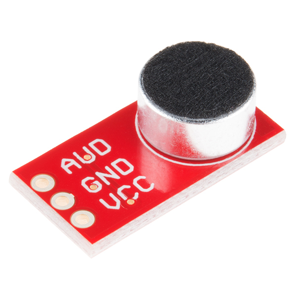
SparkFun Electret Microphone Breakout
BOB-12758 -
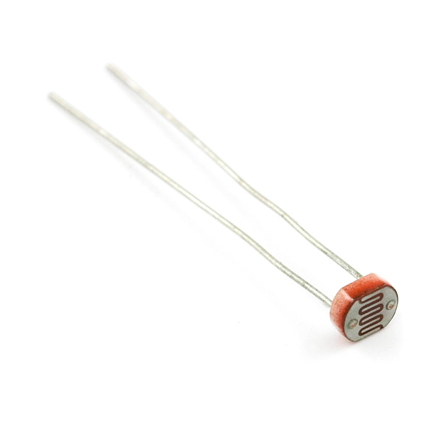
Mini Photocell
SEN-09088 -
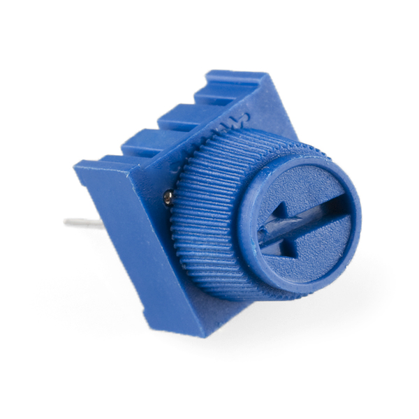
Trimpot 10K Ohm with Knob
COM-09806 -
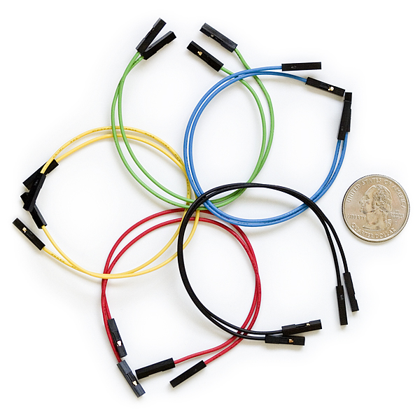
Jumper Wires Premium 6" Mixed Pack of 100
PRT-09194 -
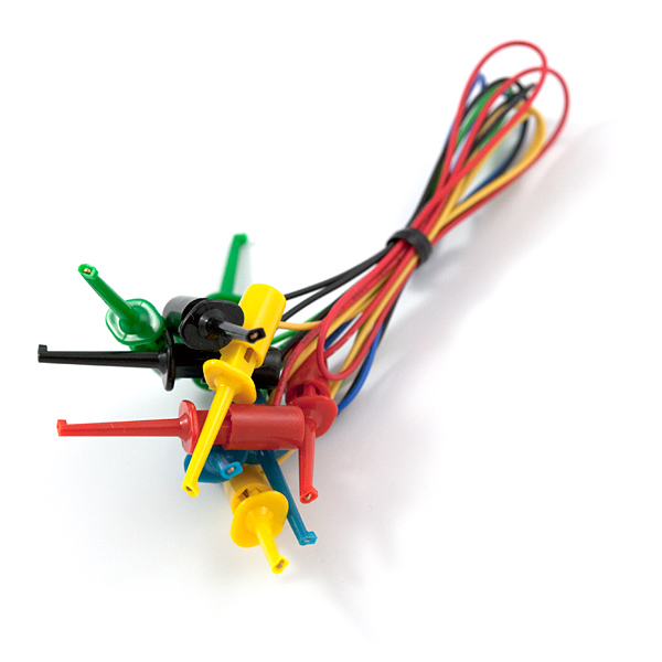
IC Hook Test Leads
CAB-00501
Below, are some basic example sketches for capturing analog data from generic devices such as a potentiometer or photocell.
Users can find this sketch in the File > Examples > 01.basics > AnalogReadSerial drop-down menu.
AnalogReadSerial.ino
Users can find this sketch in the File > Examples > 01.basics > ReadAnalogVoltage drop-down menu.
ReadAnalogVoltage.ino
Analog Output
AnalogWave Library
To implement the AnalogWave library from the Renesas Arduino core, users will need to link the library at the beginning of their sketch.
Once linked, users will need to create an instance of the analogWave class and declare a DAC pin for the output.
Tip
In the Renesas-Arduino core, DAC and DAC1 are predefined variables for their corresponding GPIO pins on the RA6M5 Thing Plus.
Below, are a few of the key methods available for the analogWave class:
Methods in analogWave.h
/* begin the output of the waweform the frequency is the one the complete
   set on sample are output (all samples will be output in 1 period */
bool begin(float freq_hz);
/* updated the frequency used */
bool freq(float freq_hz);
/* make the current index in the buffer to "jump" of the specified quantity */
void offset(uint32_t o);
/* start the generation of sample */
void start();
/* stop the genration of sample */
void stop();
/* every sample is multiplied for this factor must be a value between 0 and 1 */
void amplitude(float amplitude);


void sine(float freq_hz);
void square(float freq_hz);
void saw(float freq_hz);
For more information, please refer to the analogWave.cpp file in the AnalogWave library.
When generating an output signal from the DAC of the RA6M5 Thing Plus, users will need to define the waveform's type and frequency:
Oscilloscope
Oscilloscopes are the perfect tool to capture the waveform of a signal output. While useful, not all users will have access to this type of test equipment. For this example, user will need connect the probe from an oscilloscope to the DAC (A0) and GND GPIO pins.
Sine Wave
#include "analogWave.h" // Include the library for analog waveform generation

analogWave wave(DAC);   // Create an instance of the analogWave class, using the DAC pin

int freq = 60;  // in hertz, change accordingly

void setup() {
  wave.sine(freq);       // Generate a sine wave with the initial frequency
}

void loop() {}

A screen capture of a sine wave output from the DAC GPIO, which recorded on an oscilloscope.
Oscilloscope Adjustments
The DAC of the RA6M5, generates a waveform with a positive voltage. Therefore, user may need to adjust the vertical position of the probe's input channel.
Users may also find it helpful, to set the trigger on a discretized voltage step.
Feedback Loop
Another method to record the signal generated by the DAC, is with a jumper (wire) and looping a output signal from the DAC1 GPIO pin back into the A2 GPIO pin. While an oscilloscope is very useful, this is a more practical and cost-effective alternative for users. With this example, users are free to utilize any method or hardware they have to connect the DAC1 and A2 GPIO pins together. However, we recommend some IC hooks for a temporary connection.
Optional Hardware
-
IC Hook Test Leads
CAB-00501 -
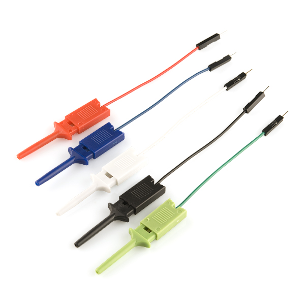
IC Hook with Pigtail
CAB-09741 -
Jumper Wires Premium 6" Mixed Pack of 100
PRT-09194 -
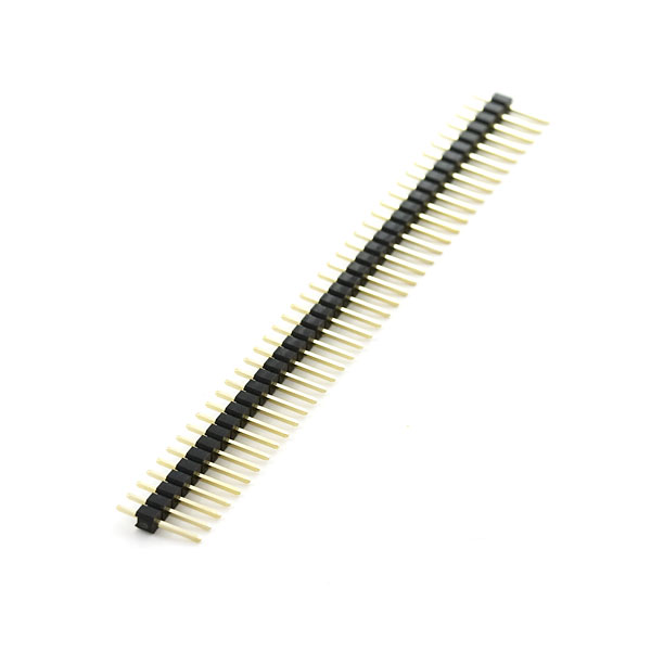
Break Away Headers - Straight
PRT-00116 -
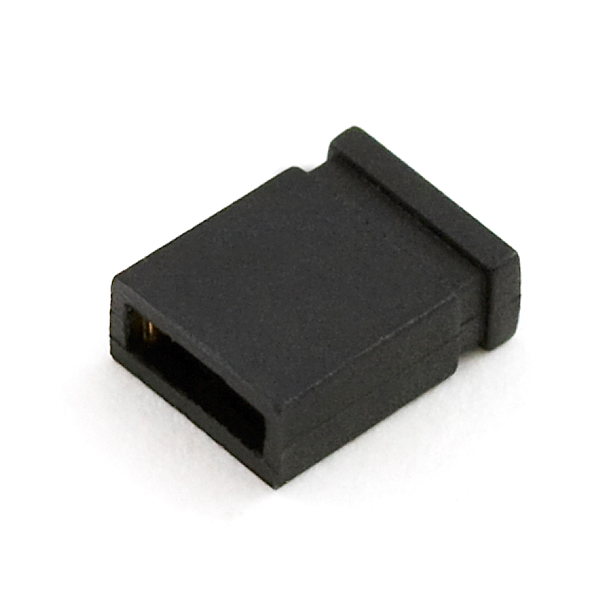
Jumper - 2 Pin
PRT-09044
After users have jumpered the GPIO pins and uploaded the example code, they will need to open the Serial Plotter in the Arduino IDE. Once opened, the tool will begin to plot the values that are received from the serial port. It should be noted that the Serial Plotter tool is unavailable in the legacy Arduino IDE v1.x.x; and some users may need to upgrade to the new Arduino IDE v2.x.x to access this tool. Additionally, the speed and buffer of the Serial Plotter tool are limiting factors in its performance. Therefore, careful consideration should be made when adjusting the waveform frequency and the delay intervals between readings.
Sine Wave
#include "analogWave.h" // Include the library for analog waveform generation

analogWave wave(DAC1);   // Create an instance of the analogWave class, using the DAC pin

int freq = 1;  // in hertz, change accordingly

void setup() {
  Serial.begin(115200);  // Initialize serial communication at a baud rate of 115200
  wave.sine(freq);       // Generate a sine wave with the initial frequency
}

void loop() {
  // Print the updated frequency to the serial monitor
  Serial.println(String(analogRead(A2)));
  delay(20);      // Delay for 20ms before repeating
}
Serial Plot

DAC GPIO, which was read by the A2 GPIO.
Other Waveforms
Users can modify this example to generate other types of waveforms, as shown in the examples below.

DAC GPIO, which was recorded by the A2 GPIO.
Square Wave
Users can modify the type of waveform output by the DAC. The modification below will generate a square waveform:
wave.sine(freq);
wave.square(freq);

DAC GPIO, which was recorded by the A2 GPIO.
Sawtooth Wave
Users can modify the type of waveform output by the DAC. The modification below will generate a sawtooth waveform:
wave.sine(freq);
wave.saw(freq);